1 CHAPTER 15. SPECIAL OVERLAY DISTRICTS TABLE OF CONTENTS ARTICLE 1. GENERAL............................................................................................................. 3 Sec. 15.1.1. Purpose. ............................................................................................................ 3 ARTICLE 2. DEFINITIONS ....................................................................................................... 4 Sec. 15.2.1. [Reserved]. ........................................................................................................ 4 Sec. 15.2.2. List of Definitions. .............................................................................................. 4 ARTICLE 3. GREATER AUBURNDALE JPA OVERLAY DISTRICT ........................................ 6 Sec. 15.3.1. Purpose and Intent. ........................................................................................... 6 Map 15.3-1. ............................................................................................................................ 7 Sec. 15.3.2. Administration and Enforcement. ...................................................................... 9 Sec. 15.3.2.1. Applicability and Effective Date................................................................... 9 Sec. 15.3.2.2. Compliance with Overlay District Standards. .............................................. 9 Sec. 15.3.2.3. Flexibility and Alternate Design Considerations. ......................................... 9 Sec. 15.3.2.4. Development Review and Approval Process. ........................................... 10 Sec. 15.3.2.5. Non-Compliance. ...................................................................................... 12 Sec. 15.3.2.6. Application Fees. ...................................................................................... 12 Sec. 15.3.2.7. Appeals. .................................................................................................... 12 Sec. 15.3.3. Development Guidelines. ................................................................................ 12 Sec. 15.3.4. Design Standards. ........................................................................................... 13 Sec. 15.3.4.1. Façade Articulation. .................................................................................. 14 Sec. 15.3.4.2. Architectural Treatments. .......................................................................... 15 Sec. 15.3.4.3. Connection, Cross-Access and Circulation. .............................................. 15 Sec. 15.3.4.4. Parking...................................................................................................... 16 Sec. 15.3.4.5. Signage..................................................................................................... 20 Sec. 15.3.4.6. Landscaping. ............................................................................................ 28 Sec. 15.3.4.7. Fences and Walls. .................................................................................... 31 Sec. 15.3.4.8. Lighting. .................................................................................................... 33 Sec. 15.3.4.9. Building Ornamentation. ........................................................................... 35 Sec. 15.3.4.10. Streetside Principles. .............................................................................. 37
Transcript
1
CHAPTER 15. SPECIAL OVERLAY DISTRICTS
TABLE OF CONTENTS
ARTICLE 1. GENERAL ............................................................................................................. 3
Sec. 15.1.1. Purpose. ............................................................................................................ 3
Sec. 15.3.2. Administration and Enforcement. ...................................................................... 9
Sec. 15.3.2.1. Applicability and Effective Date. .................................................................. 9
Sec. 15.3.2.2. Compliance with Overlay District Standards. .............................................. 9
Sec. 15.3.2.3. Flexibility and Alternate Design Considerations. ......................................... 9
Sec. 15.3.2.4. Development Review and Approval Process. ........................................... 10
Sec. 15.3.2.5. Non-Compliance. ...................................................................................... 12
Sec. 15.3.2.6. Application Fees. ...................................................................................... 12
Sec. 15.3.2.7. Appeals. .................................................................................................... 12
Sec. 15.3.3. Development Guidelines. ................................................................................ 12
Sec. 15.3.4. Design Standards. ........................................................................................... 13
Sec. 15.3.4.1. Façade Articulation. .................................................................................. 14
Sec. 15.3.4.2. Architectural Treatments. .......................................................................... 15
Sec. 15.3.4.3. Connection, Cross-Access and Circulation. .............................................. 15
Sec. 15.3.4.4. Parking...................................................................................................... 16
Sec. 15.3.4.5. Signage. .................................................................................................... 20
Sec. 15.3.4.6. Landscaping. ............................................................................................ 28
Sec. 15.3.4.7. Fences and Walls. .................................................................................... 31
Sec. 15.3.4.8. Lighting. .................................................................................................... 33
Sec. 15.3.4.9. Building Ornamentation. ........................................................................... 35
Sec. 15.3.4.10. Streetside Principles. .............................................................................. 37
2
Sec. 15.3.4.11. Utilities. ................................................................................................... 42
Sec. 15.3.4.12. Outdoor Storage. .................................................................................... 43
Sec. 15.3.4.13. Screening. ............................................................................................... 44
Sec. 15.3.4.14. Low Impact Development. ...................................................................... 46
Sec. 15.3.5. Big Box Retail Development. ........................................................................... 50
Sec. 15.3.5.1. Dimensional Standards. ............................................................................ 50
Sec. 15.3.5.2. Site Coverage. .......................................................................................... 50
Sec. 15.3.5.3. Design Standards. .................................................................................... 50
Sec. 15.3.6. Village Center Development. ........................................................................... 53
Sec. 15.3.6.1. Purpose and Intent. .................................................................................. 53
Sec. 15.3.6.2. Dimensional Standards. ............................................................................ 53
Sec. 15.3.6.3. Design Standards. .................................................................................... 54
Sec. 15.3.7. Activity Centers. .............................................................................................. 56
Sec. 15.3.7.1. Regional & Tourism Commercial Activity Centers. ................................... 56
Sec. 15.3.7.2. Commercial Activity Centers. .................................................................... 59
Sec. 15.3.7.3. Business Park Center ............................................................................... 61
Sec. 15.3.8. Corridors ......................................................................................................... 66
Sec. 15.3.8.1. Purpose and Intent. .................................................................................. 66
Sec. 15.3.8.2. Applicability. .............................................................................................. 66
Sec. 15.3.8.2. Corridor Landscaping Standards. ............................................................. 66
3
CHAPTER 15. SPECIAL OVERLAY DISTRICTS
ARTICLE 1. GENERAL
Sec. 15.1.1. Purpose. An Overlay District is a zoning tool that provides specific design standards for development in a designated area. An overlay district is used to either protect the pre‐existing character of an area or to create a character that would not otherwise be possible through the enforcement of the existing development standards of the current base zoning district. Overlay districts exist as an additional layer of regulation atop of an underlying base zoning district, providing development standards that are typically above and beyond those established in the underlying base zoning district. The boundaries of an overlay district may or may not coincide with the boundaries of an underlying base zoning district and in some cases may cover more than one underlying base zoning district. Sec. 15.1.2. Relationship to Underlying Base Zoning District Provisions. Regulations applicable to the underlying zone remain in full force and effect except where superseded herein. Where there is a provision not expressed in the underlying zone, or where a provision herein is in conflict with the underlying zone, the provision of the overlay district shall supersede and regulate the development. Where a regulation is more restrictive in other Articles of this Code, the more restrictive regulation shall apply. Sec. 15.1.3. Relationship to Green Swamp Area of Critical State Concern Provisions. All density and intensity regulations specific to areas located within the Green Swamp Area of Critical State Concern supersede any such regulations in this section. All enhanced design standards provided in the Overlay sections apply to areas within the Green Swamp Area of Critical State Concern as these design standards include enhanced landscaping and low impact design.
4
ARTICLE 2. DEFINITIONS
Sec. 15.2.1. [Reserved]. Sec. 15.2.2. List of Definitions. Architectural Rhythm: The repetitive use of a group of visual elements across a building façade, which establishes a recognizable and coherent pattern of movement along a surface such as window and column arrangements, openings, and the extension of roof or cornice lines. Architectural Treatments: Enhancements applied to a building façade through painting, horizontal and vertical banding, belt courses, decorative cornices, simulated or faux texturing, or other similar material applications to provide ornamentation and visual interest. Belt Course: A continuous row or layer of stone, tile, brick, or other similar material across a wall or building surface. Bollard: A thick post or other designated design feature typically constructed of iron, steel, or concrete which is used to protect pedestrians and buildings from vehicles. Bollards may be used in architectural and landscaping applications, while also serving security purposes. Bollard styles and design materials differ depending on the use and security purpose they serve. Building Envelope: The exterior dimensions of a building that comprise its visible form and mass, including its height, width, depth, and shape. Building Mass: The combined physical impact of the shape and bulk of a building, as demonstrated by its height, width and depth. Built Environment: Human‐made spaces in which people live, work, and recreate on a day‐to‐day basis; an environment encompassed by places and spaces which have been created or modified by people including buildings, parks, and infrastructure and transportation systems. Cornice: A decorative feature, found under the eaves of a roof, or projecting architectural moulding along the top of a building or a wall plane, the uppermost projecting section of an entablature. Cross‐Access Easement: Connections provided for both motor vehicles and pedestrians, which provide interconnected access between abutting lots to destinations such as businesses, eateries, offices, open spaces, trail systems, bus stops, entertainment venues, and other uses. Façade (building façade): Any side of a building facing a public right‐of‐way or pedestrian‐oriented space and finished accordingly. Façade Articulation: Physical changes in the depth of the surface of a building, demonstrated through, but not limited to, the application of recessed entranceways, attached columns, recessed or projected windows bays, and other forms of architectural expression.
5
Florida‐Friendly Landscape: A landscaping method which conserves water, protects the environment, is adaptable to local conditions and is drought tolerant. The principles of Florida‐friendly design include planning and design, appropriate choice of plants, soil analysis, efficient irrigation, practical use of turf, appropriate use of mulches, and proper maintenance. Form (Building Form): The shape and mass of a building. Building shapes can emphasize certain directional characteristics either horizontal, vertical, or square/box. Furnishing Zone: An area between the curb of a street and the base of building which provides a functional space and in some cases a safety barrier for pedestrians through the use of street trees, decorative bollards, pedestrian lighting, benches, trash cans, and other street furnishings. Kickplate: A decorative panel or skirting along the base of a building, used to create a visual separation between a building and a pedestrian walkway. Kickplates should be constructed of durable materials to withstand the vigor’s of pedestrian activity. Low Impact Development (LID): Design techniques used to maintain or replicate pre‐development hydrologic regimes by creating a functionally equivalent hydrologic landscape. LID encompasses a variety of stormwater management techniques, including bio‐swales, rain gardens, and pervious pavements. These techniques reduce the amount of effective impervious area in a watershed, lessening the watershed volumes and runoff rates. Overlay District: A district that is superimposed over one or more zoning districts or parts of districts and that imposes specified requirements in addition to those applicable in the underlying base zoning district. Parapet: A low, solid, protective wall or railing along the edge of a roof. Pedestrian‐oriented space: An area designed with an emphasis placed on the visual and functional needs of the pedestrian. Pedestrian Walkway: An outdoor improvement which is designed primarily for the transport of pedestrians and/or bicyclists. Screening: Treatments used to visually shield or separate undesirable elements of a site. Commonly used to obscure parking areas, utilities, dumpsters, and other similar elements on a site. Walkability: A measure of how friendly an area is to walking. Factors influencing walkability include, but are not limited to the presence or absence and quality of footpaths, sidewalks, or other pedestrian walkways, traffic and road conditions, land use patterns, building accessibility, and safety considerations. Walkability within the built environment may be characterized by the 10‐minute (0.25 mile) walk rule.
6
ARTICLE 3. GREATER AUBURNDALE JPA OVERLAY DISTRICT Sec. 15.3.1. Purpose and Intent. The purpose of the Greater Auburndale JPA Overlay District is to create an economically viable and visually appealing environment. The intent is to develop a well‐balanced community, with a strong sense of place that supports a mix of housing types and employment opportunities. The JPA Overlay District encompasses lands south of Interstate‐4 between SR 559 and the Polk Parkway (Toll 570) south to Old Dixie Highway. The general boundary is shown on Map 15.3‐1. The Development Guidelines and Design Standards provided in this Article will provide design professionals, property owners, developers, planners, city staff and Elected Officials with a clear, common and predictable understanding of the site development and architectural design expectations of the JPA Overlay District. In addition, the City has prepared a “Design Development Concepts” document which is available for reference in Chapter 8 of the City’s Administration and Procedures manual. The purpose of the document is to provide additional understanding of the City’s development vision of the JPA Overlay District.
7
Map 15.3‐1.
JPA Boundary – General Overlay Area
8
9
Sec. 15.3.2. Administration and Enforcement.
Sec. 15.3.2.1. Applicability and Effective Date.
Commencing the date of the adoption of the JPA Overlay District (May 2, 2016), the JPA Overlay District provisions shall apply to the development of all land therein whether publicly or privately held. No development shall be undertaken without prior authorization pursuant to the JPA Overlay District. Any building, structure, or parking area that lawfully exists at the time the JPA Overlay District is enacted, which would not otherwise be permitted under the JPA Overlay District, may be continued in the same manner as it existed before the effective date of the JPA Overlay District. Any future construction, additions, reconstruction, or renovation shall be subject to the requirements of the JPA Overlay District.
The JPA Overlay District standards apply to the following:
• All new construction of buildings or structures. • All exterior building improvements requiring a building permit. • All new or reconstructed parking areas with five or more spaces.
Sec. 15.3.2.2. Compliance with Overlay District Standards.
At the time of application for any site development plan and/or building permit, the applicant shall demonstrate that the proposed building, structure, improvement, or renovation complies with the requirements of the JPA Overlay District. No building permit shall be issued until the requirements of the JPA Overlay District have been met. It is the applicant’s responsibility to provide the necessary information to City staff to determine compliance with this section.
The Administrative Official, or his or her designee, shall apply the development guidelines and design standards to all development activity within the JPA Overlay District. Flexibility in development proposals may be provided so long as the proposed improvements meet the purpose and intent of the JPA Overlay District.
Sec. 15.3.2.3. Flexibility and Alternate Design Considerations.
The City recognizes that specific sites and uses may exhibit unique needs and requirements. The City will work with applicants to provide flexibility through alternate design considerations so long as the proposed improvements meet the purpose and intent of JPA Overlay District.
Sec. 15.3.2.3.1. Alternative Design Criteria. Alternative design(s) may be considered and approved if any of the following criteria are evidenced:
A. Does the proposal meet the intent and the general direction set forth by what is required in
this Article?
B. Is the specific change superior in design quality to that potentially achieved by what is required in this Article?
10
C. Is the proposed alternative an application that is necessary to better respond to constraints
of the site, the use, or its surroundings?
D. Is the proposed alternative part of an overall, thoughtful and comprehensive approach to the design of the project as a whole or to the vision of the adopted JPA Overlay District?
Sec. 15.3.2.3.2. Approval of Alternative Design.
A. The Administrative Official, or his or her designee, shall review and approve alternate deign
requests.
B. The Administrative Official, at his or her discretion, may forward any alternate design request to the Planning Commission and/or City Commission for consideration and approval.
Sec. 15.3.2.4. Development Review and Approval Process.
To ensure that development, redevelopment, and improvements are consistent with the purpose and intent of the JPA Overlay District, the following review process will be followed prior to site development plan approval or the issuance of building permits:
Sec. 15.3.2.4.1. Application Process.
A. Pre‐Application Meeting.
Unless otherwise waived, at the discretion of the Administrative Official, or his or her designee, a pre‐application meeting shall be held for each new development plan submitted to the City for review. The intent of this meeting is to discuss early and informally the purpose and effect of the JPA Overlay District and the guidelines and standards contained herein. It is recommended that the applicant provide a site analysis plan at the pre‐application meeting for discussion. The purpose of the site analysis plan is to ensure that important elements of the development proposal have been adequately identified prior to the creation of a full‐scale site development plan. The site analysis plan, which may be developed as a sketch, shall include, at a minimum, the following features: 1. Property boundaries. 2. Representation of adjacent lots, existing buildings, adjacent streets, and opportunities
for connectivity. 3. Location of proposed uses and buildings on the lot.
11
B. Application Submittal.
The applicant shall submit an application, including site development plans and other project specific attachments for development review. The application package shall be prepared in accordance with all site plan review information requirements established in the City’s Administration and Procedures Manual. All materials shall be submitted to the Administrative Official, or his or her designee, for processing and review. The following items as determined by the Administrative Official, or his or her designee, must be submitted with the application:
1. Site plan meeting the requirements of Chapter 5, Sec. 5.1.3 of the City’s Administration
and Procedures Manual.
2. Statement of how the development proposal meets the requirements of the JPA Overlay District.
3. Proposed design alternative(s), if any, with a statement as to why the provisions of Sec.
15.3.4 are unable to be met and how the alternative(s) meets the purpose and intent of the JPA Overlay District.
4. Requested incentives, if any.
5. Any applicable studies (i.e., traffic analysis) required for development approval.
Sec. 15.3.2.4.2. Approval Process.
A. Following receipt of an application, the City shall review the development request in relation
to the Comprehensive Plan, zoning and other applicable land development regulations, and shall identify matters of development policy concern to which the applicant shall address particular attention.
B. Upon completion of the review, the Administrative Official, or his or her designee, shall provide written comments to the applicant detailing any issues identified during the review. The applicant shall respond to the comments at this stage of the review and shall submit any revised application and applicable exhibits to the Administrative Official, or his or her designee.
C. When the Administrative Official, or his or her designee, determines that all comments have
been adequately addressed and the requirements of all applicable City, state and federal regulations have been met, the Administrative Official, or his or her designee may approve, approve with changes, or deny the site development plan, based on the written comments and recommendations; or if Planning Commission or City Commission action is required, the Administrative Official, or his or her designee, shall place the request on the next scheduled meeting agenda of the appropriate hearing body.
D. At the Administrative Official’s discretion, any development that may have compatibility
concerns may be sent to the Planning Commission and/or City Commission for consideration and approval.
12
E. Following approval of the site development plan, the applicant may proceed to submit
construction drawings. Construction drawings shall be submitted to the Administrative Official, or his or her designee, for processing and additional review, as necessary, prior to the Building Official’s review and issuance of any building permits. Drawings shall include, but are not limited to, building plans, drainage and stormwater management facilities, road and driveway construction specifications, landscaping and lighting plans, and all design applications required under the provisions of the JPA Overlay District.
Sec. 15.3.2.5. Non‐Compliance.
Failure to comply with an approved site plan or any of the conditions upon which such approval was contingent, including time limits for performance, shall be cause to deny issuance of a building permit or, where a permit has been issued pursuant to an approved site plan, to render such building permit invalid. Any action, construction, development or use of property undertaken in violation of the provisions of this Code shall constitute a violation of this Code and may be subject to a stop‐work order. Sec. 15.3.2.6. Application Fees.
Application fees associated with plan review and approval of development or redevelopment projects in the JPA Overlay District shall be set by the City Commission.
Sec. 15.3.2.7. Appeals.
Decisions and approvals made by the Administrative Official, or his or her designee, may be appealed to the City Commission.
Sec. 15.3.3. Development Guidelines. The development and functionality of buildings and spaces within the JPA Overlay District shall adhere to the following development guidelines.
A. Site design shall be organized to respect the arrangement of buildings, open space, accessibility,
and landscape elements on adjacent lots. B. Buildings and open spaces shall be designed to provide mutual benefits of natural light,
accessibility, circulation, and views. C. A single, large, dominant building mass shall be avoided. Changes in mass shall be related to
entrances, the integral structure and the organization of interior spaces and activities, and not merely for cosmetic effect.
D. Multi‐story buildings shall be designed to minimize overall building massing. This can be
accomplished through upper story setbacks, façade articulations, and other architectural treatment methods.
13
E. Flexibility in building orientation shall be provided to promote an interesting visual environment. A building’s orientation may vary depending on site constraints and the need to meet other design standards and/or regulations.
F. Building orientation with a primary operable entrance on the street‐side of a lot is encouraged to
help create an active street frontage. G. Site and building design shall support a mix of transportation options, including walking, bicycling,
driving and other transit modes. The planned‐use of land shall support walkability where practical and feasible.
H. Building designs should be responsive to climate patterns of the Central Florida region in order to
minimize unnecessary heat gain from sun exposure and provide protection for pedestrians from inclement weather conditions.
I. Buildings within the same development envelope (i.e., on the same lot or parcel) are encouraged
to utilize similar architectural treatments consistent with other buildings on the same lot.
Sec. 15.3.4. Design Standards.
The following design standards are applicable to all development within the JPA Overlay District unless specifically stated otherwise. These standards are intended to enhance the safety, wellbeing, accessibility, interconnectedness, economic viability and aesthetic quality of the JPA Overlay District. To help understand some of the general design terms and strategies provided in this section, please refer to Figure 15.3‐1 below.
Figure 15.3‐1.
Architectural Terms
14
Sec. 15.3.4.1. Façade Articulation.
Façade articulation applies primarily to the street‐side and/or pedestrian oriented side of a building. The following shall be required for all buildings or structures located on the development site, except as expressly supplemented or modified for specific activity centers located within the JPA Overlay District.
A. Blank, opaque wall areas shall not exceed ten feet (10’) in vertical direction or twenty feet (20’)
in the horizontal direction of any primary façade. B. The first floor shall be designed so that 45 percent of the total surface area of each first floor
frontage is comprised of transparent windows, doors, and other openings to provide visual interest and compliment pedestrian activity at the ground level, unless regulations for specific activity centers specify otherwise.
C. Buildings with a primary operable entrance on the street‐side of a building shall provide a
recessed or projected entranceway. For corner lots, the primary operable entrance may be located at the corner.
D. Buildings whose primary operable entrance is not located on the street‐side of the building shall
provide a minimum of 30 percent transparency thru the use of windows and/or other openings along the total surface area of each street‐side building surface to provide visual interest and security, unless regulations for specific activity centers specify otherwise.
E. Buildings designed for multiple tenant spaces at the ground level, particularly, retail storefronts,
shall provide visible articulations between such spaces and include well‐defined entranceways. F. Upper stories shall provide transparent windows, doors, or other openings along 30 percent of
the total surface area of each upper floor façade, unless regulations for specific activity centers specify otherwise.
G. Simulated or opaque windows may be used to provide visual interest, but shall not constitute
the fulfillment of meeting any required minimum transparency or other opening requirements. H. Clearly identifiable separation lines between the first floor and upper floors shall be expressed
through the use of decorative cornice lines or other architectural treatments. Such lines should be coordinated with buildings on adjacent lots to provide visual linkages. Separation lines shall have a minimum vertical dimension of 12 inches, projected outward from the wall 2 inches.
I. Varying roof heights and wall planes are encouraged to provide additional visual interest.
Architectural rhythm should also be considered in the design of roof heights and wall planes, and should be coordinated with those of existing buildings on adjacent lots.
J. A kickplate, when applied, shall create a visual transition between the base of the building and
pedestrian walkways. Kickplates shall be coordinated with adjacent buildings to provide visual linkages. Kickplates shall have a minimum vertical dimension of 12 inches and be projected outward from wall 2 inches.
15
Sec. 15.3.4.2. Architectural Treatments.
Architectural treatments enhance the attractiveness of buildings and structures. Such treatments shall be applied in a consistent manner along all sides of a building façade. Architectural treatments include: A. Horizontal banding or belt courses, when applied shall have a minimum vertical dimension of 12
inches and be projected outward from wall 2 inches. B. Architectural moulding, when applied may be decorative framing around windows and doors,
decorative caps on columns, or other types of architectural expression on wall surfaces. C. Decorative cornices, when applied shall have a minimum vertical dimension of 12 inches and be
projected outward from wall 2 inches. D. Application of primary and secondary surface materials. The use of multiple surface materials is
encouraged to add architectural interest.
1. Suggested Surface Materials. • Stucco or synthetic stucco. • Brick or glazed brick. • Tinted and textured concrete masonry. • Concrete (Pre‐Cast or Cast‐in‐place). • Split face concrete block. • Wood or simulated wood finishes. • Fiber Cement (Hardiplank®). • Stone, cast stone, marble, or similar material. • Glass and glass storefront. • Painting surfaces.
2. Prohibited Surface Materials.
• Metal and steel panels or metal sheathing, with the exception that such material may be used if finished with an approved surface material (see Suggested Surface Materials).
• Exposed concrete block. • Exposed plywood or particle board.
Sec. 15.3.4.3. Connection, Cross‐Access and Circulation.
In order to create safe, quality built environments, it’s important to establish good circulation of movement and cross‐access among spaces and places. Linkages for both pedestrians and motor vehicles shall be considered in all development proposals.
Sec. 15.3.4.3.1. Pedestrian Access.
A. Construction of sidewalks shall be required for all new development and redevelopment
activities within the JPA Overlay District. Sidewalks shall have a minimum width of five feet (5’) and shall be constructed along all frontage roadways.
16
B. Direct ADA‐compliant pedestrian access shall be provided from public sidewalks to the
primary operable entrance of a business or residence. Such access shall be facilitated by sidewalks and/or clearly delineated crosswalks through vehicular parking areas and shall be constructed at a minimum width of five feet (5’).
C. Site designs shall include pathways which allow for pedestrian and bicycle connectivity
within activity centers and provide connection to surrounding residential areas. D. Development on property adjacent to the Auburndale TECO Trail shall provide direct
pedestrian/bicycle access to the Trail. Where a direct connection cannot be provided, access shall be established, connecting the development site with a public sidewalk or other multi‐use path which connects to the Trail.
E. Cross‐access connectivity shall be established between adjacent non‐residential lots. Where
a neighboring lot is undeveloped, location(s) for future connection shall be established. F. Pedestrian pathways shall be constructed of a paved or other approved hard surface
material meeting accessibility standards. G. All crosswalks, direct‐access, and cross‐access pedestrian walkways within vehicular parking
areas shall be constructed of a different surface material than that of the general parking area and driveways. The materials used shall clearly delineate such access‐ways from the surrounding parking and driveway surface areas.
Sec. 15.3.4.3.2. Vehicular Access.
A. Driveway stub‐outs shall be considered in all site designs as a means to provide future
interconnectivity with adjacent properties. B. Driveways serving as a shared access point along abutting property lines may be utilized to
reduce the number of driveway cuts. Shared access shall be established through an access easement agreement. All access/easement agreements shall be recorded with the Polk County Clerk of Courts prior to issuance of any building permits.
Sec. 15.3.4.4. Parking.
Design standards for parking areas shall respect parking standards established in Chapter 11 and any landscaping standards in Chapter 10 of the City’s Land Development Code, except as expressly supplemented or modified in this section.
A. Parking areas for motor vehicles is encouraged to be located on the sides and rear of buildings,
in order to shield and minimize the overall appearance of parking areas and to promote a safe and inviting pedestrian environment.
B. Parking areas for corner lots shall be located toward the interior corner of the lot, as best as
feasibly possible. Site constraints may be considered in the design of parking areas on corner lots.
17
C. Off‐street parking areas shall include internal landscape islands to help visually soften the
impact of paved surfaces. Curbing shall be installed at the edges of all landscape islands within parking areas.
D. Structured Parking Garages:
1. Where structured parking garages are used, the architectural style of the parking garage
shall become a part of the architectural style of the surrounding buildings, respecting the language of design, materials and details of the surrounding architecture.
2. The first floor of a parking garage may include retail, office, personal service and professional uses. Such use of the first floor is highly encouraged to maintain the pedestrian integrity of the street, especially where high volumes of pedestrian activity may be experienced.
E. Low Impact Development standards are encouraged to be used within parking areas in
accordance with Sec. 15.3.4.14.
Sec. 15.3.4.4.1. On‐Street Parking.
A. On‐street public parking may be provided where adequate right‐of‐way exists. The construction of on‐street parking spaces, directly and wholly abutting the lot, may be provided and counted towards the off‐street parking requirement of the development site it is intended to serve, provided that:
1. The adjacent right‐of‐way has not been previously utilized for parking or, in cases where
the adjacent right‐of‐way has been used for parking only those spaces in addition to the number of existing spaces shall be counted;
2. Such parking spaces are clearly identified on the final site development plan and designed in accordance with appropriate City, County and/or State standards, as applicable; and
3. Such parking spaces shall be publicly accessible and cannot be reserved or restricted by
the owner(s) or tenant(s) of the lot, unless approved by the City Commission for special events or valet parking purposes.
B. One parking space credit shall be given for each on‐street public space constructed.
C. No part of an on‐street parking space shall extend past a side property line of the lot it
serves.
D. In the event the City, County or State removes the parking spaces at any time for a public purpose, the property shall be considered lawfully nonconforming with respect to parking.
18
Sec. 15.3.4.4.2. Shared Off‐Street Parking.
Notwithstanding any other parking requirements set forth in this Section, shared use of parking facilities may be approved when two (2) or more distinguishable uses are established on a single site or multiple neighboring sites. The minimum number of parking spaces required to serve the combination of all uses shall be determined in the following manner: Multiply the minimum required parking for each individual use (as set forth under the appropriate zoning district within the Minimum Off‐street Parking requirements in Chapter 5 for each use) by the appropriate percentage (as set forth in Table 15.3‐1, Shared Use Parking Credit Schedule) for each of the six (6) designated time periods and then add the resulting sums from each vertical column. Where the computation results in a fractional number, a fraction over one‐half (1/2) shall require one space. The column total having the highest total value is the minimum shared parking space requirement for that combination of land uses.
Institutional (non‐place of worship) 100% 20% 5% 10% 10% 5% Institutional (place of worship) 10% 5% 5% 100% 50% 5% Source: TDM Principles for Shared Parking, Victoria Transport Policy Institute.
Sec. 15.3.4.4.3. Short‐term Bicycle Parking.
A. One (1) bicycle parking space shall be provided for every 10 automobile parking spaces, or fraction thereof required for the use, unless otherwise specified within individual activity centers.
B. Racks or other facilities for bicycle parking shall be established as follows. Examples of several types of standard bicycle racks are provided in Figure 15.3‐2.
1. Designed to allow the frame and wheels of each bicycle to be secured and protected
against theft; 2. Designed to avoid damage to the bicycles;
19
3. Anchored to resist removal and solidly constructed to resist damage by corrosion and vandalism;
4. Located to prevent damage to bicycles by cars; and 5. Located so as not to interfere with pedestrian movements.
Figure 15.3‐2.
Bicycle Rack Examples
Sec. 15.3.4.4.4. Long‐term Bicycle Parking.
A. General. Long‐term bicycle parking provides employees, residents, commuters, and others who generally stay at a site for several hours, a secure and weather‐protected place to park bicycles. Long‐term bicycle parking is not required, but is highly encouraged. Racks used for bicycle parking shall meet the design standards as established for short‐term bicycle parking. Examples of several types of long‐term bicycle parking facilities are provided in Figure 15.3‐3.
B. Design Standards.
1. Long‐term bicycle parking must be located on site or within 300 feet of the site as measured along the nearest pedestrian walkway.
2. Areas devoted to long‐term bicycle parking shall be paved of a hard surface material. 3. Long‐term bicycle parking shall be provided in racks or in lockers. 4. Where lockers are provided, lockers shall be securely anchored and installed per the
manufacture’s design standards. 5. At least 50 percent of required long‐term bicycle parking must be covered and meet the
following standards:
20
a. Provided inside buildings, under roof overhangs, awnings, or canopies, within
bicycle lockers, or within or under other structures approved by the Administrative Official, or his or her designee.
b. For covered spaces not located in a building or within a locker, the cover shall be:
1. Constructed as a permanent structure, not to include carports or prefabricated
metal structures. 2. Designed to protect the bicycle from rainfall. 3. Constructed at a height of at least 7‐feet above the finish grade of the paved
surface.
Figure 15.3‐3.
Long‐Term Bicycle Parking Facilities
Sec. 15.3.4.5. Signage.
Signage requirements for all development shall respect the regulations in Chapter 5 and Chapter 7 of this Code, except as expressly supplemented or modified under the regulations established for the JPA Overlay District. Signage design shall be consistent with the design, character, and materials and finishes used on the building(s) for which a sign is representing.
Sec. 15.3.4.5.1. Computation of Signage Size.
The area of a sign is considered the entire area within the smallest circle, triangle, parallelogram, or other geometric shape that encloses the extreme limits of any writing, picture, logo, representation, emblem, or figure of similar character, together with any frame or other material or color forming an integral part of the display or used to differentiate such sign from the background against which it is placed, excluding the necessary supports or uprights on which such sign is placed. Figure 15.3‐4 provides an illustration of the regulated signage area.
21
Sec. 15.3.4.5.2. Permitted Signs. The following signs are permitted within the JPA Overlay District:
• Monument • Surface‐mounted, including affixed and projecting • Under canopy • Directional • Directory
Sec. 15.3.4.5.3. Prohibited Signs. The following exterior signs are prohibited within the JPA Overlay District:
• Pole signs; • Internally illuminated signs; • Temporary signs (banners, balloons, trailer signs, etc.), with the exception of real estate or
special event signs as may be allowed pursuant to Temporary Signs in Chapter 7 of this Code;
• Neon signs; • Internal or backlit awnings or any signage placed on an awning; • Any type of sign, temporary or permanent, which has moving parts or appears to have
movement; • Temporary or permanent signage on fencing; • Roof signs; • Signs for individual businesses, including advertisements that are attached to benches, light
and power poles, trash receptacles and other street furnishings.
Sec. 15.3.4.5.4. Design Standards for Monument Signs.
A. The structural element of a monument sign shall not exceed ten feet (10’) in height as measured from natural grade, unless specified otherwise. See Figure 15.3‐4 for dimensional standards of monument signs.
B. Each development is permitted one (1) monument sign per roadway frontage. No more
than two (2) monument signs shall be permitted for any single development site, unless specified otherwise.
C. The total sign area may be up two (2) square feet for each lineal foot of building frontage or
one (1) square foot for each lineal foot of lot street frontage whichever results in a larger sign area, but not to exceed a total of 96 square feet, where the signage area does not exceed forty‐eight (48) square feet on a single side.
D. Monument signs may also contain an area designated as a reader sign board, not to exceed fifty percent (50%) of the signage surface area per side.
22
E. All monument signs shall be set back ten (10) feet from any property line and shall not materially impede visibility at street intersections or at intersections of driveways with streets.
F. Monument signs shall be consistent with the design, character, and materials and finishes
used on the building(s) for which it serves. Figure 15.3‐5 provides examples of monument signage.
Figure 15.3‐4.
Dimensional Standards for Monument Signs
Figure 15.3‐5.
Examples of Monument Signage
23
Sec. 15.3.4.5.5. Design Standards for Affixed Signs.
A. Affixed signs for buildings with a single business or occupant.
1. Size Permitted: One (1) square foot for each linear foot of the building width that faces the street frontage, provided that the total signage area shall not exceed two hundred (200) square feet, including buildings on corner lots. (For example, if the width of the building facing the front of the lot is fifty (50) feet wide, the maximum total signage area is fifty (50) square feet. If the building is on a corner lot, then the widths of the building facing multiple street frontages can be added together to determine the total signage area but in no case shall the total building signage exceed two hundred (200) square feet, nor shall any individual sign exceed the square footage corresponding to the linear width of the building side on which that sign is posted.)
2. Number of Building Signs Permitted: Not more than two (2) building signs shall be
allowed on any building.
B. Affixed signs for buildings with multiple businesses or occupants.
1. Size Permitted: One (1) square foot for each linear foot of the unit(s) occupied by one (1) business or occupant, provided that the total signage area shall not exceed two hundred (200) square feet for any one (1) business. If the business or occupant is on the comer then the widths of the business or occupant facing multiple street frontages can be added together to determine the total signage area but in no case shall the total business or occupant signage exceed two hundred (200) square feet, nor shall any individual sign exceed the square footage corresponding to the linear width of the building side on which that sign is posted. (For example, if the width of a unit or several units, occupied by one (1) business is sixty‐five (65) feet, then one (1) sign, a maximum of sixty‐five (65) square feet of signage area is permitted.)
2. Required Spacing between Signs on Buildings with Multiple Occupants: Building signs
for different occupants shall be separated by a minimum distance of thirty‐six (36) inches.
Sec. 15.3.4.5.6. Design Standards for Projecting Signs.
Projecting signs shall be permitted as wall‐mounted signs. See Figure 15.3‐6 for an example of a Projecting Sign. Projecting signs are subject to the following standards: A. Projecting signs shall be included in calculating the maximum allowable building signage and
shall have no more than two sides. B. One (1) projecting sign may be permitted per principal ground‐floor business. C. Projecting signs shall not exceed eight (8) square feet in sign area if mounted at a height of
fifteen (15) feet or lower as measured from the finished sidewalk to the bottom of the sign.
24
D. Projecting signs shall not exceed twenty‐five (25) square feet in sign area if mounted higher
than fifteen (15) feet as measured from the finished sidewalk to the bottom of the sign. E. Projecting signs shall be located within five feet (5) (horizontally) of the principal business
entrance. In no case, however, shall a projecting sign be mounted within ten (10) feet of any other projecting sign.
F. Projecting signs may project no more than forty‐two (42) inches from the building wall. G. Projecting signs shall maintain a seven (7) foot clearance, between the bottom of the sign
and the finished surface of all public and private pedestrian pathways.
Figure 15.3‐6. Projecting Sign
Sec. 15.3.4.5.7. Design Standards for Under Canopy Signs.
Signs mounted under a canopy, awning, or awning‐like structure shall be a maximum of four (4) square feet in size, shall maintain a clearance of seven (7) feet from the bottom of the sign to the top of the walkway beneath, and shall swing freely. Under canopy or under awning signs that are not visible from the property frontage shall not count against the total signage. See Figure 15.3‐7 for an example of an Under Canopy Sign.
Figure 15.3‐7.
Under Canopy Sign
25
Sec. 15.3.4.5.8. Residential Subdivision Entryway Signs.
A residential entry sign is a sign placed at the entrance of an apartment complex or single‐family subdivision in order to identify the name of a particular development. Figure 15.3‐8 provides examples of residential entryway signage types. The following standards apply to all residential subdivision signs within the JPA Overlay District.
A. Residential Subdivision Entryway Signs shall be considered monument signs for
purposes of calculating size and location requirements and shall meet the general regulations for monument signs as provided in Sec. 15.3.4.5.4, except as expressly supplemented or modified in this section.
B. The maximum number of signs permitted for each residential subdivision entrance shall be two (2) signs.
C. The maximum number of signs permitted on each side of a residential subdivision
entrance shall be one (1) sign. D. A single, monument sign, located within a median, as part of a boulevard entrance,
may be used in‐lieu of two (2) signs established on either side of a subdivision entrance. E. The signage area of a single entry sign, located on either side of a subdivision
entrance, shall not exceed forty‐eight (48) square feet. F. A monument sign located within a median, as part of a boulevard entrance, may
have a signage area of up to a total of 48 square feet, where the signage area does not exceed twenty‐four (24) square feet on a single side.
G. The maximum height of the structure serving a single entry sign, located on either
side of a subdivision entrance, shall not exceed ten feet (10’) as measured from natural grade.
H. The maximum height of the structure serving a single entry sign located within a
median, as part of a boulevard entrance, shall not exceed five feet (5’) as measured from natural grade.
I. Residential Entryway Signs shall be architecturally compatible with the design and
Sec. 15.3.4.5.9. Non‐residential, Multi‐Occupant Complex Signs.
The following standards shall apply for developments of two (2) or more non‐residential uses that are under common land ownership or that share common property frontage. Figure 15.3‐9 provides examples of non‐residential, multi‐occupant complex signage types.
A. Non‐residential, multi‐occupant complex signs shall be considered monument signs
for purposes of calculating size and location requirements and shall meet the general regulations for monument signs as provided in Sec. 15.3.4.5.4, except as expressly supplemented or modified in this section.
B. Lots or parcels having frontage on an arterial or collector roadway shall be allowed one
(1) sign with a signage area not to exceed a total of 300 square feet, where the signage area does not exceed 150 square feet on a single side, for every seventy‐five feet (75’) to two hundred fifty feet (250’) of street frontage. For lots or parcels having two hundred fifty (250) feet or more of frontage, an additional sign shall be allowed along the frontage roadway, limited to the same size requirements contained herein. The maximum height of the structure serving the sign shall not exceed twenty feet (20’).
C. Lots or parcels having frontage on a local roadway shall be allowed one (1) sign with a
signage area not to exceed a total of 200 square feet, where the signage area does not exceed 100 square feet on a single side, for every seventy‐five feet (75’) to two hundred fifty feet (250’) of street frontage. For lots or parcels having two hundred fifty (250) feet or more of frontage, an additional sign shall be allowed along the frontage roadway, limited to the same size requirements contained herein. The maximum height of the structure serving the sign shall not exceed fifteen feet (15’).
D. For lots or parcels situated at intersections, an additional sign may be placed on the
secondary street frontage. The sign area and size shall comply with the frontage requirements, for specified roadway classifications, as provided in subsections B. and C. above.
E. No more than four (4) signs may be permitted for any single development site. F. Signs may be located within a median, as part of a boulevard entrance. G. Multi‐occupant Complex Signs shall be architecturally compatible with the design and
character of buildings and structures for which they serve.
27
Figure 15.3‐9.
Non‐Residential, Multi‐Occupant Complex Signs.
Sec. 15.3.4.5.10. Directory Signs.
Directory signs are permitted within residential subdivisions and non‐residential, multi‐occupant development sites. Directory signs shall respect the general regulations for monument signs as provided in Sec. 15.3.4.5.4, except as expressly supplemented or modified in this section. The following standards shall apply.
A. One (1) directory sign is permitted for each approved access driveway on a development
site. B. The maximum signage area for a directory sign is 25 square feet C. Directory signs shall be set back a minimum of thirty feet (30’) from a public right‐of‐way. D. Directory signs shall be set back a minimum of five feet (5’) from internal travel lanes and
shall not materially impede visibility at any street intersections or at intersections of driveways with internal travel lanes.
Sec. 15.3.4.5.11. Directional Signs.
Directional signs are permitted in accordance with the requirements for directional signage in Article 7 of this Code.
Sec. 15.3.4.5.12. Signage Lighting and Landscaping Requirements.
A. Sign Illumination. If exterior signs are lit they shall be lit by external light sources only. Lights
shall be installed, mounted, shielded and pointed toward the sign face so that spill‐over, glare, and light trespass on adjacent rights‐of‐way, properties, or skyward are completely avoided.
B. Wall‐mounted signs shall be lit with indirect light sources which light the subject sign while
at the same time emphasizing the continuity of the building surface. With indirect lighting, signage becomes an integral part of the building façade.
28
C. Lighting used to illuminate ground‐mounted or monument signs may utilize ground‐
mounted up‐lighting in accordance with the sign illumination standards established in subsection A. above.
D. Internal illumination may be acceptable when only the letters themselves – not the
background of a sign – are illuminated. E. The average illumination on the surface of a sign shall not exceed 3.0 footcandles. F. Sign Landscaping. All monument signs shall include a minimum thirty‐six inch (36”) wide
landscape strip surrounding the base of the monument sign. The landscape strip shall be planted with materials that attain a maximum height of thirty inches (30”) above the finished grade.
G. See Sec. 15.3.4.8.1. for building and landscape lighting standards.
Sec. 15.3.4.5.13. Signage Plan Requirements.
A signage plan is required as part the site development plan approval process for any development within the JPA Overlay District requiring site plan approval. The signage plan may be submitted as part of the site development plan or as a separate plan. The signage plan shall, at a minimum, provide the following:
A. Representation of how the signage will be consistent with the identity of the JPA Overlay
District. B. Representation of how the signage detailing, materials, coloring and lettering will be
consistent with the design and character of the principal structure for which the sign will represent.
C. Exhibits that display the size, type and materials proposed, including but not limited to,
building address identification, any required landscaping and method of illumination.
Sec. 15.3.4.6. Landscaping.
Landscaping requirements for all development shall respect the landscaping standards of Chapter 10 of this Code, except as expressly supplemented or modified under the regulations established for the JPA Overlay District. A. Landscape buffers are not required between uses within activity centers, except where a non‐
residential use directly abuts a residential use. B. Where landscape buffers are required and references to the types of buffers required are
specified (i.e., Type‐C), see the general landscape buffering standards provided in Sec. 15.3.4.6.1.
29
Sec. 15.3.4.6.1. General Landscape Buffering Standards.
A buffer yard is an area containing plant material, fences, walls and/or berms which provide a visual screen and physical separation between incompatible land uses. Buffer yards are intended as landscaped open space therefore, they shall be free of pavement and permanent structures other than fences, walls, berms, pedestrian paths, stormwater management and retention facilities, and signs.
Figure 15.3‐10 illustrates the planting requirements for buffer yards within the JPA Overlay District. Each buffer yard type provides the number and type of plantings required per each 100 linear feet, or fraction thereof, excluding any driveway access. The plant material does not need to be equally spaced and may be placed in any configuration, or grouped to best display the plant material within the required buffer yard area. When natural plant material is present, it may be counted towards the total buffer yard requirement for trees and shrubs provided the existing material is generally consistent with the intent of this Article.
30
Figure 15.3‐10.
Landscape Buffers
31
Sec. 15.3.4.6.2. Installation, Irrigation, Inspection and Maintenance.
A. Installation.
1. All plants shall be "Florida Grade No. 1" or better, shall be healthy and free of diseases and pests, and shall be of nursery stock in two (2) gallon containers.
2. The developer shall provide an appropriate planting soil medium for required plants and
shall irrigate plant materials to sustain healthy growth of all plants to maturity. 3. Areas within public rights‐of‐way and areas off‐site which have been disturbed by
construction activity shall be cleaned of all debris, re‐graded to the proper elevations, and sodded or replanted so as to restore the area to its pre‐disturbed state.
B. Irrigation.
1. An irrigation system shall not be required where existing natural plant communities are maintained or where LID engineered systems or approved Florida Friendly landscaping practices are implemented.
2. Landscaped areas requiring the installation of an irrigation system shall be consistent
with the needs of the plants contained therein and water conservation efficient. 3. An irrigation system shall be designed to provide full coverage of all landscape areas
without over spraying onto impervious surfaces including pavement, vehicular or pedestrian areas and/or adjacent properties.
4. The irrigation system shall be operational prior to the issuance of any Certificate of
Occupancy/Completion for the property. C. Maintenance. All Landscape areas, including landscaping used for screening purposes shall
be maintained and kept in good, living condition so as to present a healthy, neat and orderly appearance and shall be kept free from weeds, refuse and debris, following issuance of a certificate of occupancy.
Sec. 15.3.4.7. Fences and Walls.
Fences and walls serve multiple purposes. They can be used to identify and demarcate property boundaries, serve as screening devices, and/or provide privacy and security. In keeping with the style and character of the JPA Overlay District, all fences and walls shall meet the following standards. Figure 15.3‐11 provides several examples of permitted and prohibited fencing and wall types.
A. Walls and fences shall be limited to concrete, masonry, brick, stone and ornamental iron. The
use of chain link, PVC, barbed and razor wire fencing is strictly prohibited, except as provided in as provided in subsections B. below.
32
B. Notwithstanding the provisions of this Section, the use of security fencing may be used at sites, such as electrical substations and communications facilities, and government facilities where such fencing is required by federal, state or local law, or other sections of this Code. Further, temporary security fencing may be utilized for construction sites while a permit for the work is active for the construction site. All temporary fences shall be removed prior to the issuance of a Certificate of Occupancy.
C. All walls and fences shall have a decorative or ornamental finish on both sides. These may
include, but are not limited to, finished stucco, brick and stone treatments (real or simulated) and paint applications.
D. Decorative columns shall be provided at systematic intervals, not to exceed a separation
distance of more than twenty feet (20’) on center for all fencing and walls abutting a public right‐of‐way or having a public visual presence, in order to break up monotonous wall planes and create visual interest.
E. No wall or fence shall cause the collection or ponding of stormwater. Weep holes of sufficient
size and design shall be installed where the foregoing condition would occur. F. Walls and fences shall not encroach upon any utility or right‐of‐way easements. G. Owners of property where fences or walls are constructed are required to maintain the fence or
wall in good repair ensuring that it remains sightly and structurally sound. All fences and walls shall be continuous in alignment and construction.
Figure 15.3‐11. Permitted and Prohibited Fencing and Wall Types
33
Sec. 15.3.4.8. Lighting.
Exterior lighting shall be utilized to enhance the visual impact of buildings and development sites. Exterior lighting shall be designed with regard to placement, intensity, timing, duration, color, and ultimately the user (pedestrian and vehicular users).
A. Site and building lighting fixtures shall be incorporated as an integral design element through
style, material and color. B. Full cutoff and fully shielded lighting fixtures shall be utilized so as to not create unwarranted
distractions that may be caused by glare or light trespass. Unshielded fixtures are strictly prohibited. See Figure 15.3‐12 for a comparison of shielded lighting (cutoff fixtures) versus unshielded lighting illumination impacts. Figure 15.3‐13 illustrates several examples of permitted and prohibited lighting fixture types.
C. Acceptable illumination levels for lighting fixtures shall be established based on the general
standards provided in Table 15.3‐2 below.
Figure 15.3‐12.
Shielded vs. Unshielded Lighting Impacts
34
Figure 15.3‐13.
Permitted and Prohibited Lighting Fixture Types
Table 15.3‐2. General Illumination Level Standards
Location Illumination Level (fc = footcandles)
Parking Area 0.6 – 3.6 fc Pedestrian Walkways and Bikeways 0.2 – 2.5 fc
Active Building Entrance 2.0 fc (5.0 fc max.) Entrance Approach & Secondary Entrances 0.2 fc – 0.5 fc
Gas Pump Canopy 5.0 fc – 10.0 fc (20.0 fc max.)
Automatic Teller Machines (ATMs) 10.0 fc within 5‐feet
2.0 fc within 50‐feet
D. Maximum mounting height of Lighting Fixtures. The maximum mounting height for light fixtures shall be as follows:
• Street lighting – 30‐feet. • Non‐vehicular, pedestrian areas – 15‐feet • All parking areas – 25‐feet
35
Sec. 15.3.4.8.1. Building and Landscape Lighting Standards.
Lighting of buildings and landscape features shall be provided as follows:
A. Accent lighting may be used to highlight significant architectural or landscape features. Washing a building in light should be avoided. All fixtures shall be carefully aimed to direct light only where needed. Lighting of signs affixed to building shall be coordinated with the standards provided in Sec. 15.3.4.5.12.
B. The maximum illumination on any vertical wall surface or angular roof surface, including the
area within and around windows and doors, shall not exceed 2.5 footcandles. Light levels shall be limited to 0.1 footcandles at the roofline and exterior corners, so as to prevent light trespass and sky glow.
C. Lighting should be mounted to shine downward, rather than up onto buildings. Where
fixtures are used to up‐light trees and landscaping features, they should be fully shielded.
Sec. 15.3.4.9. Building Ornamentation.
The intent of adding building ornamentation is to provide additional visual appeal and to maintain and enhance the attractiveness of both buildings and streetscapes within the JPA Overlay District. For developments applying building ornamentations, the following standards shall apply.
Sec. 15.3.4.9.1. Awnings and Canopies.
Awnings and canopies shall meet the following requirements. See Figure 15.3‐14 for examples of permitted types of awnings and canopies.
A. Shall consist of opaque materials. B. Shall be uniform in design pattern and color. C. Shall not be back lit or internally illuminated. D. Shall be hung above display windows, or other openings providing a minimum of 8‐foot
vertical clearance above any pedestrian walkway.
E. Maintenance. All awnings and canopies shall be maintained and kept in a clean and orderly appearance, and shall be free from damage, following issuance of a certificate of occupancy.
36
Figure 15.3‐14.
Permitted Awnings and Canopies
Sec. 15.3.4.9.2. Cantilevered Roofs, Arcades and Colonnades.
Cantilevered Roofs, Arcades and Colonnades, including columns and other supporting structures associated with such elements, shall meet the following requirements. See Figure 15.3‐15 for an example of a colonnade, arcade and a cantilevered roof.
A. Shall be constructed with a minimum vertical clearance of nine feet (9’) above any
pedestrian walkway and a minimum of five feet (5’) in depth. B. Shall not encroach on the right‐of‐way line of any State, County, or City designated roadway,
except as provided in subsection C. below. C. May be constructed up to the curb‐line within the right‐of‐way of any local roadway. A legal
agreement between the City and the property owner shall be established acknowledging any encroachments on a right‐of‐way. The agreement shall be approved as to form by the City Attorney and recorded with the Polk County Clerk of Courts prior to final approval of a site development plan or issuance of any building permits.
Figure 15.3‐15.
Colonnade, Arcade, Cantilevered Roof
37
Sec. 15.3.4.9.3. Other Ornamentation Features.
Towers and other vertical features, ornamental details and sculpted artwork may be integrated into the design of a building(s). Any logos or lettering incorporated into such design features shall be considered as signage and will be required to be calculated as part of the total signage area.
Sec. 15.3.4.10. Streetside Principles.
This section provides guidance for the design of a thoroughfare's streetside and the specific elements that comprise the streetside environment. It addresses how the design of the streetside varies with changes in context.
Sec. 15.3.4.10.1. Streetside Zone Descriptions.
This section describes the design of sidewalks and the buffers between sidewalks, moving traffic, parking and/or other travel‐way elements. The streetside consists of four distinct functional zones as listed below. Figure 15.3‐16 provides an illustration of these zones.
• Edge zone. The area between the face of curb and the furnishing zone that provides the
minimum necessary separation between objects and activities in the streetside and the adjacent vehicle thoroughfare.
• Furnishings zone. The area of the streetside that provides a buffer between pedestrians and
vehicles, which contains landscaping, public street furniture, transit stops, public signage, utilities and so forth.
• Throughway zone. The walking zone that must remain clear, both horizontally and vertically,
for the movement of pedestrians. • Frontage zone. The distance between the throughway and the building front or private
property line that is used to buffer pedestrians from window shoppers, appurtenances and doorways. It contains private street furniture, private signage, merchandise displays and so forth and can also be used for street cafes.
38
Figure 15.3‐16.
Streetside Zones
Sec. 15.3.4.10.2. Streetside Uses and Activities.
The basic functions of the streetside in any context are the accommodation of pedestrians, access to adjoining buildings and properties and the provision of clear throughway zones and space for utilities and other streetside appurtenances. In the built environment, these basic functions are shared with the activities generated by the adjacent land use and general civic functions, which can include:
• Aesthetics (i.e., street trees and public art); • Sidewalk cafes, plazas and seating areas; • Transit amenities (such as benches, shelters, trash receptacles and waiting areas); • Merchandise display; and • Occasional public activities (i.e., curbside farmers' markets).
Streetside functions vary by context zone and predominant ground floor land use. The width of certain elements of the streetside (i.e., the furnishings zone functioning as a traffic buffer) will vary by thoroughfare type depending on the existence or lack of on‐street parking and the speed and volume of vehicular traffic on the thoroughfare.
39
Sec. 15.3.4.10.3. General Streetside Facility Principles.
The streetside, including the sidewalk, provides for the mobility of people and is an important social space where people interact, walk, wait for transit, window shop and access adjoining uses. The streetside must be wide enough to accommodate movement as well as the important social functions related to the land uses located along the thoroughfare. The width and function of the streetside influence safety and help achieve accessibility. The optimal streetside width varies with the expected streetside activities, character of adjacent land uses and the speed and volume of vehicular traffic in the thoroughfare.
The following principles shall be considered when determining the design of streetside facilities:
A. Facilities shall be placed in locations where their use will produce and encourage pedestrian
activity or where an activity focus is desired. Public open spaces and features such as art should be located in highly visible areas, including the center islands of low‐speed roundabouts (ensuring sight triangles are maintained and placement does not constitute a streetside hazards).
B. The streetside should have well‐defined zones so that the pedestrian throughway is clearly
demarcated. C. The style, design and materials used in developing a streetside facility shall reflect the style
of the land use, the overall development, while keeping in character of the overall JPA Overlay District. This will maximize the facility's contribution to creating a strong sense of community identity.
D. Coordinate design elements (street furniture, light fixtures and poles, tree grates and so
forth) to fit into the theme or unified style of the development scheme. E. Facilities approaching street corners shall be designed in a manner that maintains clear sight
triangles. F. Consider vehicle overhangs and door swings of parked vehicles. G. Facilities should never obstruct the clear pedestrian throughway, curb ramps, or any
accessible element(s) of the streetside. H. Consider the placement of vertical elements (i.e., awning, signage) so adequate lateral
clearance is available and does not encroach on clear maneuverability of pedestrians within the throughway zone.
I. Care should be given where driveways cross pedestrian throughways. Driveway crossings
shall maintain the elevation of the sidewalk. The use of special materials, colors, textures and markings alerting motorists that they are traversing a pedestrian zone is highly encouraged. Figure 15.3‐17 provides examples of preferred design methods for accessible driveway crossings.
40
J. Utilities should not interfere with pedestrian circulation or block entrances to buildings or curb cuts or interfere with sight distance triangles. Designers should coordinate with utility providers regarding the location of utility elements such as poles, cabinets, vaults, grates and manholes.
K. Space requirements for, and access to, transit facilities (such as bus shelters) should be
included in the design of the streetside but must be outside of the clear pedestrian travel way.
L. Sidewalks shall provide convenient connections between building entries, adjacent
pedestrian pathways and transit facilities.
Figure 15.3‐17.
Preferred Accessible Driveway Crossings
Sec. 15.3.4.10.4. Edge Zone Principles and Considerations.
The edge zone, sometimes referred to as the "curb zone," is the interface between the traveled way and the furnishing zone and provides an operational offset to the adjacent vehicle thoroughfare on one side and the furnishings zone or pedestrian throughway zone on the other. In addition to acting as the primary buffer from the vehicle throughway, the edge zone is typically where underground utilities and vaults are located.
Sec. 15.3.4.10.5. Furnishing Zone Principles and Considerations.
The furnishings zone is the key buffer component between the active pedestrian walking area (throughway zone) and the vehicular thoroughfare. Principles and considerations concerning furnishings zones include the following:
A. Street trees, planting strips, street furniture, utility poles, signal poles, signal and electrical
cabinets, telephones, traffic signal cabinets, signs, fire hydrants, bicycle racks and the like should be consolidated in this zone to keep them from becoming obstacles in the throughway zone.
B. The furnishings zone accommodates curbside transit stops, including boarding areas,
shelters and passenger queuing areas.
41
C. When signal control cabinets, signal poles and other traffic equipment are installed, they must leave pedestrians in clear sight of, and in alignment with, motorist's views at all times. This might require special setbacks for oversized equipment.
D. Retail kiosks, stands, sidewalk café furniture and other business activities are permitted in
the furnishings zone if the furnishings zone is sufficiently wide to maintain a 1.5‐foot minimum lateral clearance from the curb and any potential conflicts with parked vehicles (i.e., door swings).
E. Where no furnishings zone exists, elements that would normally be placed there, such as
benches, light poles, signals and trash receptacles, may occupy the frontage zone to keep the clear pedestrian travel way unobstructed.
Sec. 15.3.4.10.6. Throughway Zone Principles and Considerations.
Principles and considerations concerning throughway zones include the following:
A. Clear pedestrian throughway zones are intended for pedestrian travel only and should be
entirely clear of obstacles and provide a smooth walking surface. B. Width of the throughway zone should vary by context and the activity of the adjacent land
use, in no case shall a throughway zone be less than five feet (5’) in width. C. For very high pedestrian volume areas, such transit transfer points and assembly entrances
and exits, additional width and special design attention, particularly at crossings, should be provided.
Sec. 15.3.4.10.7. Frontage Zone Principles and Considerations.
The frontage zone is the area adjacent to the throughway zone that may be defined by a building façade, landscaping, fence, or screened parking area. Principles and considerations concerning frontage zones include the following:
A. The width of the frontage zone may vary to accommodate a variety of activities associated
with adjacent uses, such as outdoor seating or merchant displays. A minimum of eighteen inches (18“) shall be established adjacent to the throughway zone. Ground‐surface materials differing in color and texture, coordinated with the look and character of the building, are highly encouraged to help differentiate general public and public/private spaces, while providing a visual aesthetic.
B. Sidewalk cafés and other business activities shall be conducted within the frontage zone
and, in some instances, depending on the conditions of the adjacent vehicle thoroughfare, may be conducted within the furnishings zone. Private furnishings permitted, may include seating and tables, private signage and merchandise displays.
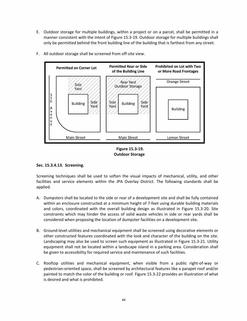
C. Overhanging elements such as awnings, canopies and signage may also occupy this zone and
in some instances may extend over the clear pedestrian throughway. See standards for
42
building ornamentation and signage requirements within the JPA Overlay district for additional guidance on required clearances.
D. Where the streetside passes a parking area, a buffer, such as a hedge or a low wall, shall be
used to screen such areas from the frontage zone and to maintain an attractive frontage along the streetside. In these instances, the frontage zone should be widened to provide space for a hedge or a low wall, installed at a minimum of three feet (3’) in height, with a visual screen up to 6 feet in height.
Sec. 15.3.4.11. Utilities.
Utilities shall be installed pursuant to all engineering standards adopted by the City of Auburndale and/or as approved by the City (consulting) engineer, except as expressly supplemented or modified under this section.
Sec. 15.3.4.11.1. Power and Communication.
A. To preserve the natural landscape and enhance the aesthetic character of the JPA Overlay
District, all new power and communication utility lines shall be installed underground. B. The undergrounding of existing overhead utility lines is encouraged as infill development
and redevelopment occurs.
Sec. 15.3.4.11.2. Stormwater.
Stormwater management systems shall respect existing standards set forth in Chapter 8, Article 2 of this Code, except as expressly supplemented or modified under the regulations established for the JPA Overlay District. Figure 15.3‐18 provides examples of desirable and undesirable stormwater ponds.
A. Stormwater ponds and open drainage ways shall, in addition to serving necessary
stormwater runoff, be designed to function as a visual amenity. B. Water tolerant trees and non‐invasive aquatic vegetation are highly encouraged to be
planted within stormwater pond(s). C. Features such as fountains may be utilized to create additional aesthetic value within
retention ponds. D. Stormwater ponds may be incorporated into the design of any required landscaping or
buffer yard. Facilities included as part of a buffer yard shall be designed to resemble natural features of the surrounding area and include a landscape buffer meeting the requirements of a “Type‐A” buffer, as shown in Figure 15.3‐10, Landscape Buffer Types. Plantings may be clustered around the pond. Species selection shall be consistent with species native to Polk County.
43
Figure 15.3‐18. Stormwater Ponds
Sec. 15.3.4.12. Outdoor Storage.
To maintain the aesthetic character of the JPA Overlay District all outdoor storage shall meet the following standards. Figure 15.3‐19 provides illustration of outdoor storage options for various lot configurations.
A. Outdoor storage shall be allowed to the rear and sides of the lot, except where prohibited. B. Outdoor storage forward of the front building line is prohibited. C. On corner lots, outdoor storage shall not extend forward of the front building line in the side
yard. D. Outdoor storage shall be prohibited on through‐lots.
44
E. Outdoor storage for multiple buildings, within a project or on a parcel, shall be permitted in a manner consistent with the intent of Figure 15.3‐19. Outdoor storage for multiple buildings shall only be permitted behind the front building line of the building that is farthest from any street.
F. All outdoor storage shall be screened from off‐site view.
Figure 15.3‐19.
Outdoor Storage Sec. 15.3.4.13. Screening.
Screening techniques shall be used to soften the visual impacts of mechanical, utility, and other facilities and service elements within the JPA Overlay District. The following standards shall be applied.
A. Dumpsters shall be located to the side or rear of a development site and shall be fully contained
within an enclosure constructed at a minimum height of 7‐feet using durable building materials and colors, coordinated with the overall building design as illustrated in Figure 15.3‐20. Site constraints which may hinder the access of solid waste vehicles in side or rear yards shall be considered when proposing the location of dumpster facilities on a development site.
B. Ground‐level utilities and mechanical equipment shall be screened using decorative elements or other constructed features coordinated with the look and character of the building on the site. Landscaping may also be used to screen such equipment as illustrated in Figure 15.3‐21. Utility equipment shall not be located within a landscape island in a parking area. Consideration shall be given to accessibility for required service and maintenance of such facilities.
C. Rooftop utilities and mechanical equipment, when visible from a public right‐of‐way or
pedestrian‐oriented space, shall be screened by architectural features like a parapet roof and/or painted to match the color of the building or roof. Figure 15.3‐22 provides an illustration of what is desired and what is prohibited.
45
D. Outdoor storage, loading and service areas shall be visual screened from off‐site view. Consideration will be given to individual site constraints in the location and screening of loading and service areas.
E. Vehicular parking areas shall be visually screened from off‐site view. Screening of parking areas
shall require a “Type‐A” landscape buffer, unless stated otherwise within specific activity centers. The landscape buffer shall be installed in accordance with the general buffering standards provided in Sec. 15.3.4.6.1. A hedge or knee wall shall also be required to be installed/constructed at a minimum of three feet (3’) in height. Construction of a knee wall shall be consistent with adjacent architecture and meet the general requirements for walls in Sec. 15.3.4.7. An example of parking area screening is provided in Figure 15.3‐23.
Figure 15.3‐20.
Dumpster Enclosure
Figure 15.3‐21.
Ground‐level Utilities Screening
46
Figure 15.3‐22.
Rooftop Utilities Screening
Figure 15.3‐23.
Vehicular Parking Area Screening
Sec. 15.3.4.14. Low Impact Development.
Sec. 15.3.4.14.1. General. All development within the JPA Overlay District is encouraged to incorporate Low Impact Development (LID) practices into design proposals. These practices help to provide mutual economic, environmental, stormwater management and aesthetic benefits. Implementation of LID practices can help to increase the developable area of a site by decreasing the size of traditional stormwater retention and detention areas. Examples of LID strategies include, but are not limited to the following.
• Permeable pavement: a hard, yet penetrable surface which reduces surface water run‐off by
allowing water to move thru the pavement surface and directly into the ground below.
• Vegetated swales and landscape islands: An alternative to traditional curb and gutter systems, where surface water run‐off is purposely directed to landscaped infiltration points/areas along streets and within parking areas.
47
• Green/Eco‐roof systems: These systems can significantly reduce the rate and quantity of
stormwater run‐off from a roof and provide buildings with thermal insulation and enhanced aesthetics.
• Bio‐retention basins and Rain gardens: Small vegetative depressions in the landscape which
collect and filter stormwater directly into the ground.
• Stormwater reuse: Engineered surface ponds and other catchment devices which store rainfall for future irrigation and potable water purposes. Small scale systems can include cisterns and rain barrels.
Sec. 15.3.4.14.2. LID Standards in Practice.
A. Eligibility. Credits and incentives for implementing LID standards may be approved as set
forth in this section, subject to the following, which must be included by an applicant as part of the development plan:
1. During the site plan and/or preliminary plat process the applicant must demonstrate
that use of LID techniques proposed in the development plan addresses at least 50 percent of the site's post‐development impervious area, calculated by a state licensed professional engineer based upon professionally acceptable methodology.
2. All LID techniques must include provisions for maintenance and enforcement to ensure that the original design remains intact and continues to provide the benefits originally designed.
3. Credits and incentives will be reviewed and may be approved, approved with conditions
based on site conditions and proposed LID techniques, or denied by the Administrative Official, or his or her designee in accordance with the requirements of this section, and subsections B. and C. below.
B. Acceptable LID techniques to receive eligible incentive credits. The following are determined to be acceptable LID techniques for which credit may be awarded:
1. Shallow retention areas. This category includes bio‐retention areas, inverted landscape
areas and planted retention areas, if these areas are less than two feet in depth and integrated within the landscaped area of a site.
2. Pervious pavement. Pervious pavement techniques utilize a variety of materials and
construction designs that allow movement of stormwater flow through sustainable material that contain pores and separation joints with eventual seepage into a base material. Types of pervious pavement include, but are not limited to, porous asphalt and concrete, plastic or concrete grid systems with gravel‐filled voids, grass pavers/turf blocks and granitic gravel. Soft gravel, asphalt millings, mulch, crushed limerick or equivalent are not considered pervious pavement.
48
3. Green roofs. A green roof is a roof of a building that is partially or completely covered with non‐invasive vegetation and a growing medium, planted over a waterproofing membrane. The purpose of a green roof is to absorb and treat rainwater, provide insulation, create habitat for wildlife and mitigate the heat island effect.
4. Resource efficient landscapes. Resource efficient landscapes are Florida‐friendly
landscapes as defined by F.S. § 373.185. Resource efficient landscapes must use in‐situ (on site) native soils, avoid soil compaction, provide wildlife habitat, reduce cover of turf grass species, use native plant species best adapted to the conditions present before planting and will not need supplemental water, fertilizer and pesticides once established.
C. Incentives for use of LID techniques. The following incentives for implementing LID
techniques may be approved during the site plan and/or preliminary plat process, where the requirements of this section are met:
1. Credit for shallow retention areas shall count toward the landscape requirements of
Chapter 10, Sec. 10.6.1.3. at a ratio of one square foot of site landscape area for every one square foot of shallow retention area provided.
2. Credit for use of pervious pavement techniques shall count toward the requirements of
development sites requiring open space (i.e., big box retail development) at a ratio of one‐half square foot of open space area for every one square foot of pervious pavement provided.
3. Credit for green roof area shall count toward the requirements of development sites
requiring open space (i.e., big box retail development) at a ratio of two square feet of open space area for every one square foot of green roof provided.
4. Credit for use of resource efficient landscapes shall count toward the requirements of
Chapter 10, Sec. 10.6.1.3. at a ratio of one and one‐half square foot of landscape area for every one square foot of resource efficient landscape provided.
5. Special consideration for exceptions to the irrigation requirements, pursuant to Sec.
15.3.4.6.2. may be given, based on alternative watering plans following best management practices in the State of Florida as determined by a landscaping professional and approved by the Administrative Official, or his or her designee.
6. The following may be granted where the minimum 50 percent capture rate of post‐
development impervious area, calculated by a state licensed professional engineer based upon professionally acceptable methodology, can be justified
a. The number of vehicular parking spaces may be reduced by 25 percent below the
standard parking requirement for the underlying zoning district. b. An increase in FAR may be granted up to the maximum bonus allotment as specified
within individual specific activity centers.
49
D. Application: Developments wishing to incorporate LID practices into a site design shall be required to coordinate with the Administrative Official, or his or her designee. Additional coordination may be required with the State of Florida and the Southwest Florida Water Management District to meet engineering and permitting requirements.
E. Maintenance: Maintenance shall be the responsibility of the facility owner unless any maintenance and easement agreements are executed.
50
Sec. 15.3.5. Big Box Retail Development. The standards established in this section pertain to big box retail developments. For purposes of defining big box retail development, a big box is considered any building designed for or devoted to retail use and which is in excess of fifty thousand (50,000) square feet measured from inside the exterior walls.
Sec. 15.3.5.1. Dimensional Standards.
Dimensional Category Yard Requirements(minimum in feet)
*Varying yard requirements may be approved through the Planned Development process. **Shall be installed in accordance with the general buffering standards provided in Sec. 15.3.4.6.1. A fence or wall shall be required when abutting residential.
Sec. 15.3.5.2. Site Coverage. Big box stores shall not cover more than fifty (50) percent of the development site. Each big box store shall reserve at least thirty (30) percent of the site as landscaped open space (such space shall not be used for buildings, parking or streets). Sec. 15.3.5.3. Design Standards.
A. Primary façade.
1. A maximum of two (2) façades will be considered primary façades, when more than two (2)
façades of a building have frontage on public or private streets. The two (2) exterior façades with the most right‐of‐way exposure will adhere, to the extent possible, to the requirements of this section.
2. Building entrances. Buildings located along a public or private street or pedestrian right‐of‐
way shall be designed with an entrance to the building or an entry courtyard facing or abutting the street or pedestrian right‐of‐way. Primary entryways shall include architectural detailing to make the entry distinctive and stand out, while remaining compatible with the overall architectural character of the building.
3. Design standards. The design of the primary façades shall include, at a minimum, two (2) of
the following design features: a. Glazing covering at a minimum thirty (30) percent of the primary façade area,
consisting of window and glazed door openings.
51
b. Projected, or recessed covered public entry providing a minimum horizontal dimension
of eight (8) feet, and a minimum area of one hundred (100) square feet.
c. Covered walkway, or arcade (excluding canvas type). The structure shall be permanent, and its design shall relate to the principal structure. The minimum width shall be eight (8) feet, with a total length measuring sixty (60) percent of the length of the associated façade.
4. Design features. Each primary façade of a building shall include at least three (3) of the
following treatments:
• Overhangs, minimum of three (3) feet. • Colonnades or arcades, a minimum of eight (8) feet clear in width. • Sculptured artwork. • Cornice minimum two (2) feet high with twelve (12) inch projection. • Peaked or curved roof forms. • Arches with a minimum twelve (12) inch recess depth. • Display windows. • Ornamental or structural architectural details, other than cornices, which are
integrated into the building structure and overall design. • Columns or pilasters.
B. Projections, Recesses and Massing.
1. Wall plane changes. Any façade with horizontal length exceeding fifty (50) linear feet shall
incorporate wall plane projections or recesses having a depth of at least three feet (3’), with a single wall plane limited to no more than sixty (60) percent of each affected façade.
2. All projections or recesses of forty feet (40’) or more, shall be considered a separate façade, and shall meet the requirements for wall plane changes.
C. Site design elements. All projects shall have a minimum of two (2) of the following:
1. Decorative landscape planters or planting areas, a minimum of five feet (5’) wide, and areas for shaded seating consisting of a minimum of one hundred (100) square feet.
2. Integration of specialty pavers, or stamped concrete along the building
perimeter walkway. Said treatment shall constitute a minimum of sixty (60) percent of walkway area.
3. Water elements, a minimum of one hundred (100) square feet in area.
4. Two (2) canopy or understory trees per landscape code requirements,
along the primary façade(s) with a minimum height of eighteen (18) feet at planting.
52
D. Entryways/Customer entrance treatments.
1. Entryway design elements are intended to give protection from the sun and adverse weather conditions. These elements are to be integrated into a comprehensive design style for the project.
2. Big box stores shall have clearly defined, highly visible, customer entrance(s). The customer
entrance shall meet the following standards:
a. An outdoor patio area shall be provided adjacent to the customer entrance, with a minimum of two hundred (200) square feet in area. The patio area shall incorporate the following:
• Benches or other seating components. • Decorative landscape planters or wing walls which incorporate landscaped areas. • Structural or vegetative shading.
b. Front entry shall be set back from a driveway or parking area by a minimum distance of
fifteen feet (15’).
E. Exterior Building Materials. Exterior building materials contribute significantly to the visual impact of buildings on the community. Materials, including building colors shall be well designed and integrated into the comprehensive design style for the project. See Sec. 15.3.4.2.D. for suggested and prohibited surface material applications.
F. Structured parking garages are permitted and shall be designed in accordance with the standards provided in Section 15.3.4.4.D.
G. Additional Standards and Requirements.
1. At least one (1) side or the front of a big box development site shall abut an arterial or
collector roadway, and at least one (1) access point for vehicular ingress and egress to and from the big box development site shall be located on an abutting arterial or collector roadway.
2. Big box developments are encouraged to maximize energy and water efficiency; protect air
and water quality; and reduce solid waste, utilizing best energy management practices as outlined by the U.S. Green Building Council (USGBC), or ENERGY STAR (joint program of the U.S. Environmental Protection Agency and the U.S. Department of Energy).
temporary/portable storage containers, and tractor‐trailer/semi‐truck parking, other than active customer and/or employee parking, are prohibited in big box development parking lots. Signs must be conspicuously displayed which state: "No overnight or long‐term parking allowed. Violators subject to fines, towing, or both."
53
Sec. 15.3.6. Village Center Development.
Sec. 15.3.6.1. Purpose and Intent.
The purpose is to create a single, unified and integrated development using new urbanism concepts and architectural plans and features that relate to pedestrian concerns and human scale. The Village Center is intended to provide a sense of place with a diverse mix of uses, housing, open space and employment opportunities. An integrated system of paths and walks shall be integrated into the master plan to promote walking and bicycling as healthy alternatives to vehicular use. An overall development plan as part of a PD will be required to assure that the Village Center will be planned and developed in a comprehensive and coordinated manner even though there may be multiple property owners.
Sec. 15.3.6.2. Dimensional Standards.
*Varying yard requirements may be approved through the Planned Development process. **See Figure 15.3‐24 for an example of building setbacks for internal streets.
Dimensional Category Dimensional Requirement
(feet) Landscape Buffer Requirement+
Minimum Maximum
Yard requirements for Internal Streets*
18 (from the back of curb)**
25 (from the back of curb)**
N/A
Side yard requirements 0 N/A Block Length 400 (maximum) N/A Minimum Building & Parking Yard Requirements From Village Center Boundary
25 (Minimum) Type‐B
54
+ Shall be required between any non‐residential use that directly abuts residential and shall be installed in accordance with the general buffering standards provided in Sec. 15.3.4.6.1.
A. Maximum Building Height. The maximum building heights for uses within the Village Center shall be seventy feet (75’) or seven stories.
B. Maximum Impervious Surface Area. The maximum Impervious Surface Area (ISR) shall be 80 percent.
Figure 15.3‐24.
Building Setbacks for Internal Streets
Sec. 15.3.6.3. Design Standards.
Development within the Village Center shall adhere to all Development Guidelines and Design Standards in Sec. 15.3.3. and Sec. 15.3.4, in addition to the standards provided below. If there is a conflict between these sections, the provisions of this section shall apply.
A. The primary entry road into the Village Center shall have a pedestrian‐friendly “Main Street”
appearance and not a strip commercial type approach of building organization.
B. The identity of the “main street” shall be reinforced by a pedestrian oriented streetscape including wide sidewalks, a coordinated street lighting scheme and street trees. The sidewalks should facilitate walking, window shopping, and dining. The architecture, hardscape, landscape and activities should be interesting to encourage community interaction.
55
C. The primary pedestrian entry shall be from the street front of a building. Secondary entries are permitted on the sides of buildings. All service shall be in the rear of buildings.
D. The Village Center shall include a square or plaza with walkways, landscaping, benches and
water or public art feature to encourage community interaction. The square or plaza shall be a clear focal point for the center. The square or plaza shall be sized to have an appropriate relationship with surrounding buildings to have an intimate, human scale. Any public open space shall be accessible via pedestrian connections from public sidewalks or parking areas.
E. The streetside corridor shall be a minimum of eighteen feet (18’) wide from the back of the
curb to the face of the building. See Figure 15.3‐24 for an example of streetside setbacks. The streetside corridor shall be established per the Streetside Principles provided in Sec. 15.3.4.10.
F. Building ornamentation, such as balconies, awnings, covered entrances, roof overhangs and
other such design features may encroach into the frontage zone or over sidewalks. See additional requirements for Building Ornamentation in Sec. 15.3.4.9.
G. Appropriate scale canopy street trees shall be planted thirty‐five (35) to forty‐five feet on
center within the furnishings zone. Tree grates or guards shall be used.
H. Benches and trash receptacles of a consistent design may be placed in the furnishings zone. Other furnishings may be appropriate such as planters, large pots containing plants, kiosks, or public art. Coordinated seasonal banners of a consistent design and/or hanging plant baskets may be attached to light poles along the streets. Advertising for individual businesses may not be affixed to light poles or benches.
I. Parking.
1. Parking areas shall be located to the rear or side‐street or internal street rather than on “main street,” unless on‐street parking is utilized as part of the development plan. When parking areas are located adjacent to a side street or internal street, the parking area shall be screened in accordance with Sec. 15.3.4.13.E.
2. On‐street parking may be established on all streets in the Village Center. See additional requirements for On‐street Parking in Sec. 15.3.4.4.1.
3. Structured parking garages are permitted and shall be designed in accordance with the
standards provided in Section 15.3.4.4.D. Parking garages may face the “main street” but vehicle access to the parking garage shall be accommodated from a rear or side street.
56
Sec. 15.3.7. Activity Centers. A. General. The development of “Activity Centers” is a strategic part of the implementation and
realization of the JPA Overlay District. Activity Centers are focused areas of development designed to promote specific outcomes by providing for a range of activities and a mix of development types. The standards contained herein have been designed to promote the following:
• New places for employment; • New places to shop, eat, and entertain; • A range of housing types and configurations; • New destinations within a short distance of existing neighborhoods and amenities; • Opportunities to increase walking, biking, and transit use; and • More efficient use of existing public infrastructure.
B. Applicability. The following Activity Centers are identified within the JPA Overlay District:
• Regional & Tourism Commercial Activity Centers • Commercial Activity Centers. These include the following:
o Community Activity Centers o Neighborhood Activity Centers o Commercial Corridors o Convenience Centers
• Business Park Center
Sec. 15.3.7.1. Regional & Tourism Commercial Activity Centers.
Sec. 15.3.7.1.1. Purpose and Intent.
The purpose and intent of the Regional Activity Center (RAC) and Tourism Commercial Center (TCC) is to promote and facilitate mixed‐use developments containing residential, commercial
57
and office uses, hospitality uses, regional shopping centers, and other regional and tourist‐based attractors, to accommodate regional needs. Sec. 15.3.7.1.2. Dimensional Standards.
Dimensional Category Residential Non‐Residential
Landscape Buffer Requirement** Min.
(feet)Max. (feet)
Min. (feet)
Max. (feet)
Interior of site
Front yard requirement* 5 15 0 15 N/A Rear yard requirement* 10 0 N/A Side yard requirement* 5 10 0 N/A Separation of residential units/buildings 10 N/A N/A
Separation of nonresidential and residential uses 50 Type‐B
Yard requirement (abutting a public right‐of‐way) 25 (minimum) Type‐B
*Varying yard requirements may be approved through the Planned Development process. ** Shall be installed in accordance with the general buffering standards provided in Sec. 15.3.4.6.1. A fence or wall
shall be required when abutting residential.
A. All sides of a lot adjacent to streets shall be considered frontage.
C. Maximum Floor Area Ratio. The maximum Floor Area Ratio (FAR) for non‐residential
development is 0.50. FAR bonuses may be granted, up to an FAR of 1.0, when LID standards are implemented. All density and intensity regulations specific to areas located within the Green Swamp Area of Critical State Concern supersede any such regulations in this section.
D. Standards for “Big Box” Retail Development. Design standards for big box retail
development shall meet specific standards set forth in Sec. 15.3.5.
E. Development Standards for “Village Centers. Village Center style developments shall meet specific development requirements set forth in Sec. 15.3.6.
Sec. 15.3.7.1.3. Design Standards.
A. The primary entryway/boulevard into an RAC or TCC shall be landscaped, and may include a
landscaped entryway median and identification signage consistent with Signage and Landscaping requirements under Sec. 15.3.4.5 and Sec. 15.3.4.6.
58
B. Parking.
1. Where parking areas abut a street, the parking area shall be screened in accordance with Sec. 15.3.4.13.E.
2. On‐street parking may be established within the RAC and TCC. See additional requirements for On‐street Parking in Sec. 15.3.4.4.1.
3. Structured parking garages are permitted and shall be designed in accordance with the
standards provided in Section 15.3.4.4.D.
59
Sec. 15.3.7.2. Commercial Activity Centers.
Sec. 15.3.7.2.1. Purpose and Intent.
Commercial Activity Centers include Community Activity Centers, Neighborhood Activity Centers, Commercial Corridors and Convenience Centers. These activity centers are intended to be designed to accommodate the shopping, business and service needs of residents of the City and surrounding area population. An integrated system of paths and walks shall be integrated into these development areas to provide pedestrian access and connectivity to the Greater Auburndale Area.
*Varying yard requirements may be approved through the Planned Development process. + Shall be required between any non‐residential use that directly abuts residential and shall be installed in accordance with the general buffering standards provided in Sec. 15.3.4.6.1. Yard requirements for building setbacks will need to adjust accordingly to accommodate landscape buffer requirements.
A. All sides of a lot adjacent to streets shall be considered frontage.
60
B. Maximum Building Height. The maximum building height for non‐residential uses shall be 75‐feet.
C. Maximum Floor Area Ratio. The maximum Floor Area Ratio (FAR) for non‐residential
development is 0.50. FAR bonuses may be granted, up to an FAR of 1.0, when LID standards are implemented. All density and intensity regulations specific to areas located within the Green Swamp Area of Critical State Concern supersede any such regulations in this section.
D. Standards for “Big Box” Retail Development. Design standards for big box retail
development shall meet specific standards set forth in Sec. 15.3.5.
E. Development abutting a collector roadway shall provide a landscape strip at least five feet (5’) wide with a minimum of one (1) canopy or understory tree and seven (7) shrubs for each 30 linear feet of collector roadway frontage, or fraction thereof. Such plantings shall be coordinated so as to complement building entranceways, storefront windows, signage and other architectural features of the streetside building façade. Landscape buffers for big box retail development shall adhere to specific buffering requirements set forth for in Sec. 15.3.5.
Sec. 15.3.7.2.3. Design Standards.
Development within Commercial Activity Centers shall adhere to all Development Guidelines and Design Standards in Sections 15.3.3 and 15.3.4, in addition to the standards provided below.
A. Balconies, awnings, covered entrances, roof overhangs and other such design features are
encouraged and may encroach into the frontage zone of sidewalks.
B. Benches of a consistent design may be placed in the furnishings zone. Other furnishings may be appropriate such as planters, large pots containing plants, kiosks, or public art. Coordinated seasonal banners of a consistent design and/or hanging plant baskets may be attached to light poles along the streets. Advertising for individual businesses may not be affixed to light poles or benches.
C. Parking
1. Parking is encouraged to be located to the rear or side‐street or internal street rather
than the main frontage roadway. A single row of parking spaces may be established within the front yard of the development site.
2. Where parking areas abut a street, the parking area shall be screened in accordance
with Sec. 15.3.4.13.E.
3. Structured parking garages are permitted and shall be designed in accordance with the standards provided in Section 15.3.4.4.D.
D. Signage. Signage shall meet all applicable sign requirements provided in Sec. 15.3.4.5.
61
Sec. 15.3.7.3. Business Park Center
Sec. 15.3.7.3.1. Purpose and Intent. Business Park Centers (BPC) are intended to provide opportunities for employment centers, designed in an attractive park‐like environment with landscaping and architectural amenities that create a sense of place and an aesthetically attractive urban development. The BPC is intended for land use activities conducted entirely within enclosed structures with the exception of loading, unloading, and outdoor storage activities, where permitted.
Sec. 15.3.7.3.2. Dimensional Standards.
*Varying yard requirements may be approved through the Planned Development process. ** Shall be installed in accordance with the general buffering standards provided in Sec. 15.3.4.6.1. A fence or wall shall be required when abutting residential.
+Buildings may require greater separation depending on building location(s), size and scale.
A. All sides of a lot adjacent to streets shall be considered frontage.
Dimensional Category Non‐Residential
(feet) Landscape Buffer Requirement**
Minimum Yard requirement along arterial or collector roadways, unless otherwise stated*
150 Type‐C (minimum 35‐feet)
Yard requirement along Interstate‐4* 50 Type‐C (minimum 25‐feet)
Yard requirement from internal roadway* 45 Type‐C
(minimum 25‐feet) Building separation requirement*+ 10 N/A
62
B. Maximum Building Height. The maximum building height for non‐residential uses shall be
75‐feet.
C. Maximum Floor Area Ratio. The maximum Floor Area Ratio (FAR) for non‐residential development is 0.75. FAR bonuses may be granted, up to an FAR of 1.5, when LID standards are implemented. All density and intensity regulations specific to areas located within the Green Swamp Area of Critical State Concern supersede any such regulations in this section.
Sec. 15.3.7.3.3. Design Standards.
Development within the Business Park Centers shall adhere to all Development Guidelines and Design Standards in Sections 15.3.3 and 15.3.4, in addition to the standards provided below. The following design standards are intended to provide compatibility with and protection to surrounding residential and commercial properties by minimizing, noise, glare, vibration, odors, airborne particulate, and toxic substances.
A. The primary entry shall be from the street front of a building. Secondary entries are
permitted on the sides of buildings.
B. All service, including truck courts, loading and unloading areas are encouraged to be located to the sides and rear of buildings, along the Interstate‐4 corridor, or internal to the development site.
C. Loading docks and overhead service doors shall be designed to be compatible with the
architecture of the principal building. Loading docks shall be screened from all frontage roads, including Interstate‐4. Screening shall require a “Type C” landscape buffer, a minimum of 25‐feet in width, and shall be installed in accordance with the general buffering standards provided in Sec. 15.3.4.6.1.
D. Treatment of all screen walls and service areas shall be compatible with the architecture of
the principal building. All roof‐mounted mechanical equipment shall be screened from view by a parapet wall along the top of the roof.
E. Outdoor Storage. Outdoor storage is only permitted as an accessory use and shall comply
with the requirements of Sec. 15.3.4.12. In addition, outdoor storage shall meet the following requirement:
1. Be located behind the rear building line and adequately buffered from users of any
roadway and adjacent residents.
2. Be at a minimum of 50 feet from any lot line.
3. All speakers shall be setback 100 feet from any adjacent or adjoining residential use or residential land use district.
4. All speakers shall be directed away from any adjacent or adjoining residential use or
residential land use district.
63
Sec. 15.3.7.3.4. Building Design and Architectural Standards.
A. Exterior Building Materials. Exterior building materials contribute significantly to the visual
impact of buildings on the community. Materials, including building colors shall be well designed and integrated into the comprehensive design style for the project. See Sec. 15.3.4.2.D. for suggested and prohibited surface material applications.
B. Primary façades.
1. Buildings located along a public or private street or pedestrian right‐of‐way shall be
designed with an entrance to the building or an entry courtyard facing or abutting the street or pedestrian right‐of‐way. Primary entryways shall include architectural detailing to make the entry distinctive and stand out, while remaining compatible with the overall architectural character of the building.
2. Design features. The design of the primary façades shall include the following:
a. Glazing covering at a minimum thirty (30) percent of the primary façade area, consisting of window and glazed door openings.
b. Projected, or recessed covered public entry providing a minimum horizontal dimension of eight (8) feet, and a minimum area of one hundred (100) square feet.
c. Clearly identifiable separation lines between the first and upper floors shall be
expressed through the use of color and/or other architectural treatments. Separation lines shall have a minimum vertical dimension 12 inches (12”), projected outward or recessed from the wall two inches (2”).
d. A kickplate shall be applied at the base of the building with a minimum vertical
dimension of three feet (3’). The kickplate shall be expressed with a textured building material.
e. Varying roof heights shall be applied to provide additional visual interest.
Architectural rhythm should be considered in the design of roof heights and should be coordinated as best as possible with those of adjacent existing or planned buildings.
3. Variation in massing.
a. A single, large, dominant building mass shall be avoided. Changes in mass shall be
related to entrances, the integral structure and the organization of interior spaces and activities, and not merely for cosmetic effect. False fronts or parapets create insubstantial appearance and are discouraged.
b. Any façade with a horizontal length or width exceeding fifty (50) linear feet shall
incorporate wall plane projections or recesses having a depth of at least three (3)
64
feet. Each variation in the building’s façade shall not exceed sixty (60) percent of the total horizontal length or width of the building.
4. Site design elements. All projects shall have a minimum of two (2) of the following:
a. Decorative landscape planters or planting areas, a minimum of five (5) feet wide,
and areas for shaded seating consisting of a minimum of one hundred (100) square feet.
b. Integration of specialty pavers, or stamped concrete along the building perimeter walkway. Said treatment shall constitute a minimum of sixty (60) percent of walkway area.
c. Water elements, a minimum of one hundred (100) square feet in area.
d. Two (2) canopy or understory trees per landscape code requirements, along the
primary façade(s) with a minimum height of eighteen (18) feet at planting.
5. Windows and entrances.
a. Windows shall not be false or applied. Spandrel panels in curtain wall assembly are allowed, but may not be included in the maximum glazing required for primary façade.
b. The first floor of primary façades shall utilize transparent windows for no less than
thirty (30) percent of the horizontal length of the building façade. The bottoms of such windows shall be no more than three (3) feet above the walkway grade and the tops of such windows shall not be less than eight (8) feet above the walkway grade.
6. Signage. Signage shall meet all applicable sign requirements provided in Sec. 15.3.4.5.
7. Parking. Parking shall be provided to meet the needs of the uses in an efficient manner
that best suits the community collectively through optional methods such as shared parking and alternative pavement.
a. Parking spaces may be established within the front yard of the development site. b. Where parking areas abut a street, a “Type‐C” buffer, with a minimum width of 25‐
feet shall be required. The buffer shall be installed in accordance with the general buffering standards provided in Sec. 15.3.4.6.1.
c. Structured parking garages are permitted and shall be designed in accordance with
the standards provided in Section 15.3.4.4.D.
d. All landscaping within parking areas shall meet the Landscaping requirements in Sec. 15.3.4.6.
65
e. Florida‐Friendly landscaping and native plant materials are encouraged to be incorporated into the parking lot landscaping.
f. No more than 50 percent of the required plantings shall be of any one species.
g. The minimum landscaping for each lot shall be provided within the interior of a
required paved off‐street parking area as follows:
1. A parking island shall be required for each 16 parking spaces. 2. Each aisle of parking spaces shall be terminated by landscaped islands which
measure not less than nine feet in width, as measured from the face of curb to face of curb, and not less than 18 feet in length, At least one canopy tree shall be planted in each terminal island.
3. Mandatory terminal islands shall be surrounded with a continuous raised curb. 4. Landscaped divider medians may be used to meet interior landscape
requirements. If divider medians are used, they shall form a continuous landscaped strip between abutting rows of parking spaces. The minimum width of divided medians shall be a minimum six foot wide, as measured from the face of curb to face of curb. One under story tree shall be planted for each 30 linear feet of divided median, or fraction thereof. Trees in a divided median may be planted individually or in clusters. The maximum spacing between clusters shall be 60 feet.
5. A minimum six foot wide divider median, as measured from face of curb to face
of curb, shall be required every fourth bay of parking. A minimum of one understory tree shall be planted for each 30 linear feet of divider median. An alternative option, three diamond shaped islands may be substituted for the continuous six foot wide divider median.
6. Optional interior islands and divider medians shall be protected by curbing or
wheel stops. 7. Each parking bay shall have no more than ten continuous parking spaces
unbroken by a landscape island that shall be the width of a parking space, as measured from face of curb to face of curb.
8. Landscape areas shall be located in such a manner as to divide and break up the
expanse of paving and to guide traffic flow. 9. LID standards are encouraged to be used within parking areas.
66
Sec. 15.3.8. Corridors
Sec. 15.3.8.1. Purpose and Intent.
To provide a unified, aesthetically landscaped thoroughfare along arterial or collector roadway segments between established activity centers within the JPA Overlay District. The intent of these regulations is to create a complementary sense of place, outside of the identified activity center zones, which bind together the overall theme and character of the entire overlay district. Design standards established for those lands that develop along such thoroughfares shall contribute to the attractiveness and aesthetic quality of the district, further enhancing the economic vitality of the area.
Sec. 15.3.8.2. Applicability.
The standards provided herein shall apply to the perimeter treatments of developments that directly abut a public right‐of‐way, except as expressly supplemented or modified for specific activity centers located within the JPA Overlay District. The provisions in this section do not apply to individual single‐ and two‐family residential lot development.
Sec. 15.3.8.2. Corridor Landscaping Standards.
Corridor landscaping shall be interpreted to mean the buffer yard of a development site that is established along a public right‐of‐way and not within an identified activity center. The following standards shall apply.
A. A “Type‐C” landscape buffer is required to be installed along all designated arterial and collector
roadways and shall be installed in accordance with the general buffering standards provided in Sec. 15.3.4.6.1.
B. Plantings materials, including installation and irrigation shall meet the Landscaping requirements provided in the Sec. 15.3.4.6.
C. No more than 50% of the required plantings shall be of any one species.
67
D. No fence, wall, vegetative planting, earthen berm, or other visual obstruction shall be
established near intersecting roadways and driveways, where such buffering would impede on clear visibility and the safe movement of pedestrian and vehicular traffic.
E. Buffer yards shall not occupy any portion of an existing, dedicated, or reserved public right‐of‐
way, unless a landscape maintenance agreement is approved by the City.
F. Residential subdivisions shall be required to provide a perimeter fence or wall as part of the buffer yard requirement along public rights‐of‐way.
G. Where a fence or wall is used as part of a buffer yard the following shall apply:
1. Construction and installation shall meet the design standards for Fences and Walls as
provided in Sec. 15.3.4.7.
2. Fences and walls shall be a minimum of six feet (6’) in height and a maximum of eight feet (8’) in height.
3. Trees and other vegetative plantings may be clustered so as to accentuate articulations of
the fence or wall.
4. No perimeter fence or wall shall be located nearer than ten feet (10’) of a property line, public sidewalk or other pedestrian pathway.
H. Where proper drainage of a development site allows, stormwater ponds may be established as
part of the buffer yard. Where a stormwater pond is incorporated as part of the buffer yard, the following shall apply:
1. The design shall meet the Stormwater requirements as established in Sec. 15.3.4.11.2.
2. The buffer yard area shall be a minimum of fifteen feet (15’) wide.
3. A minimum of two (2) canopy trees and three (3) understory trees shall be planted for every
thirty‐five feet (35’) of linear stormwater pond established. Additional trees may be planted within or adjacent to the stormwater pond.