35
Transmissions Pat Willoughby Wednesday Section 2/16/2005

Transmissions
Pat WilloughbyWednesday Section
2/16/2005
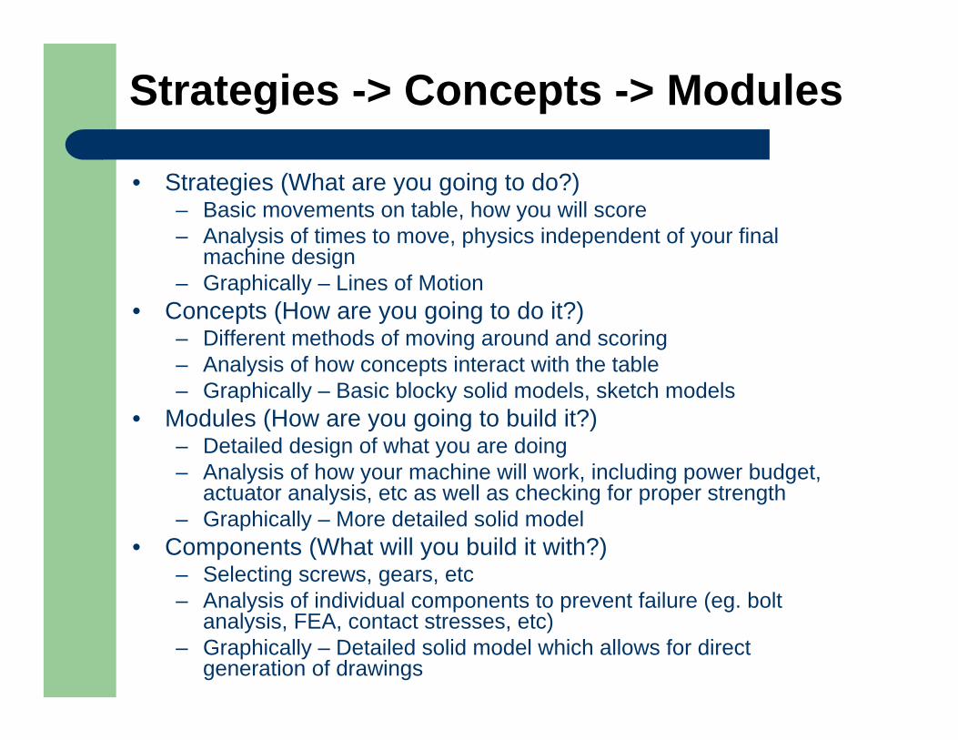
Strategies -> Concepts -> Modules
• Strategies (What are you going to do?)– Basic movements on table, how you will score– Analysis of times to move, physics independent of your final
machine design– Graphically – Lines of Motion
• Concepts (How are you going to do it?)– Different methods of moving around and scoring– Analysis of how concepts interact with the table– Graphically – Basic blocky solid models, sketch models
• Modules (How are you going to build it?)– Detailed design of what you are doing– Analysis of how your machine will work, including power budget,
actuator analysis, etc as well as checking for proper strength– Graphically – More detailed solid model
• Components (What will you build it with?)– Selecting screws, gears, etc– Analysis of individual components to prevent failure (eg. bolt
analysis, FEA, contact stresses, etc)– Graphically – Detailed solid model which allows for direct
generation of drawings
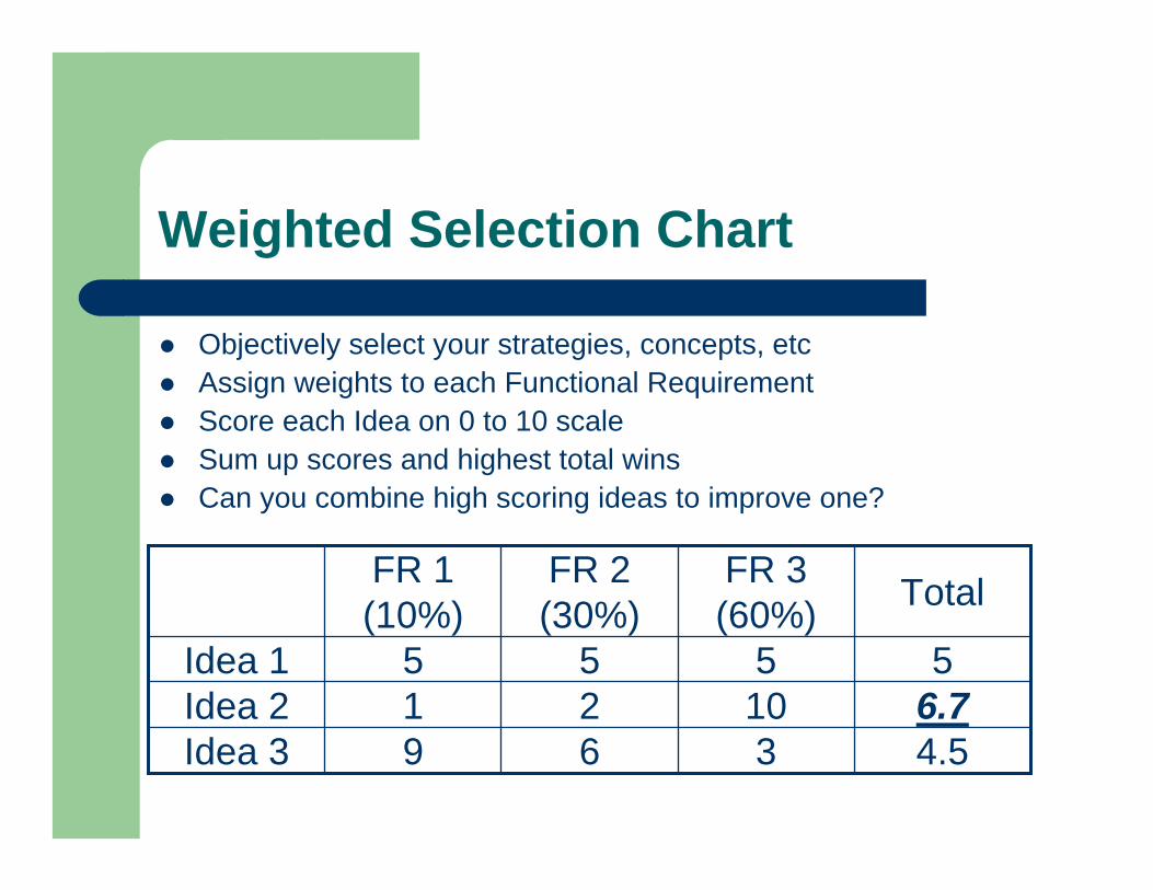
Weighted Selection Chart
Objectively select your strategies, concepts, etcAssign weights to each Functional RequirementScore each Idea on 0 to 10 scaleSum up scores and highest total winsCan you combine high scoring ideas to improve one?
4.5369Idea 36.71021Idea 25555Idea 1
TotalFR 3 (60%)
FR 2 (30%)
FR 1 (10%)
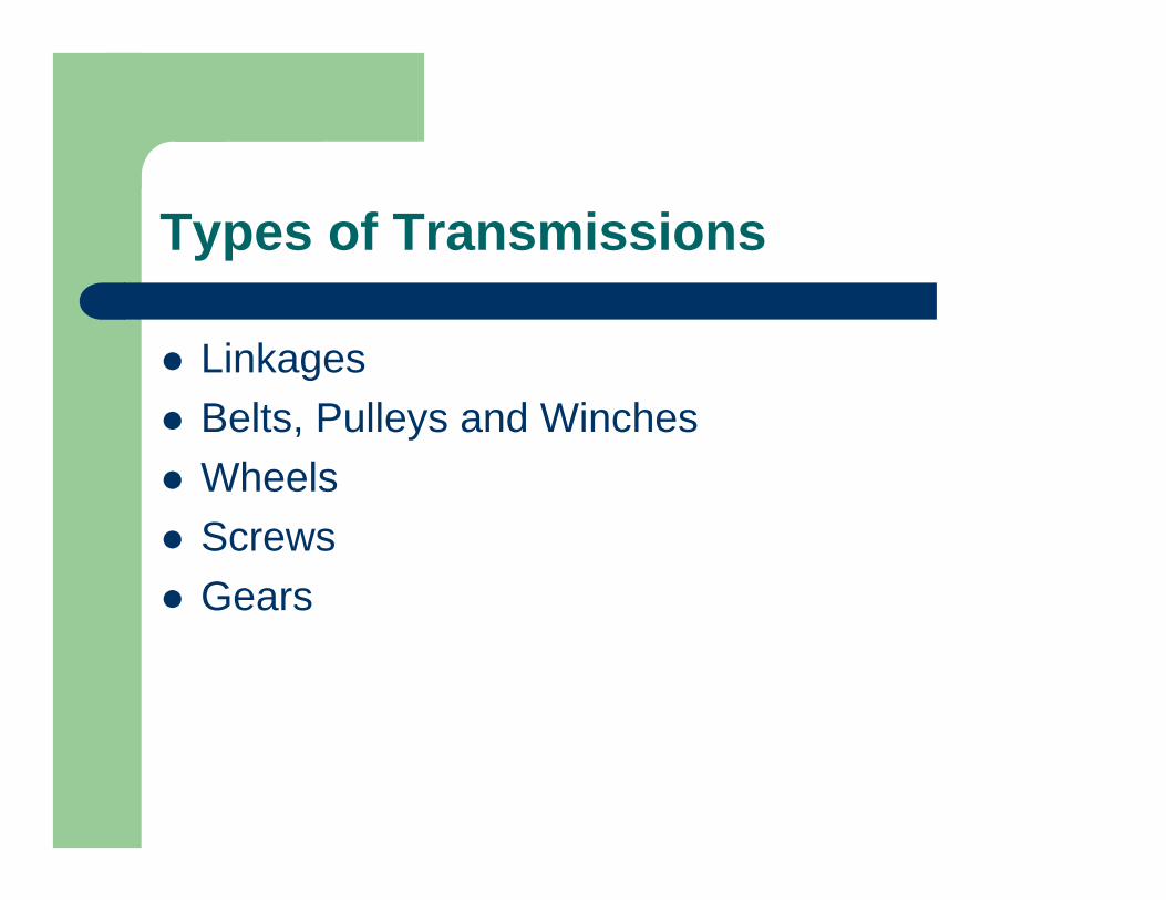
Types of Transmissions
LinkagesBelts, Pulleys and WinchesWheelsScrewsGears

Belt Basics
Basics – Power, Torque, VelocityMore Details – Spreadsheets!
DF Γ=
2
R1Rinωout, Γout
Vbelt = Routωout
Vbelt = Rinωin
ωin, Γin
Powerout = Powerin
speedoutTorqueout = speedinTorquein
Γout = ωinΓin/ωout
2DTF µ
=
Toothed Belt:
Flat Belt:
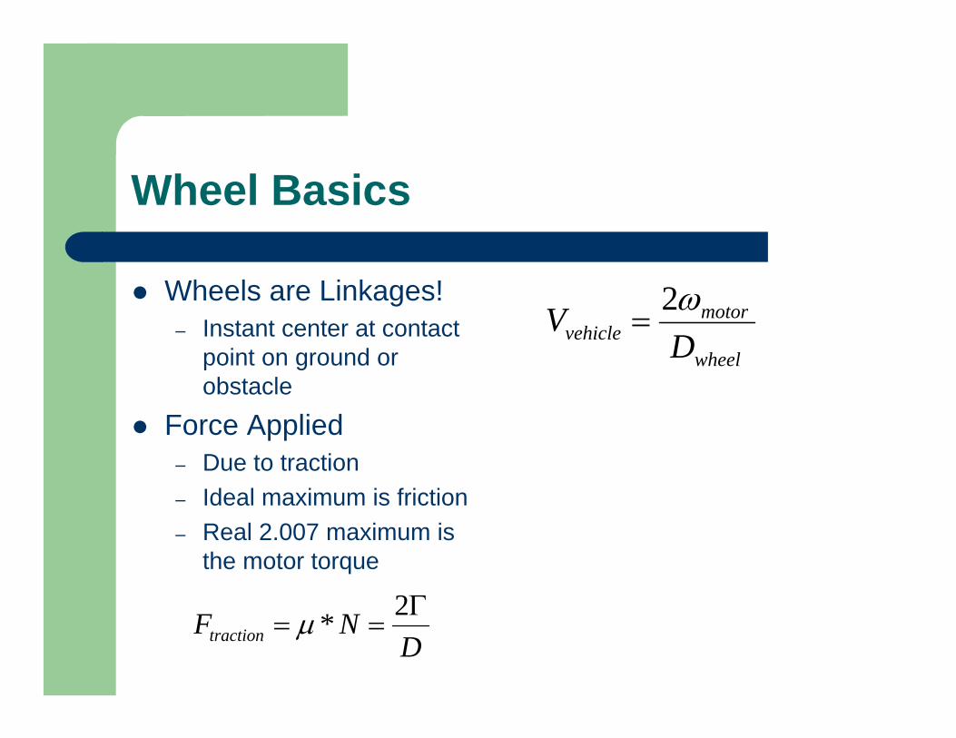
Wheel Basics
Wheels are Linkages!– Instant center at contact
point on ground or obstacle
Force Applied– Due to traction– Ideal maximum is friction– Real 2.007 maximum is
the motor torque
wheel
motorvehicle D
V ω2=
DNFtraction
Γ==
2*µ

What do lead screws and gears do?
Lead or Ball screws – convert rotary motion from a motor to linear motion along the screwGears – can convert rotary motion to linear or rotary motion at the same or a different angleTransmit power through changes in force and velocity
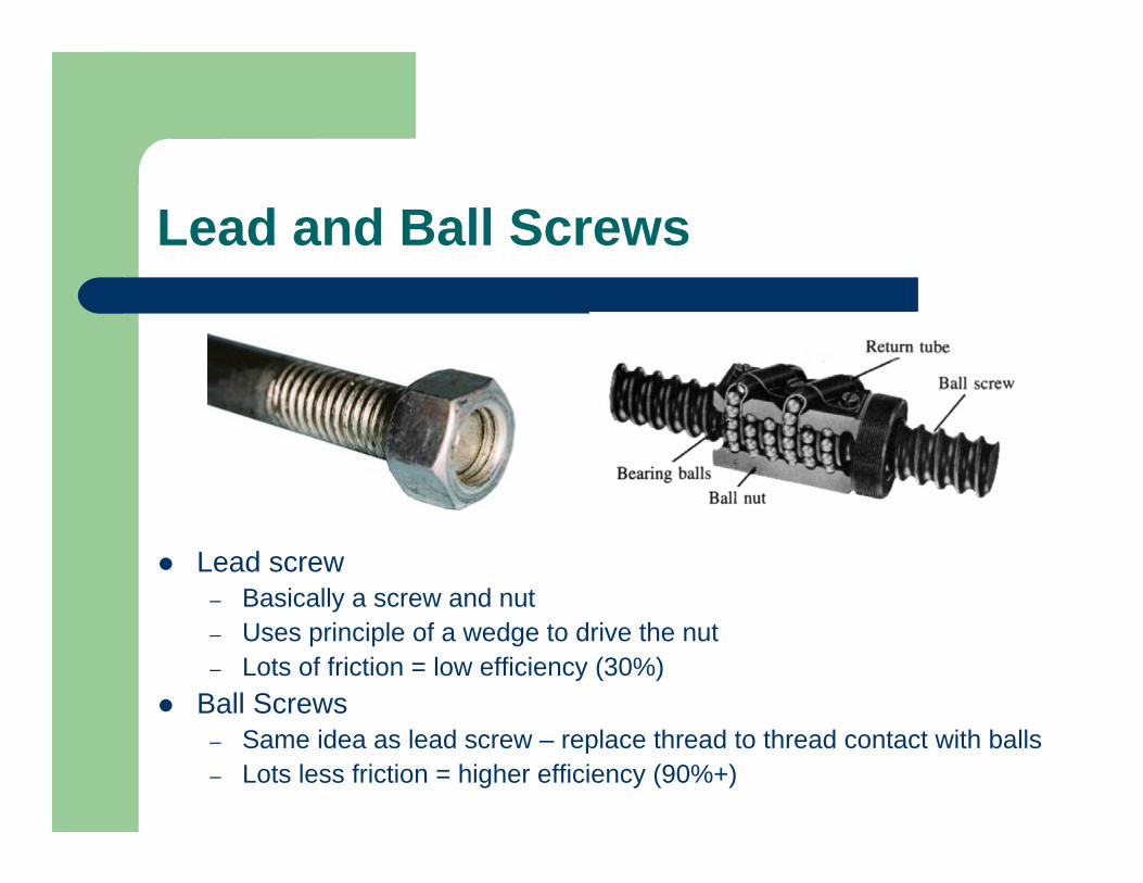
Lead and Ball Screws
Lead screw – Basically a screw and nut– Uses principle of a wedge to drive the nut– Lots of friction = low efficiency (30%)
Ball Screws– Same idea as lead screw – replace thread to thread contact with balls– Lots less friction = higher efficiency (90%+)
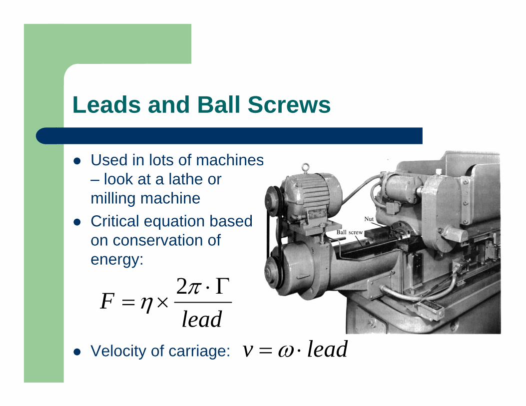
Leads and Ball Screws
Used in lots of machines – look at a lathe or milling machineCritical equation based on conservation of energy:
Velocity of carriage:
leadF Γ⋅
×=πη 2
leadv ⋅= ω
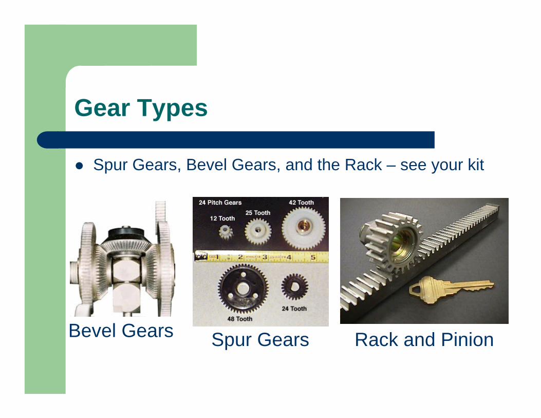
Gear Types
Spur Gears, Bevel Gears, and the Rack – see your kit
Bevel Gears Rack and PinionSpur Gears
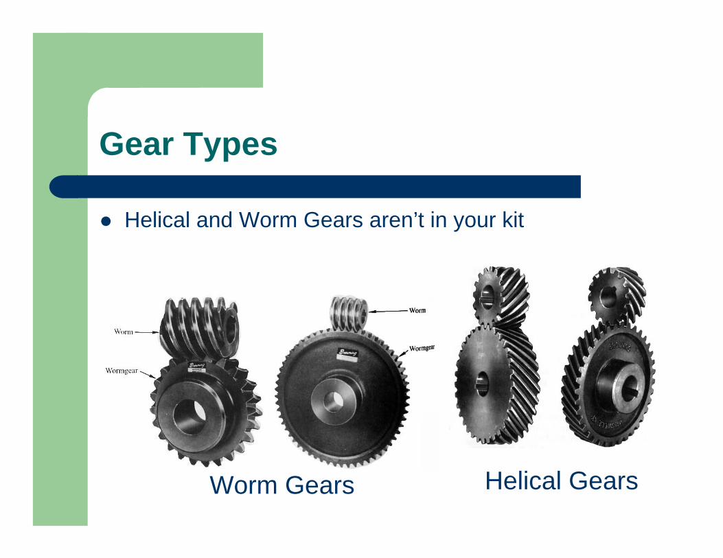
Gear Types
Helical and Worm Gears aren’t in your kit
Worm Gears Helical Gears
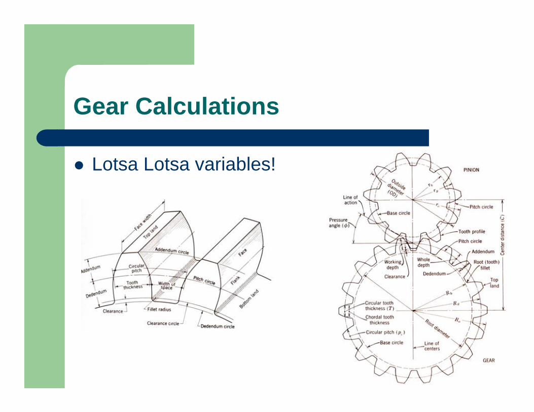
Gear Calculations
Lotsa Lotsa variables!
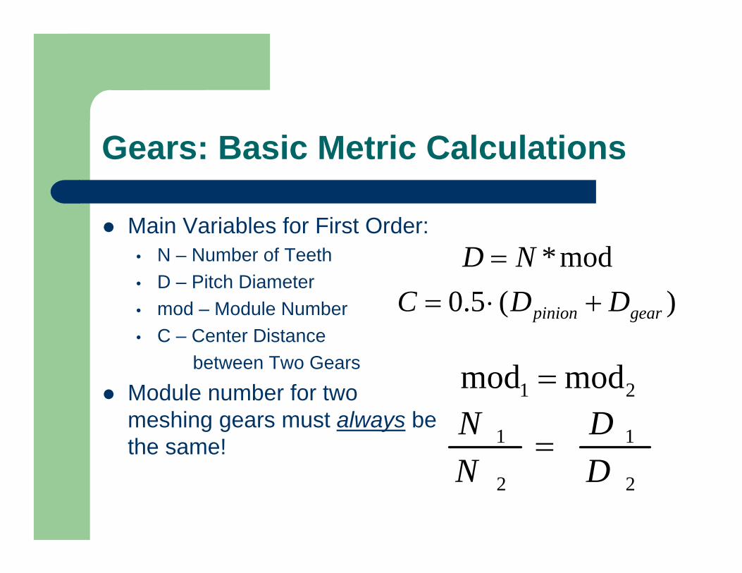
Gears: Basic Metric Calculations
Main Variables for First Order:• N – Number of Teeth• D – Pitch Diameter• mod – Module Number• C – Center Distance
between Two Gears
Module number for two meshing gears must always be the same!
)(5.0mod*
gearpinion DDCND
+⋅==
2
1
2
1
DD
NN
=
21 modmod =
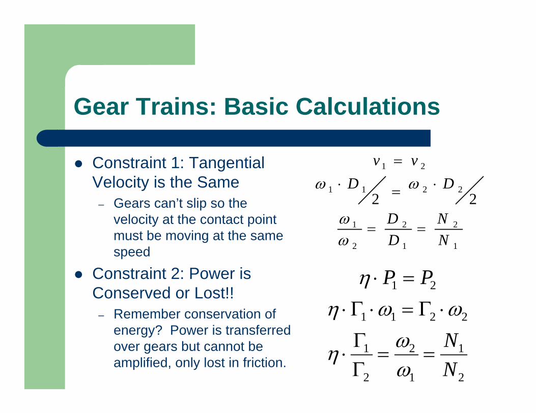
Gear Trains: Basic Calculations
Constraint 1: Tangential Velocity is the Same
– Gears can’t slip so the velocity at the contact point must be moving at the same speed
Constraint 2: Power is Conserved or Lost!!
– Remember conservation of energy? Power is transferred over gears but cannot be amplified, only lost in friction.
1
2
1
2
2
1
2211
21
22
NN
DD
DDvv
==
⋅=⋅=
ωω
ωω
2
1
1
2
2
1
2211
21
NN
PP
==ΓΓ⋅
⋅Γ=⋅Γ⋅=⋅
ωωη
ωωηη
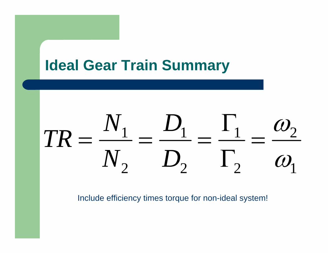
Ideal Gear Train Summary
1
2
2
1
2
1
2
1
ωω
=ΓΓ
===DD
NNTR
Include efficiency times torque for non-ideal system!

But what about the minus signs?
To get proper signs:– Follow through with
signs or arrows as shown in lecture notes
– For simple systems, do it graphically with a “virtual belt”
Gears: Selection of Parameters
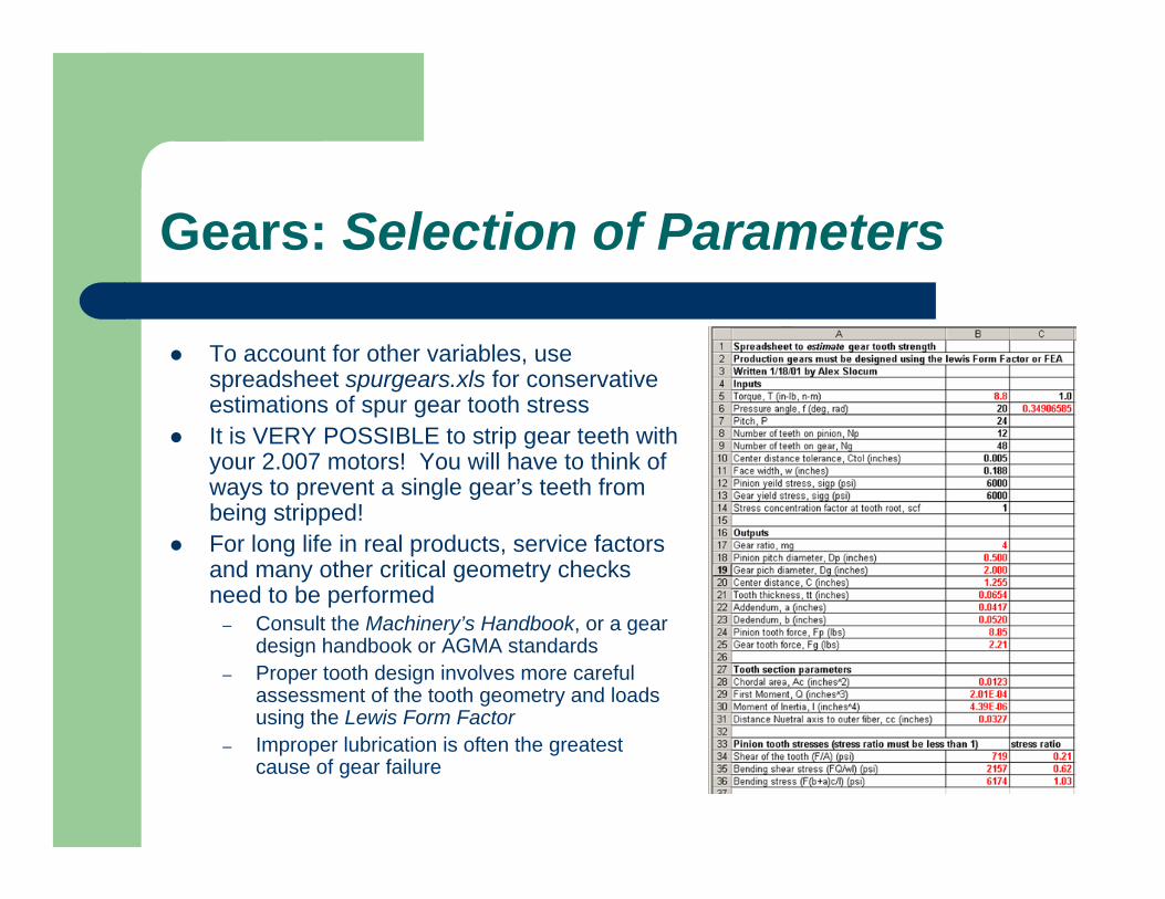
To account for other variables, use spreadsheet spurgears.xls for conservative estimations of spur gear tooth stressIt is VERY POSSIBLE to strip gear teeth with your 2.007 motors! You will have to think of ways to prevent a single gear’s teeth from being stripped!For long life in real products, service factors and many other critical geometry checks need to be performed
– Consult the Machinery’s Handbook, or a gear design handbook or AGMA standards
– Proper tooth design involves more careful assessment of the tooth geometry and loads using the Lewis Form Factor
– Improper lubrication is often the greatest cause of gear failure
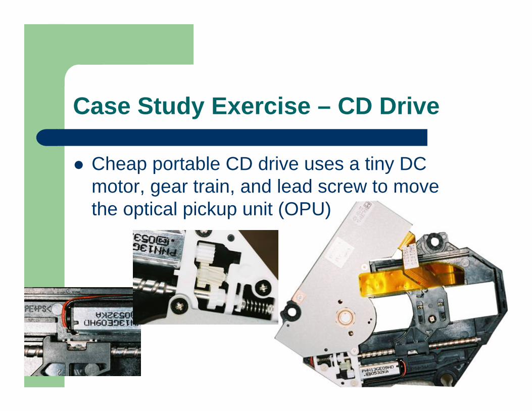
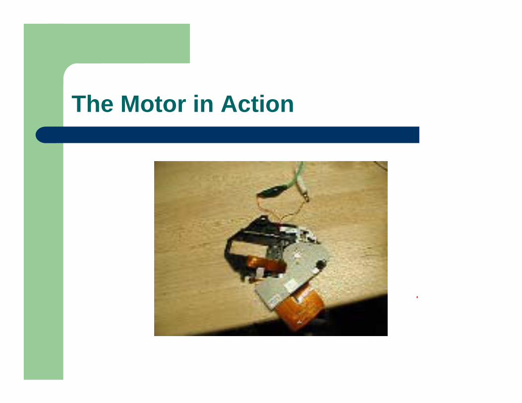
Case Study Exercise – CD Drive
Cheap portable CD drive uses a tiny DC motor, gear train, and lead screw to move the optical pickup unit (OPU)
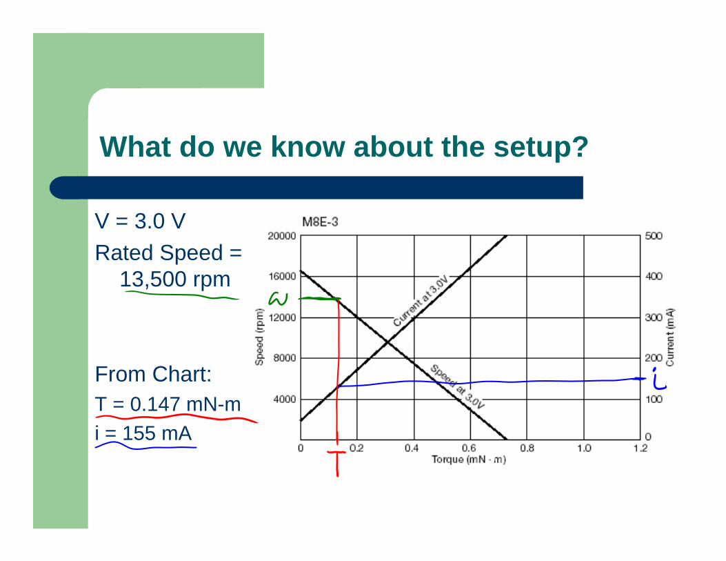
What do we know about the setup?
V = 3.0 VRated Speed =
13,500 rpm
From Chart:T = 0.147 mN-mi = 155 mA
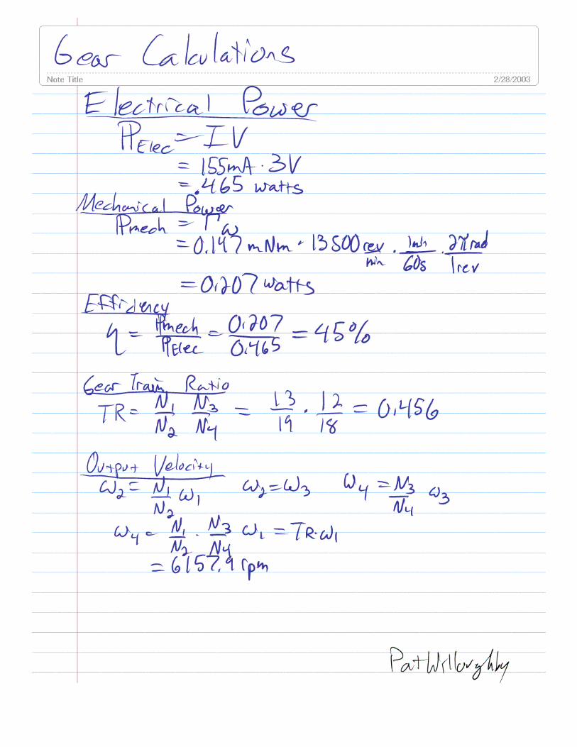
Power
• What is the electrical and mechanical power of the motor?
• What is the motor efficiency?
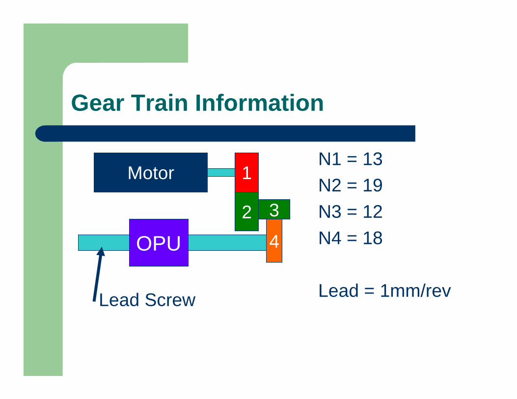
Gear Train Information
N1 = 13N2 = 19N3 = 12N4 = 18
Lead = 1mm/rev
Motor 1
2 3
4OPU
Lead Screw
Gear Train Calcs.
• What is the Gear Train Ratio?
Gear Train Calcs.
• What is the output velocity of the train?

Gear Train Calcs.
• What is the output torque of the train?
Lead Screw Calcs.
• What is the output force of the screw?

Lead Screw Calcs.
• What is the output velocity of the screw?
The Motor in Action
Output Power
• What is the output power of the screw?
System Efficiency
• What is system efficiency (2 ways)?

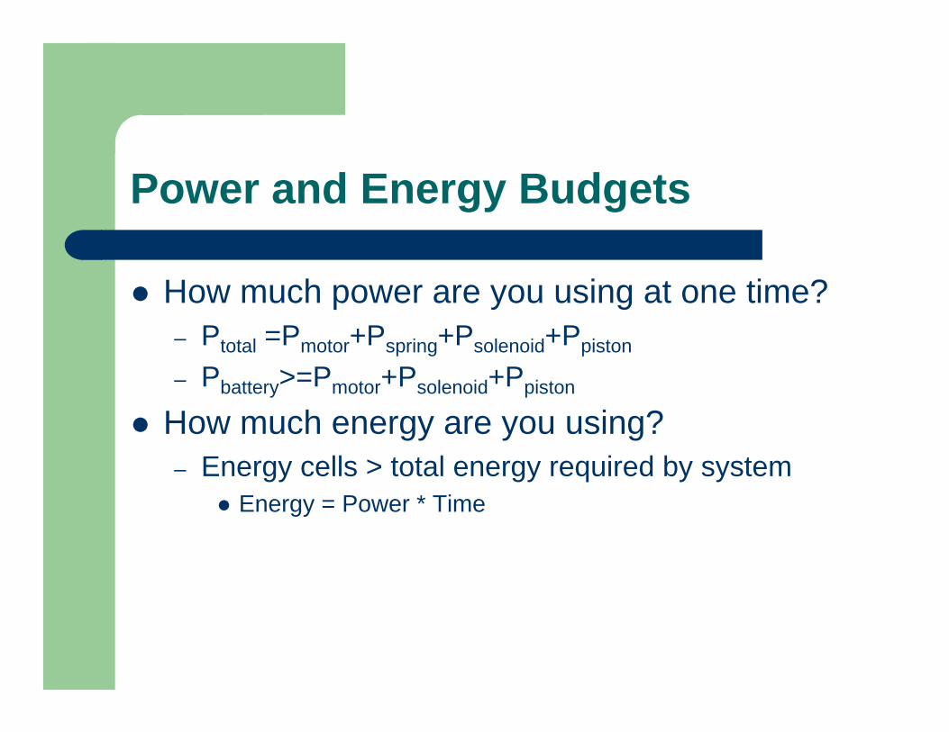
Power and Energy Budgets
How much power are you using at one time?– Ptotal =Pmotor+Pspring+Psolenoid+Ppiston
– Pbattery>=Pmotor+Psolenoid+Ppiston
How much energy are you using?– Energy cells > total energy required by system
Energy = Power * Time
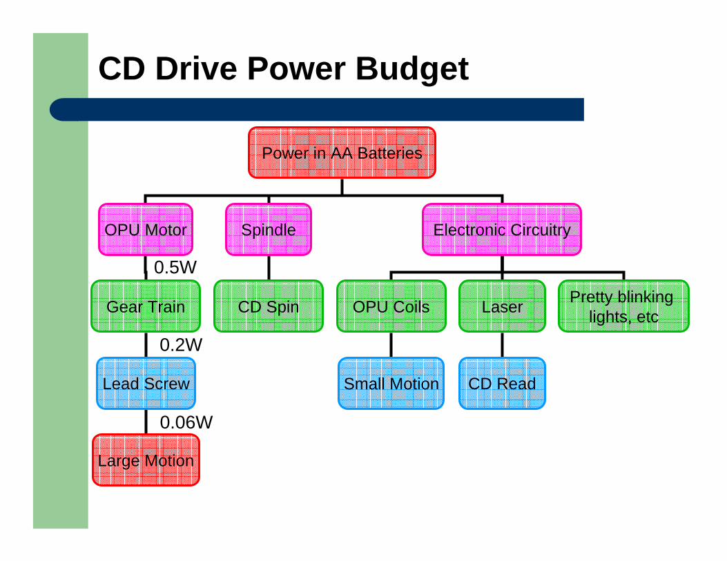
CD Drive Power Budget
Power in AA Batteries
OPU Motor Spindle Electronic Circuitry
Gear Train CD Spin OPU Coils
Lead Screw Small Motion
Large Motion
Laser
CD Read
Pretty blinking lights, etc
0.2W
0.06W
0.5W
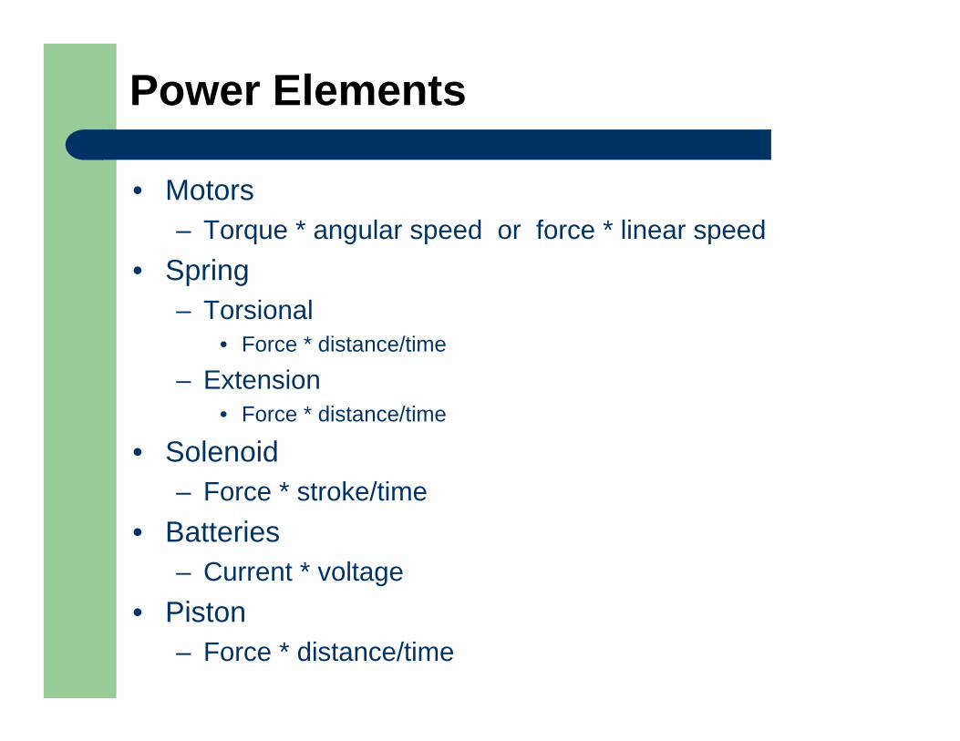
Power Elements
• Motors– Torque * angular speed or force * linear speed
• Spring– Torsional
• Force * distance/time
– Extension• Force * distance/time
• Solenoid– Force * stroke/time
• Batteries– Current * voltage
• Piston– Force * distance/time
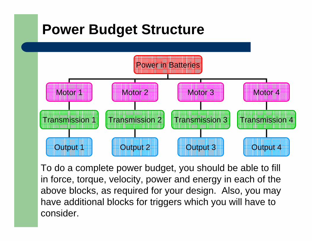
Power Budget Structure
Power in Batteries
Motor 1 Motor 2 Motor 3 Motor 4
Transmission 1 Transmission 2 Transmission 3 Transmission 4
Output 1 Output 2 Output 3 Output 4
To do a complete power budget, you should be able to fill in force, torque, velocity, power and energy in each of the above blocks, as required for your design. Also, you may have additional blocks for triggers which you will have to consider.


