16

Leading SolutionLS Mtron, LS Cable & System, LSIS,
LS-Nikko Copper, Gaon Cable, E1 and Yesco
01

Vision StatementIn order to become a leader in the competitive global market LG has been divided into three business groups based upon their core competencies, Industrial Electric-Electronic Energy & Materials(LS), Electronic & Chemical(LG), and Energy & Retail(GS).
INNOVATIVE TECHNOLOGY PARTNER - LS MtronLS Mtron’s mission is to grow into a company that provides mar-ket leading solutions while devloping a workplace where its em-ployee can achieve their dreams. All employees of LS Mtron stand behind the vision of becoming an Innovative Technology Partner and work tirelessly to make LS Mtron a world-class company
LS Mtron will secure world-class core technologies to find and im-plement the most efficient solutions based on a market knowl-edge that can meet the challanges of our today’s markets We will work hand-in-hand with our customers in order to grow into a global leader.
Business of LS Mtron
Component
Ultracapacitor
Electronic Parts Connectors / Antenna’s
Circuit Material Copper Foils / FCCL
Vehicle Parts Automotive Rubber Hose
Machinery
Tractor
Injection Molding Machine
Track Shoes
Industrial Electric·Electronic, Energy & Material
Electronic & Chemical
Energy & Retail
02

OverviewLS Ultracapacitor energy storage devices are positioned between conventional electrolytic capacitors and rechargeable batteries.LS Ultra capacitors feature high power, high energy, reliability and long life which enables use in a variety of applications such as back-up power, auxiliary power, instantaneous power compensation and peak power compensation.
· Rated voltage : up to 3.0V· High power performance (vs. Battery)· High energy performance (vs. Conventional electrolytic capacitor)· Environmentally friendly· Maintenance-free· Wide operating temperature range (-40oC ~ +65oC)
03
New-generation Energy Storage Devices with Low Resistance and Great ReliabilityLS Ultracapacitor

04
New-generation Energy Storage Devices with Low Resistance and Great Reliability
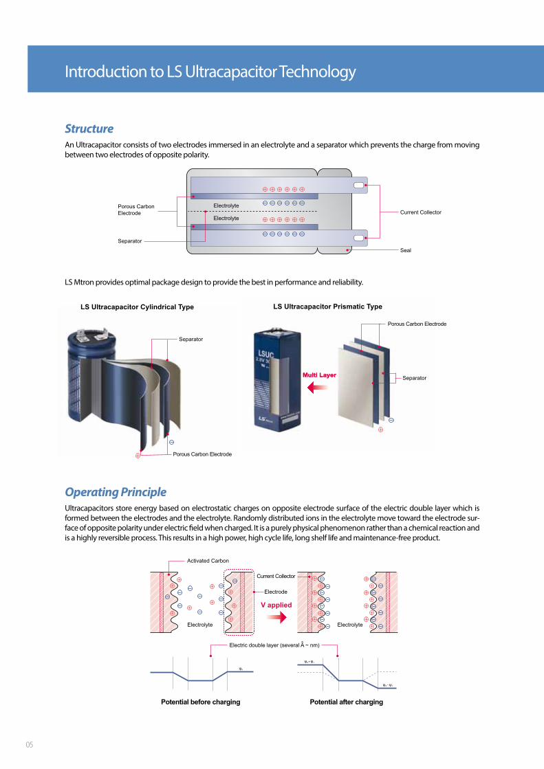
Introduction to LS Ultracapacitor Technology
Operating PrincipleUltracapacitors store energy based on electrostatic charges on opposite electrode surface of the electric double layer which is formed between the electrodes and the electrolyte. Randomly distributed ions in the electrolyte move toward the electrode sur-face of opposite polarity under electric field when charged. It is a purely physical phenomenon rather than a chemical reaction and is a highly reversible process. This results in a high power, high cycle life, long shelf life and maintenance-free product.
LS Mtron provides optimal package design to provide the best in performance and reliability.
StructureAn Ultracapacitor consists of two electrodes immersed in an electrolyte and a separator which prevents the charge from moving between two electrodes of opposite polarity.
05
Formulas for calculating energy in a capacitorThe different units used between Ultracapacitors (Farad) and batteries (Ampere hour) can be confusing to users when adoptingUltracapacitors in their system. The amount of energy stored in an Ultracapacitor can be easily calculated by using following equation.
Energy (Joule) = 1/2 x Capacitance (Farad) x Voltage2 (Volt)
This can be converted from Farad for Ultracapacitors to Watt hour unit which is normally used for conventional rechargeable batteries.
Energy (Watt hour) = Energy (Joule) / 3600 (sec)
LS Mtron recommends discharging Ultracapacitors from 100% of their rated voltage to 50% of their rated voltage in order todeliver 75% of their total energy.
Differences Between LS Ultracapacitor & Other Energy Storage Devices
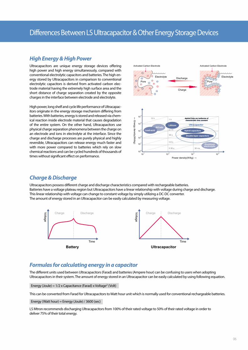
High Energy & High PowerUltracapacitors are unique energy storage devices offering high power and high energy simultaneously, compared with conventional electrolytic capacitors and batteries. The high en-ergy stored by Ultracapacitors in comparison to conventional electrolytic capacitors is derived from activated carbon elec-trode material having the extremely high surface area and the short distance of charge separation created by the opposite charges in the interface between electrode and electrolyte.
High power, long shelf and cycle life performance of Ultracapac-itors originate in the energy storage mechanism differing from batteries. With batteries, energy is stored and released via chem-ical reaction inside electrode material that causes degradation of the entire system. On the other hand, Ultracapacitors use physical charge separation phenomena between the charge on an electrode and ions in electrolyte at the interface. Since the charge and discharge processes are purely physical and highly reversible, Ultracapacitors can release energy much faster and with more power compared to batteries which rely on slow chemical reactions and can be cycled hundreds of thousands of times without significant effect on performance.
Hybrid capacitors
Charge & DischargeUltracapacitors possess different charge and discharge characteristics compared with rechargeable batteries. Batteries have a voltage plateau region but Ultracapacitors have a linear relationship with voltage during charge and discharge.This linear relationship with voltage can change to constant voltage by simply utilizing a DC-DC converter. The amount of energy stored in an Ultracapacitor can be easily calculated by measuring voltage.
06
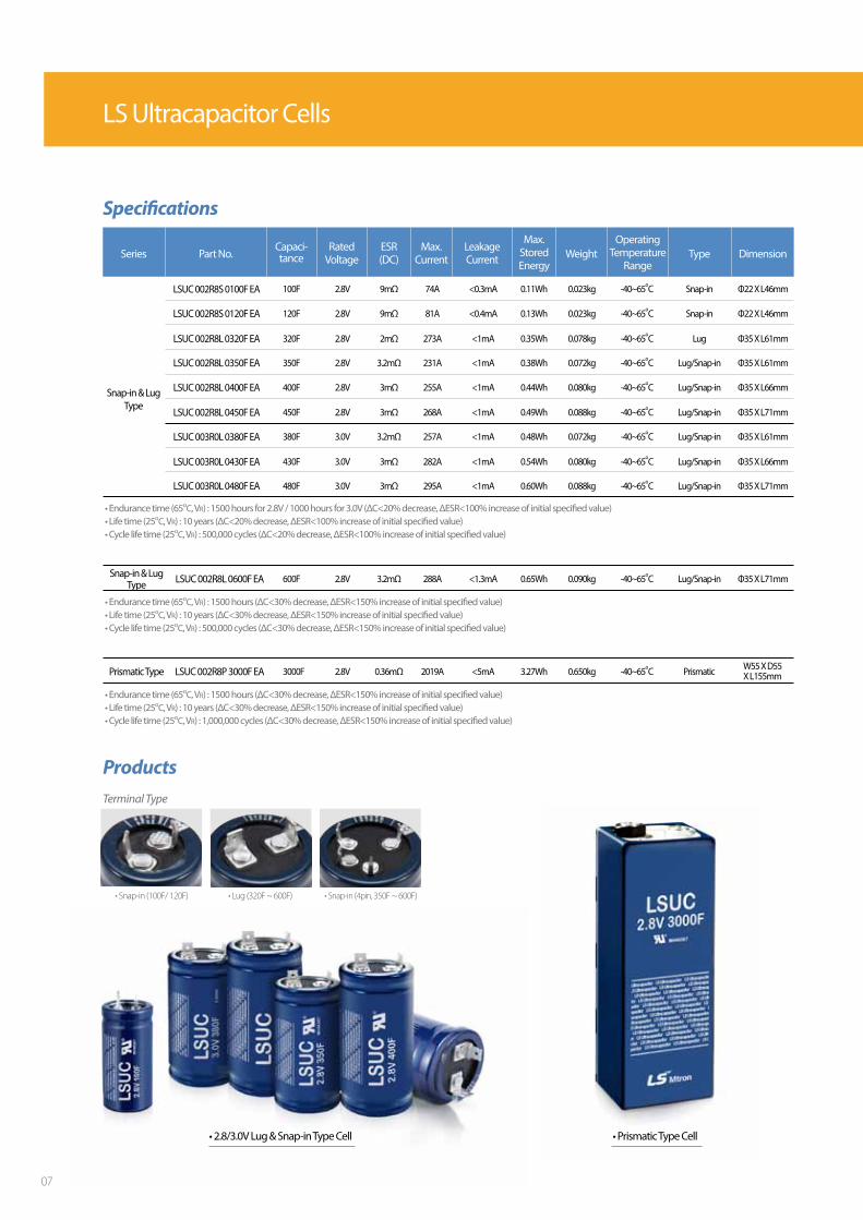
• Endurance time (65oC, VR) : 1500 hours (ΔC<30% decrease, ΔESR<150% increase of initial specified value)• Life time (25oC, VR) : 10 years (ΔC<30% decrease, ΔESR<150% increase of initial specified value)• Cycle life time (25oC, VR) : 500,000 cycles (ΔC<30% decrease, ΔESR<150% increase of initial specified value)
Snap-in & LugType LSUC 002R8L 0600F EA 600F 2.8V 3.2mΩ 288A <1.3mA 0.65Wh 0.090kg -40~65oC Lug/Snap-in Φ35 X L71mm
• Endurance time (65oC, VR) : 1500 hours (ΔC<30% decrease, ΔESR<150% increase of initial specified value)• Life time (25oC, VR) : 10 years (ΔC<30% decrease, ΔESR<150% increase of initial specified value)• Cycle life time (25oC, VR) : 1,000,000 cycles (ΔC<30% decrease, ΔESR<150% increase of initial specified value)
Prismatic Type LSUC 002R8P 3000F EA 3000F 2.8V 0.36mΩ 2019A <5mA 3.27Wh 0.650kg -40~65oC Prismatic W55 X D55 X L155mm
Products
• Prismatic Type Cell• 2.8/3.0V Lug & Snap-in Type Cell
Terminal Type
• Snap-in (100F/ 120F) • Lug (320F ~ 600F) • Snap-in (4pin, 350F ~ 600F)
LSUC 003R0L 0380F EA 380F 3.0V 3.2mΩ 257A <1mA 0.48Wh 0.072kg -40~65oC Lug/Snap-in Φ35 X L61mm
LSUC 002R8L 0320F EA 320F 2.8V 2mΩ 273A <1mA 0.35Wh 0.078kg -40~65oC Lug Φ35 X L61mm
LSUC 002R8S 0120F EA 120F 2.8V 9mΩ 81A <0.4mA 0.13Wh 0.023kg -40~65oC Snap-in Φ22 X L46mm
LSUC 003R0L 0430F EA 430F 3.0V 3mΩ 282A <1mA 0.54Wh 0.080kg -40~65oC Lug/Snap-in Φ35 X L66mm
LSUC 002R8L 0350F EA 350F 2.8V 3.2mΩ 231A <1mA 0.38Wh 0.072kg -40~65oC Lug/Snap-in Φ35 X L61mm
LSUC 003R0L 0480F EA 480F 3.0V 3mΩ 295A <1mA 0.60Wh 0.088kg -40~65oC Lug/Snap-in Φ35 X L71mm
LSUC 002R8L 0400F EA 400F 2.8V 3mΩ 255A <1mA 0.44Wh 0.080kg -40~65oC Lug/Snap-in Φ35 X L66mm
LSUC 002R8L 0450F EA 450F 2.8V 3mΩ 268A <1mA 0.49Wh 0.088kg -40~65oC Lug/Snap-in Φ35 X L71mm
Snap-in & LugType
Specifications
Series Part No.Capaci-tance Weight Type Dimension
RatedVoltage
ESR(DC)
Max. Current
LeakageCurrent
Operating Temperature
Range
Max. StoredEnergy
LSUC 002R8S 0100F EA 100F 2.8V 9mΩ 74A <0.3mA 0.11Wh 0.023kg -40~65oC Snap-in Φ22 X L46mm
• Endurance time (65oC, VR) : 1500 hours for 2.8V / 1000 hours for 3.0V (ΔC<20% decrease, ΔESR<100% increase of initial specified value)• Life time (25oC, VR) : 10 years (ΔC<20% decrease, ΔESR<100% increase of initial specified value)• Cycle life time (25oC, VR) : 500,000 cycles (ΔC<20% decrease, ΔESR<100% increase of initial specified value)
LS Ultracapacitor Cells
07
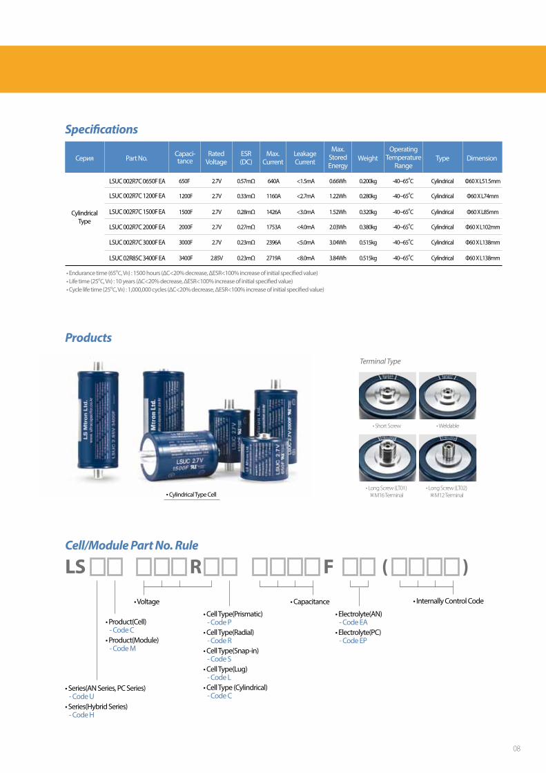
Cell/Module Part No. Rule
)LS R F (
• Series(AN Series, PC Series) - Code U • Series(Hybrid Series) - Code H
• Product(Cell) - Code C • Product(Module) - Code M
• Cell Type(Prismatic) - Code P • Cell Type(Radial) - Code R • Cell Type(Snap-in) - Code S• Cell Type(Lug) - Code L• Cell Type (Cylindrical) - Code C
• Electrolyte(AN) - Code EA • Electrolyte(PC) - Code EP
• Voltage • Capacitance • Internally Control Code
Products
• Cylindrical Type Cell
• Short Screw • Weldable
• Long Screw (LT01)※M16 Terminal
• Long Screw (LT02)※M12 Terminal
Terminal Type
• Endurance time (65oC, VR) : 1500 hours (ΔC<20% decrease, ΔESR<100% increase of initial specified value)• Life time (25oC, VR) : 10 years (ΔC<20% decrease, ΔESR<100% increase of initial specified value)• Cycle life time (25oC, VR) : 1,000,000 cycles (ΔC<20% decrease, ΔESR<100% increase of initial specified value)
Specifications
Серия Part No.Capaci-tance Weight Type Dimension
RatedVoltage
ESR(DC)
Max. Current
LeakageCurrent
Operating Temperature
Range
Max. StoredEnergy
LSUC 002R7C 3000F EA 3000F 2.7V 0.23mΩ 2396A <5.0mA 3.04Wh 0.515kg -40~65oC Cylindrical Φ60 X L138mm
LSUC 02R85C 3400F EA 3400F 2.85V 0.23mΩ 2719A <8.0mA 3.84Wh 0.515kg -40~65oC Cylindrical Φ60 X L138mm
LSUC 002R7C 1200F EA 1200F 2.7V 0.33mΩ 1160A <2.7mA 1.22Wh 0.280kg -40~65oC Cylindrical Φ60 X L74mm
LSUC 002R7C 1500F EA 1500F 2.7V 0.28mΩ 1426A <3.0mA 1.52Wh 0.320kg -40~65oC Cylindrical Φ60 X L85mm
LSUC 002R7C 2000F EA 2000F 2.7V 0.27mΩ 1753A <4.0mA 2.03Wh 0.380kg -40~65oC Cylindrical Φ60 X L102mm
CylindricalType
650F 2.7V 0.57mΩ 640A <1.5mA 0.66Wh 0.200kg -40~65oC Cylindrical Φ60 X L51.5mmLSUC 002R7C 0650F EA
08

LS Ultracapacitor Modules provide the optimal solution for high voltage and current requirements by connectingUltracapacitor unit cells in series. Higher voltage and capacitance modules can be built simply by connecting the modules.
Low internal resistance and high working voltage features of LS Mtron modules maximize the available energy while keeping maintenance free, high reliability and wide operating temperature features of LS Ultracapacitor unit cell.
Features• Low Internal Resistance • Balancing and Overvoltage Protection• Easy Build-up Design for High Voltage Module• Efficient Heat Transfer to Outside• Pressure / Moisture Control
LS Ultracapacitor modules are suitable energy storage systems for a wide variety of applications.
New-generation Energy StorageDevices with Low Resistance andGreat Reliability
LS Ultracapacitor
• Leakage Current(1) can be changed by Balancing method• NTC Thermistor & Group voltage monitoring via CAN2.0B• Customized module can be supplied under the customer`s requirement
LSUM 086R4C 0093F EA 93F 86.4V 11.3mΩ 80A <120mA 3.6Wh/kg 27kg Passive -40 ~ 65oC L517 x W265 x H210.5mm
LSUM 129R6C 0062F EA 62F 129.6V 13.2mΩ 260A <5mA 2.6Wh/kg 55kg Active or Passive -40 ~ 65oC L720 x W405 x H226mm
Temperature(PT100)
Temperature & Voltage (CAN2.0B)
Specifications
LSUM 016R8L 0058F EA 58F 16.8V 22mΩ 20A <11mA 3.2Wh/kg 0.7kg Active or Passive - -40 ~ 65oC L245 x W47 x H76.6mm
Part No. Weight Balancing Monitoring DimensionRated
VoltageESR(DC)
Max. Continuous
Current(ΔT = 40oC)
OperatingTemperature
Range
EnergyDensity
LeakageCurrent(1)
Capaci-tance
LSUM 016R2C 0500F EA
LSUM 016R2C 0500F EA AG
LSUM 016R2C 0250F EA AG
500F 16.2V 1.7mΩ 200A <5mA 3.3Wh/kg 5.6kg Active or Passive
500F 16.2V 1.7mΩ 200A <5mA 3.1Wh/kg 5.9kg Active or Passive
250F 16.2V 2mΩ 150A <3mA 2.3Wh/kg 3.9kg Active or Passive
-40 ~ 65oC L67.2 x W416.2 x H175.9mm
-40 ~ 65oC L470 x W166 x H70mm
-40 ~ 65oC L311 x W166 x H70mm
LSUM 048R6C 0166F EA DC 166F 48.6V 5mΩ 130A <5mA 3.9Wh/kg 14kg Active or Passive -40 ~ 65oC L194.5 x W419.5 x H175.4mm
Temperature(NTC)
Temperature(NTC)
Temperature(NTC)
Temperature (NTC) / Over Voltage
LSUM 032R4C 0250F EA 250F 32.4V 3.3mΩ 150A <11mA 3.6Wh/kg 10kg Passive -40 ~ 65oC L137.1 x W426.6 x H184mm-
LSUM 048R6C 0166F EA YJ 166F 48.6V 5mΩ 200A <5mA 3.2Wh/kg 17.2kg Active or Passive -40 ~ 65oC L471 x W418 x H71mmTemperature
(NTC)
LSUM 051R3C 0166F EA 166F 51.3V 5mΩ 100A <28.5mA 5.1Wh/kg 12kg Active & Passive -40 ~ 65oC L590.4 x W136 x H181mmTemperature (PTC) /
Over Voltage
LSUM 0380R8L 0002F EA 2.5F 380.8V 650mΩ 12A <12mA 2.7Wh/kg 18.4kg Passive -40 ~ 65oC L750 x W191 x H163mmTemperature (PTC) / Over Voltage
LSUM 168R0L 0005F EA 5.8F 168V 240mΩ 12A <25mA 3.5Wh/kg 6.5kg Passive -40 ~ 65oC L235 x W367 x H79mmTemperature (NTC) /Half Voltage Terminal
LS Ultracapacitor Modules
09
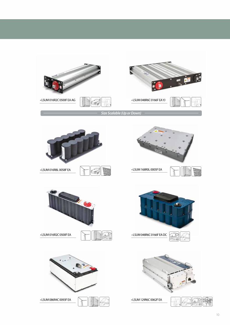
• LSUM 048R6C 0166F EA DC
• LSUM 048R6C 0166F EA YJ• LSUM 016R2C 0500F EA AG
• LSUM 086R4C 0093F EA • LSUM 129R6C 0062F EA
• LSUM 016R8L 0058F EA • LSUM 168R0L 0005F EA
• LSUM 016R2C 0500F EA
Size Scalable (Up or Down)
10
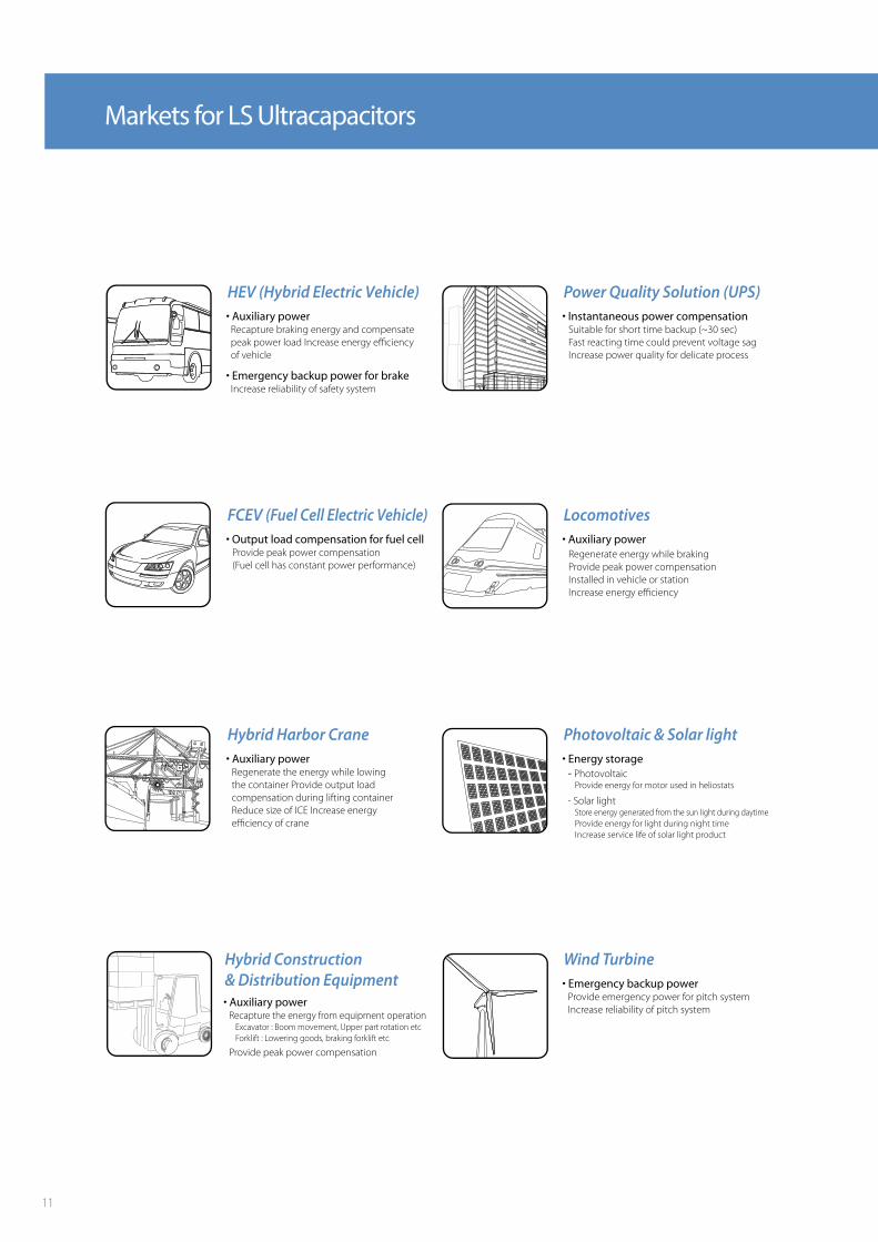
Markets for LS Ultracapacitors
HEV (Hybrid Electric Vehicle)• Auxiliary power Recapture braking energy and compensate peak power load Increase energy efficiency of vehicle
• Emergency backup power for brake Increase reliability of safety system
FCEV (Fuel Cell Electric Vehicle)• Output load compensation for fuel cell Provide peak power compensation (Fuel cell has constant power performance)
Hybrid Harbor Crane• Auxiliary power Regenerate the energy while lowing the container Provide output load compensation during lifting container Reduce size of ICE Increase energy efficiency of crane
Hybrid Construction& Distribution Equipment• Auxiliary power Recapture the energy from equipment operation Excavator : Boom movement, Upper part rotation etc Forklift : Lowering goods, braking forklift etc
Provide peak power compensation
Photovoltaic & Solar light• Energy storage - Photovoltaic Provide energy for motor used in heliostats
- Solar light Store energy generated from the sun light during daytime Provide energy for light during night time Increase service life of solar light product
Wind Turbine• Emergency backup power Provide emergency power for pitch system Increase reliability of pitch system
Power Quality Solution (UPS)• Instantaneous power compensation Suitable for short time backup (~30 sec) Fast reacting time could prevent voltage sag Increase power quality for delicate process
Locomotives• Auxiliary power Regenerate energy while braking Provide peak power compensation Installed in vehicle or station Increase energy efficiency
11

12

Atlanta Branch Office
LS Mtron
39, 116beon-gil, LS-ro, Dongan-gu, Anyang-si,Gyeonggi-do, 14118, Korea
9579
13

Atlanta Branch Office
LS Mtron
39, 116beon-gil, LS-ro, Dongan-gu, Anyang-si,Gyeonggi-do, 14118, Korea
9579
14


