This symbol mark is for EU countries only. This symbol mark is according to the directive 2002/96/EC Article 10 Information for users and Annex IV. This product is designed and manufactured with high quality materials and components which can be recycled and reused. This symbol means that electrical and electronic equipment, at the end-of-life, should be disposed of separately from your household waste. Please dispose of this equipment at your local community waste collection / recycling centre. In the European Union there are separate collection systems for used electrical and electronic product.
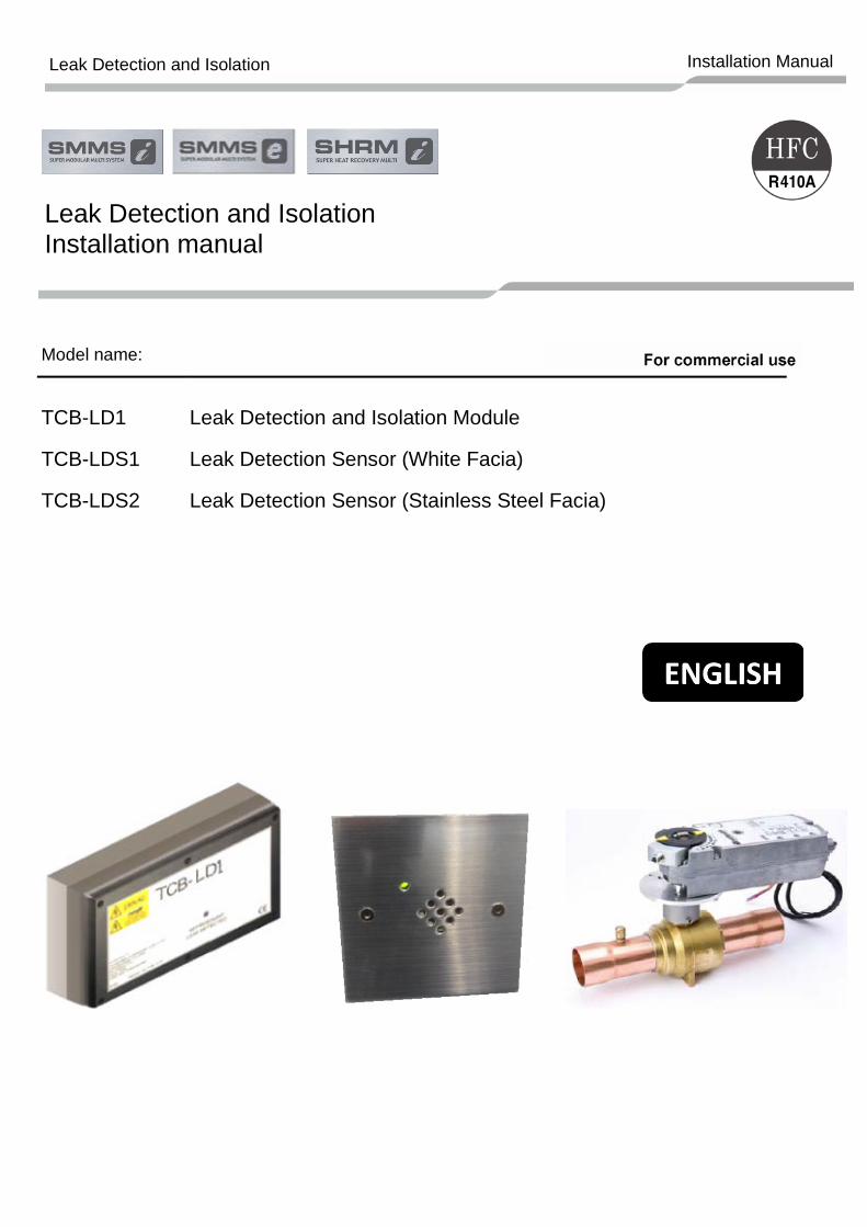
Please read this Installation Manual carefully before installing any of the Leak Detection products. • This manual describes the installation method of the LD1 isolation control module, including
the isolation valves and the LDS1 and LDS2 Leak Detection sensors. • You must also refer to the Installation and Owner’s Manual attached to the Toshiba outdoor unit. • Toshiba does not take any responsibility on the local design.
ADOPTION OF NEW REFRIGERANT
This Air Conditioner is a new type which adopts a new refrigerant HFC (R410A) instead of the conventional refrigerant R22 in order to prevent destruction of the ozone layer. This appliance is for commercial use only and should not be accessible to the general public. This appliance is not intended for use by person (including children) with reduced physical, sensory or mental capabilities, or lack of experience and knowledge, unless they have been given supervision or instruction concerning use of the appliance by a person responsible for their safety. Children should be supervised to ensure that they do not play with the appliance. Contents 1 PRODUCT OVERVIEW: LEAK DETECTION AND ISOLATION . . . . . . . . . . . . . . 6
Thank you for purchasing Toshiba air conditioning products. Please read carefully through these instructions, as they contain important information and ensure that you fully understand them. After completing the installation work, hand over this installation manual, as well as the owner’s manual attached to the outdoor unit to the user and ask the user to keep them in a safe place for future reference. Generic Denomination: Refrigerant Leak Detection System Definition of Qualified Installer or Qualified Service Person The refrigerant leak detection system must be installed, maintained, repaired and removed by a qualified installer or qualified service person. When any of these jobs is to be done, ask a qualified installer or qualified service person to do them for you. A qualified installer or qualified service person is an agent who has the qualifications and knowledge described in the table below. Agent Qualifications and knowledge which the agent must have
Qualified Installer
• The qualified installer is a person who installs, maintains, relocates and removes the air conditioners made by the OEM manufacture. He or she has been trained to install, maintain, relocate and remove the air conditioners made by the OEM manufacture or, alternatively, he or she has been instructed in such operations by an individual or individuals who have been trained and is thus thoroughly acquainted with the knowledge related to these operations.
• The qualified installer who is allowed to do the electrical work involved in installation, relocation and removal has the qualifications pertaining to this electrical work as stipulated by the local laws and regulations, and he or she is a person who has been trained in matters relating to electrical work on the air conditioners made by the OEM manufacture or, alternatively, he or she has been instructed in such matters by an individual or individuals who have been trained and is thus thoroughly acquainted with the knowledge related to this work.
• The qualified installer who is allowed to do the refrigerant handling and piping work involved in installation, relocation and removal has the qualifications pertaining to this refrigerant handling and piping work as stipulated by the local laws and regulations, and he or she is a person who has been trained in matters relating to refrigerant handling and piping work on the air conditioners made by the OEM manufacture or, alternatively, he or she has been instructed in such matters by an individual or individuals who have been trained and is thus thoroughly acquainted with the knowledge related to this work.
• The qualified installer who is allowed to work at heights has been trained in matters relating to working at heights with the air conditioners made by the OEM manufacture or, alternatively, he or she has been instructed in such matters by an individual or individuals who have been trained and is thus thoroughly acquainted with the knowledge related to this work.
4
Leak Detection and Isolation Installation Manual
Qualified Service Person
• The qualified service person is a person who installs, repairs, maintains, relocates and removes the air conditioners made by the OEM manufacture. He or she has been trained to install, repair, maintain, relocate and remove the air conditioners made by the OEM manufacture or, alternatively, he or she has been instructed in such operations by an individual or individuals who have been trained and is thus thoroughly acquainted with the knowledge related to these operations.
• The qualified service person who is allowed to do the electrical work involved in installation, repair, relocation and removal has the qualifications pertaining to this electrical work as stipulated by the local laws and regulations, and he or she is a person who has been trained in matters relating to electrical work on the air conditioners made by the OEM manufacture or, alternatively, he or she has been instructed in such matters by an individual or individuals who have been trained and is thus thoroughly acquainted with the knowledge related to this work.
• The qualified service person who is allowed to do the refrigerant handling and piping work involved in installation, repair, relocation and removal has the qualifications pertaining to this refrigerant handling and piping work as stipulated by the local laws and regulations, and he or she is a person who has been trained in matters relating to refrigerant handling and piping work on the air conditioners made by the OEM manufacture or, alternatively, he or she has been instructed in such matters by an individual or individuals who have been trained and is thus thoroughly acquainted with the knowledge related to this work.
• The qualified service person who is allowed to work at heights has been trained in matters relating to working at heights with the air conditioners made by the OEM manufacture or, alternatively, he or she has been instructed in such matters by an individual or individuals who have been trained and is thus thoroughly acquainted with the knowledge related to this work.
Definition of Protective Gear When the air conditioner is to be transported, installed, maintained, repaired or removed, wear protective gloves and ‘safety’ work clothing. In addition to such normal protective gear, wear the protective gear described below when undertaking the special work detailed in the table below. Failure to wear the proper protective gear is dangerous because you will be more susceptible to injury, burns, electric shocks and other injuries.
Work undertaken Protective gear worn
All types of work Protective gloves ‘Safety’ working clothing
Electrical-related work Gloves to provide protection for electricians and from heat, Insulating shoes and Clothing to provide protection from electric shock
Work done at heights (50 cm or more) Helmets for use in industry
Transportation of heavy objects Shoes with additional protective toe cap
Repair of outdoor unit Gloves to provide protection for electricians and from heat
5
Leak Detection and Isolation Installation Manual
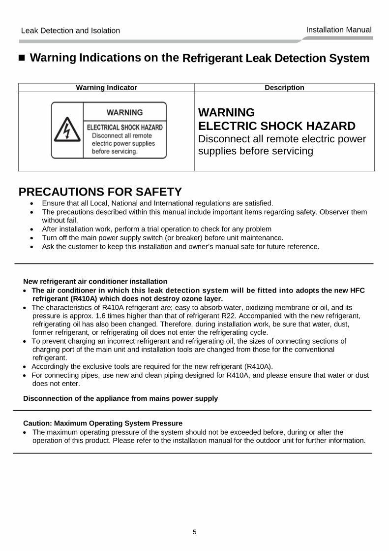
Warning Indications on the Refrigerant Leak Detection System
Warning Indicator Description
WARNING ELECTRIC SHOCK HAZARD Disconnect all remote electric power supplies before servicing
PRECAUTIONS FOR SAFETY
• Ensure that all Local, National and International regulations are satisfied. • The precautions described within this manual include important items regarding safety. Observer them
without fail. • After installation work, perform a trial operation to check for any problem • Turn off the main power supply switch (or breaker) before unit maintenance. • Ask the customer to keep this installation and owner’s manual safe for future reference.
New refrigerant air conditioner installation • The air conditioner in which this leak detection system will be fitted into adopts the new HFC
refrigerant (R410A) which does not destroy ozone layer. • The characteristics of R410A refrigerant are; easy to absorb water, oxidizing membrane or oil, and its
pressure is approx. 1.6 times higher than that of refrigerant R22. Accompanied with the new refrigerant, refrigerating oil has also been changed. Therefore, during installation work, be sure that water, dust, former refrigerant, or refrigerating oil does not enter the refrigerating cycle.
• To prevent charging an incorrect refrigerant and refrigerating oil, the sizes of connecting sections of charging port of the main unit and installation tools are changed from those for the conventional refrigerant.
• Accordingly the exclusive tools are required for the new refrigerant (R410A). • For connecting pipes, use new and clean piping designed for R410A, and please ensure that water or dust
does not enter.
Disconnection of the appliance from mains power supply Caution: Maximum Operating System Pressure • The maximum operating pressure of the system should not be exceeded before, during or after the
operation of this product. Please refer to the installation manual for the outdoor unit for further information.
6
Leak Detection and Isolation Installation Manual
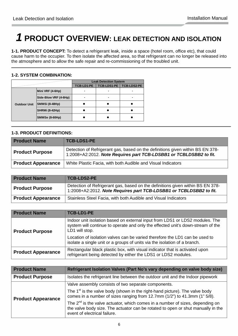
1 PRODUCT OVERVIEW: LEAK DETECTION AND ISOLATION 1-1. PRODUCT CONCEPT: To detect a refrigerant leak, inside a space (hotel room, office etc), that could cause harm to the occupier. To then isolate the affected area, so that refrigerant can no longer be released into the atmosphere and to allow the safe repair and re-commissioning of the troubled unit. 1-2. SYSTEM COMBINATION:
1-3. PRODUCT DEFINITIONS:
Product Name TCB-LDS1-PE
Product Purpose Detection of Refrigerant gas, based on the definitions given within BS EN 378-1:2008+A2:2012. Note Requires part TCB-LDSBB1 or TCBLDSBB2 to fit.
Product Appearance White Plastic Facia, with both Audible and Visual Indicators
Product Name TCB-LDS2-PE
Product Purpose Detection of Refrigerant gas, based on the definitions given within BS EN 378-1:2008+A2:2012. Note Requires part TCB-LDSBB1 or TCBLDSBB2 to fit.
Product Appearance Stainless Steel Facia, with both Audible and Visual Indicators
Product Name TCB-LD1-PE
Product Purpose
Indoor unit isolation based on external input from LDS1 or LDS2 modules. The system will continue to operate and only the effected unit’s down-stream of the LD1 will stop. Location of isolation valves can be varied therefore the LD1 can be used to isolate a single unit or a groups of units via the isolation of a branch.
Product Appearance Rectangular black plastic box, with visual indicator that is activated upon refrigerant being detected by either the LDS1 or LDS2 modules.
Product Name Refrigerant Isolation Valves (Part No’s vary depending on valve body size)
Product Purpose Isolates the refrigerant line between the outdoor unit and the Indoor pipework
Product Appearance
Valve assembly consists of two separate components. The 1st is the valve body (shown in the right-hand picture). The valve body comes in a number of sizes ranging from 12.7mm (1/2”) to 41.3mm (1” 5/8). The 2nd is the valve actuator, which comes in a number of sizes, depending on the valve body size. The actuator can be rotated to open or shut manually in the event of electrical failure.
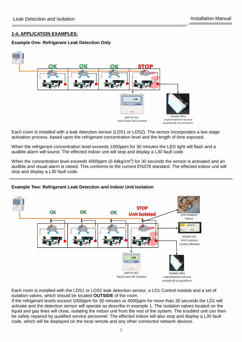
Each room is installed with a leak detection sensor (LDS1 or LDS2). The sensor incorporates a two stage activation process, based upon the refrigerant concentration level and the length of time exposed.
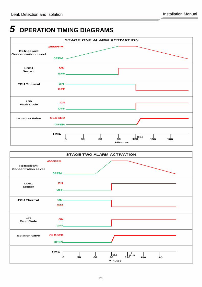
When the refrigerant concentration level exceeds 1000ppm for 30 minutes the LED light will flash and a audible alarm will sound. The effected indoor unit will stop and display a L30 fault code.
When the concentration level exceeds 4000ppm (0.44kg/cm3) for 30 seconds the sensor is activated and an audible and visual alarm is raised. This conforms to the current EN378 standard. The effected indoor unit will stop and display a L30 fault code. Example Two: Refrigerant Leak Detection and Indoor Unit Isolation
Each room is installed with the LDS1 or LDS2 leak detection sensor, a LD1 Control module and a set of isolation valves, which should be located OUTSIDE of the room. If the refrigerant levels exceed 1000ppm for 30 minutes or 4000ppm for more than 30 seconds the LD1 will activate and the detection sensor will operate as describe in example 1. The isolation valves located on the liquid and gas lines will close, isolating the indoor unit from the rest of the system. The troubled unit can then be safely repaired by qualified service personnel. The effected indoor will also stop and display a L30 fault code, which will be displayed on the local remote and any other connected network devices.
8
Leak Detection and Isolation Installation Manual
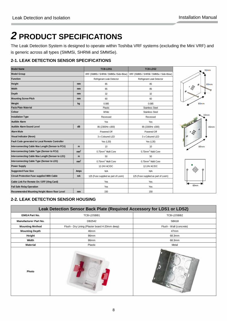
2 PRODUCT SPECIFICATIONS
The Leak Detection System is designed to operate within Toshiba VRF systems (excluding the Mini VRF) and is generic across all types (SMMSi, SHRMi and SMMSe).
Interconnecting Cable Max Length (Sensor to FCU) m 10 10
Interconnecting Cable Type (Sensor to FCU) mm2 0.75mm2 Multi Core 0.75mm2 Multi Core
Interconnecting Cable Max Length (Sensor to LD1) m 50 50
Interconnecting Cable Type (Sensor to LD1) mm2 0.75mm2 Multi Core 0.75mm2 Multi Core
12-24V AC/DC 12-24V AC/DC
Suggested Fuse Size Amps N/A N/A
Circuit Protection Fuse supplied With Cable mA 125 (Fuse supplied as part of Loom) 125 (Fuse supplied as part of Loom)
Yes Yes
Yes Yes
Recommended Mounting Height Above floor Level mm 150 150
Cable Link For Remote On / OFF (Ving Card)
Fail Safe Relay Operation
Installation Type
Audible Alarm
Alarm Mute
Visual Indicator (Neon)
Fault Code generated to Local Remote Controller
Power Supply
Colour
Model Name
Model Group
Function
Facia Plate Material
60mm
EMEA Part No.
Manufacturer Part No.
Mounting MethodMounting Depth
HeightWidth
Material
Photo
TCB-LDSBB1
Leak Detection Sensor Back Plate (Required Accessory for LDS1 or LDS2)
68.3mm
68.3mm
Metal
86mm
86mm
Plastic
TCB-LDSBB2
DB2542 SB618
Flush - Wall (concrete)
47mm
Flush - Dry Lining (Plaster board 4-20mm deep)
46mm
9
Leak Detection and Isolation Installation Manual
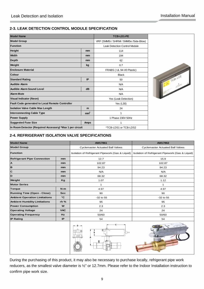
2-3. LEAK DETECTION CONTROL MODULE SPECIFICATION
2-4. REFRIGERANT ISOLATION VALVE SPECIFICATIONS
During the purchasing of this product, it may also be necessary to purchase locally, refrigerant pipe work reducers, as the smallest valve diameter is ½” or 12.7mm. Please refer to the Indoor Installation instruction to confirm pipe work size.
TCB-LD1-PE
VRF (SMMSi / SHRMi / SMMSe /Side-Blow)
Leak Detection Control Module
Height mm 114
Width mm 194
Depth mm 62
Weight kg 0.7
FRABS ( UL 94-V0 Plastic)
Black
Standard Rating IP 50
N/A
Audible Alarm Sound Level dB N/A
N/A
Yes (Leak Detection)
Yes (L30)
Isolation Valve Cable Max Length m 24
Interconnecting Cable Type mm2 1
1 Phase 230V 50Hz
Suggested Fuse Size Amps 1
*TCB-LDS1 or TCB-LDS2
Alarm Mute
Visual Indicator (Neon)
Fault Code generated to Local Remote Controller
Power Supply
In Room Detector (Required Accessory) *Max 1 per circuit
Isolation of Refrigerant Pipework (Gas & Liquid) Isolation of Refrigerant Pipework (Gas & Liquid)
Refrigerant Pipe Connection mm 12.7 15.9
A mm 102.87 102.87
B mm 94.23 94.23
C mm N/A N/A
D mm 68.32 68.32
Weight Kg 1.07 1.12
1 1
Torque N-m 4.97 4.97
Running Time (Open - Close) Sec 90 90
Ambient Operation Limitations °C -32 to 55 -32 to 55
Ambient Humidity Limitations rh % 95 95
Power Consumption W 2.3 2.3
Operating Voltage VAC 24 24
Operating Frequency Hz 50/60 50/60
IP Rating IP 54 54
Model Name
Model Group
Function
Motor Series
10
Leak Detection and Isolation Installation Manual
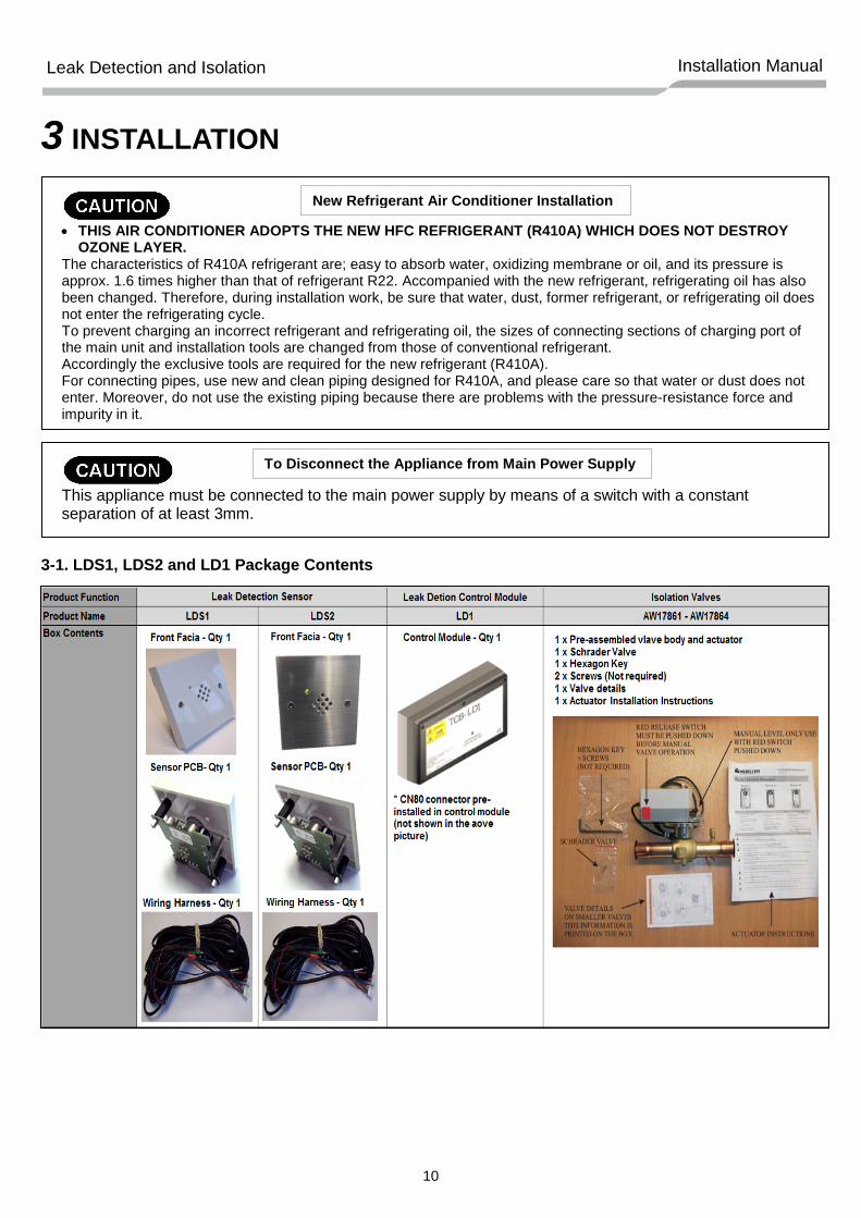
3 INSTALLATION
• THIS AIR CONDITIONER ADOPTS THE NEW HFC REFRIGERANT (R410A) WHICH DOES NOT DESTROY
OZONE LAYER. The characteristics of R410A refrigerant are; easy to absorb water, oxidizing membrane or oil, and its pressure is approx. 1.6 times higher than that of refrigerant R22. Accompanied with the new refrigerant, refrigerating oil has also been changed. Therefore, during installation work, be sure that water, dust, former refrigerant, or refrigerating oil does not enter the refrigerating cycle. To prevent charging an incorrect refrigerant and refrigerating oil, the sizes of connecting sections of charging port of the main unit and installation tools are changed from those of conventional refrigerant. Accordingly the exclusive tools are required for the new refrigerant (R410A). For connecting pipes, use new and clean piping designed for R410A, and please care so that water or dust does not enter. Moreover, do not use the existing piping because there are problems with the pressure-resistance force and impurity in it.
This appliance must be connected to the main power supply by means of a switch with a constant separation of at least 3mm.
3-1. LDS1, LDS2 and LD1 Package Contents
New Refrigerant Air Conditioner Installation
To Disconnect the Appliance from Main Power Supply
11
Leak Detection and Isolation Installation Manual
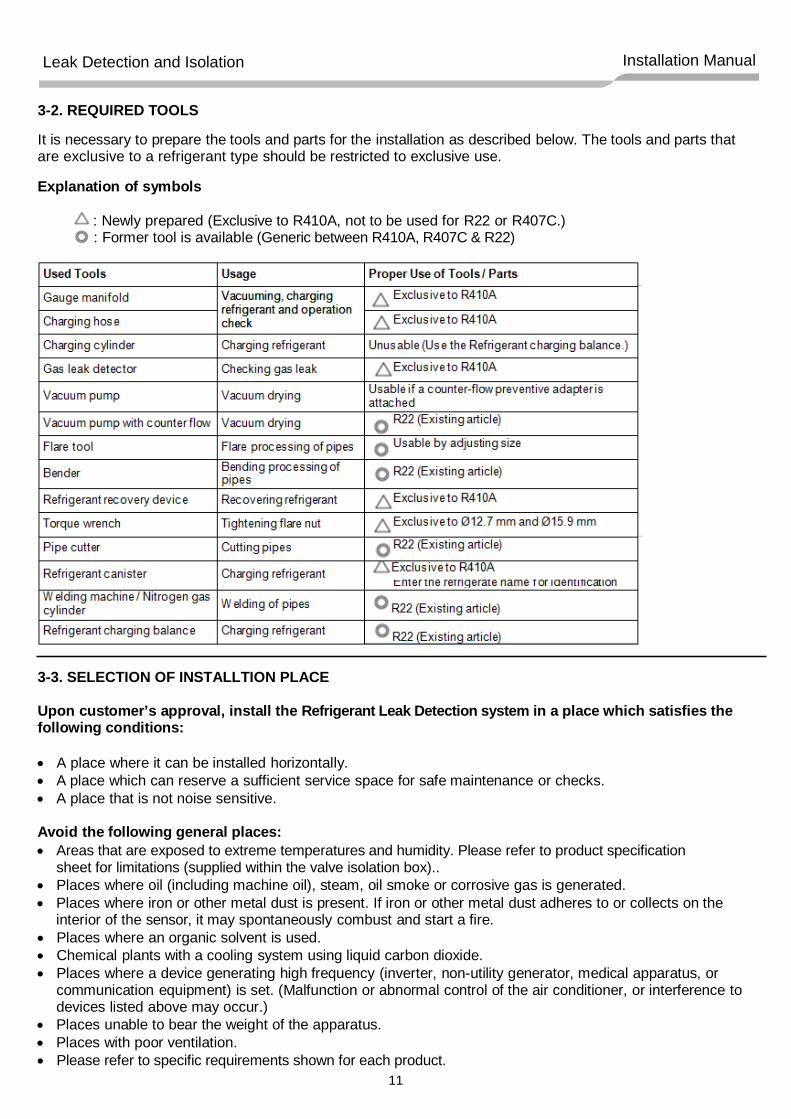
3-2. REQUIRED TOOLS
It is necessary to prepare the tools and parts for the installation as described below. The tools and parts that are exclusive to a refrigerant type should be restricted to exclusive use. Explanation of symbols
: Newly prepared (Exclusive to R410A, not to be used for R22 or R407C.) : Former tool is available (Generic between R410A, R407C & R22)
3-3. SELECTION OF INSTALLTION PLACE Upon customer’s approval, install the Refrigerant Leak Detection system in a place which satisfies the following conditions: • A place where it can be installed horizontally. • A place which can reserve a sufficient service space for safe maintenance or checks. • A place that is not noise sensitive. Avoid the following general places: • Areas that are exposed to extreme temperatures and humidity. Please refer to product specification
sheet for limitations (supplied within the valve isolation box).. • Places where oil (including machine oil), steam, oil smoke or corrosive gas is generated. • Places where iron or other metal dust is present. If iron or other metal dust adheres to or collects on the
interior of the sensor, it may spontaneously combust and start a fire. • Places where an organic solvent is used. • Chemical plants with a cooling system using liquid carbon dioxide. • Places where a device generating high frequency (inverter, non-utility generator, medical apparatus, or
communication equipment) is set. (Malfunction or abnormal control of the air conditioner, or interference to devices listed above may occur.)
• Places unable to bear the weight of the apparatus. • Places with poor ventilation. • Please refer to specific requirements shown for each product.
12
Leak Detection and Isolation Installation Manual
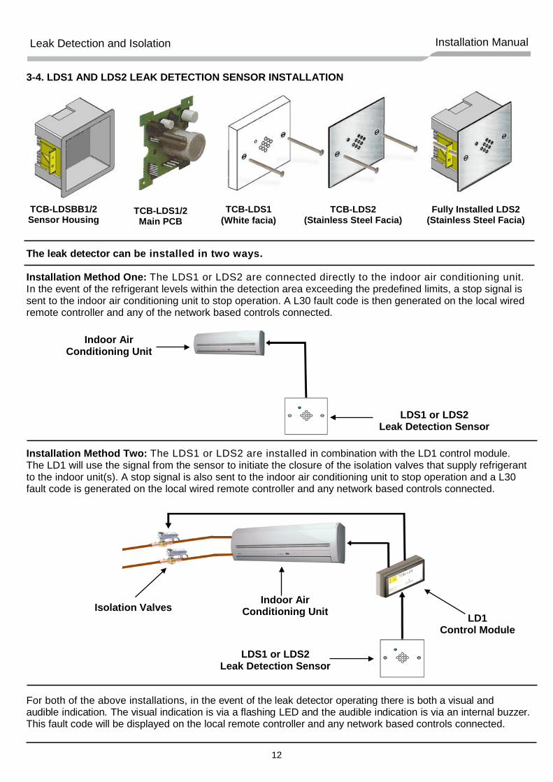
3-4. LDS1 AND LDS2 LEAK DETECTION SENSOR INSTALLATION
The leak detector can be installed in two ways. Installation Method One: The LDS1 or LDS2 are connected directly to the indoor air conditioning unit. In the event of the refrigerant levels within the detection area exceeding the predefined limits, a stop signal is sent to the indoor air conditioning unit to stop operation. A L30 fault code is then generated on the local wired remote controller and any of the network based controls connected. Installation Method Two: The LDS1 or LDS2 are installed in combination with the LD1 control module. The LD1 will use the signal from the sensor to initiate the closure of the isolation valves that supply refrigerant to the indoor unit(s). A stop signal is also sent to the indoor air conditioning unit to stop operation and a L30 fault code is generated on the local wired remote controller and any network based controls connected. For both of the above installations, in the event of the leak detector operating there is both a visual and audible indication. The visual indication is via a flashing LED and the audible indication is via an internal buzzer. This fault code will be displayed on the local remote controller and any network based controls connected.
TCB-LDS1/2 Main PCB
TCB-LDS1 (White facia)
TCB-LDS2 (Stainless Steel Facia)
TCB-LDSBB1/2 Sensor Housing
Fully Installed LDS2 (Stainless Steel Facia)
Indoor Air Conditioning Unit
LDS1 or LDS2 Leak Detection Sensor
LDS1 or LDS2 Leak Detection Sensor
LD1 Control Module
Indoor Air Conditioning Unit Isolation Valves
13
Leak Detection and Isolation Installation Manual
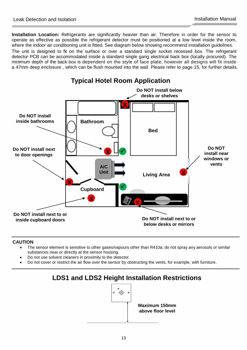
Typical Hotel Room Application
LDS1 and LDS2 Height Installation Restrictions
Installation Location: Refrigerants are significantly heavier than air. Therefore in order for the sensor to operate as effective as possible the refrigerant detector must be positioned at a low level inside the room, where the indoor air conditioning unit is fitted. See diagram below showing recommend installation guidelines. The unit is designed to fit on the surface or over a standard single socket recessed box. The refrigerant detector PCB can be accommodated inside a standard single gang electrical back box (locally procured). The minimum depth of the back box is dependent on the style of face plate, however all designs will fit inside a 47mm deep enclosure , which can be flush mounted into the wall. Please refer to page 15, for further details.
CAUTION • The sensor element is sensitive to other gases/vapours other than R410a; do not spray any aerosols or similar
substances near or directly at the sensor housing. • Do not use solvent cleaners in proximity to the detector. • Do not cover or restrict the air flow over the sensor by obstructing the vents, for example, with furniture.
A/C Unit
Do NOT install below desks or shelves
Do NOT install near windows or
vents
Do NOT install inside bathrooms
Do NOT install next to door openings
Do NOT install next to or inside cupboard doors Do NOT install next to or
below desks or mirrors
Maximum 150mm above floor level
Bed
Bathroom
Cupboard
Living Area
14
Leak Detection and Isolation Installation Manual
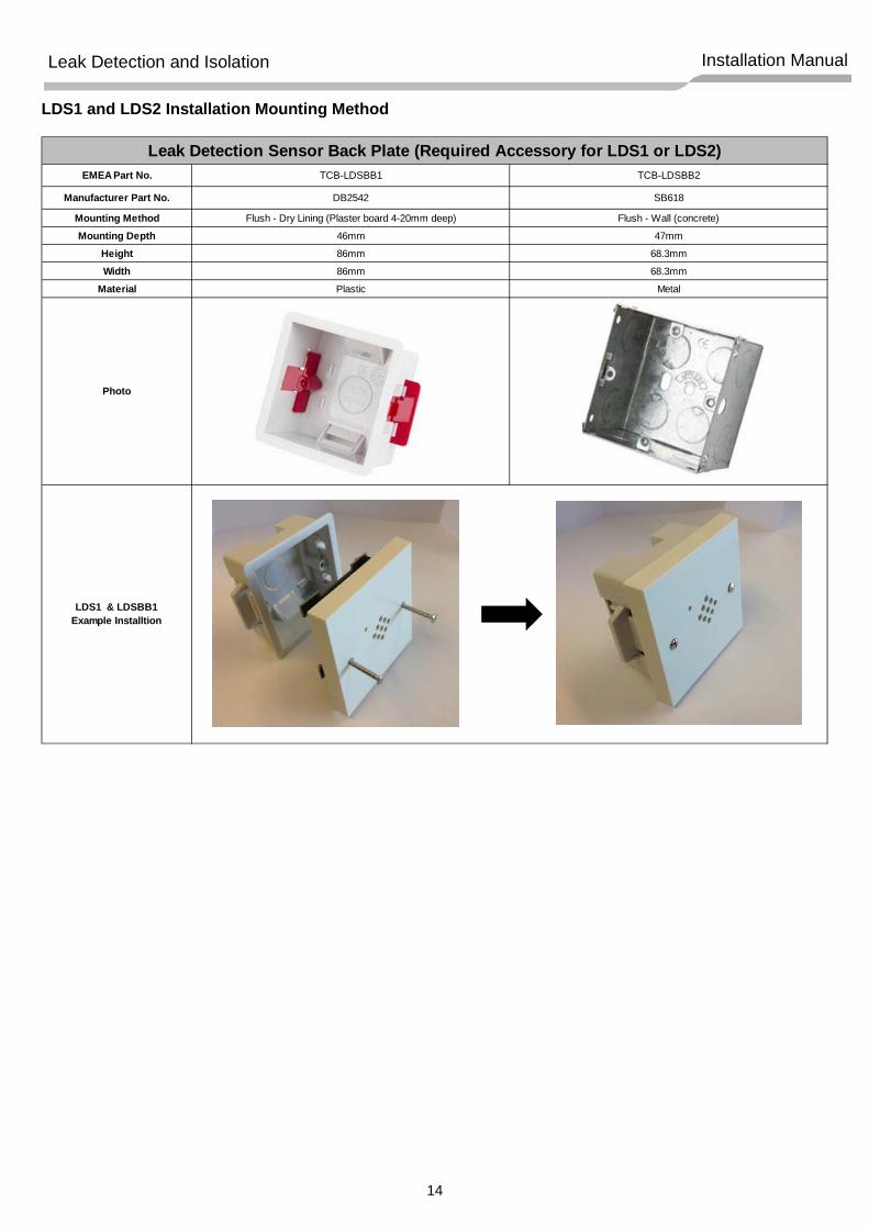
LDS1 and LDS2 Installation Mounting Method
EMEA Part No.
Manufacturer Part No.
Mounting MethodMounting Depth
HeightWidth
Material
Photo
46mm
TCB-LDSBB1
LDS1 & LDSBB1Example Installtion
Leak Detection Sensor Back Plate (Required Accessory for LDS1 or LDS2)
68.3mm
68.3mm
Metal
86mm
86mm
Plastic
TCB-LDSBB2
DB2542 SB618
Flush - Wall (concrete)
47mm
Flush - Dry Lining (Plaster board 4-20mm deep)
15
Leak Detection and Isolation Installation Manual
3-5. ISOLATION VALVE INSTALLATION SUMMARY
• The isolating valves are to be fitted in accordance with the instructions supplied with them. • Ensure the valves are located inside the building • Do not install within the protected refrigerant detection area. • Do not install inside an area that is noise sensitive. • Connect the isolation valve wiring to the dedicated terminals within the LD1 control panel, as detailed
within this installation manual. • Where indoor pipework diameter is smaller than the valve pipe diameter, a reducer should be used
(locally procured).
WARNING
• DO NOT OPEN THE ACTUATOR. IF THE ACTUATOR IS INOPERATIVE, REPLACE THE UNIT. • Do not wire different types of actuators in parallel with these models. • Personal injury/loss of life may occur if a procedure is not performed as specified. • Equipment damage or loss of data may occur if the user does not follow a procedure as specified. • To avoid injury or loss of life, pay attention to any hazardous voltage when performing checks.
IMPORTANT - Before commencing brazing of valve and pipe connection joints the valve must be in the “Open” position. Failure to manually open the valve may result in damage to internal components and malfunction in operation.
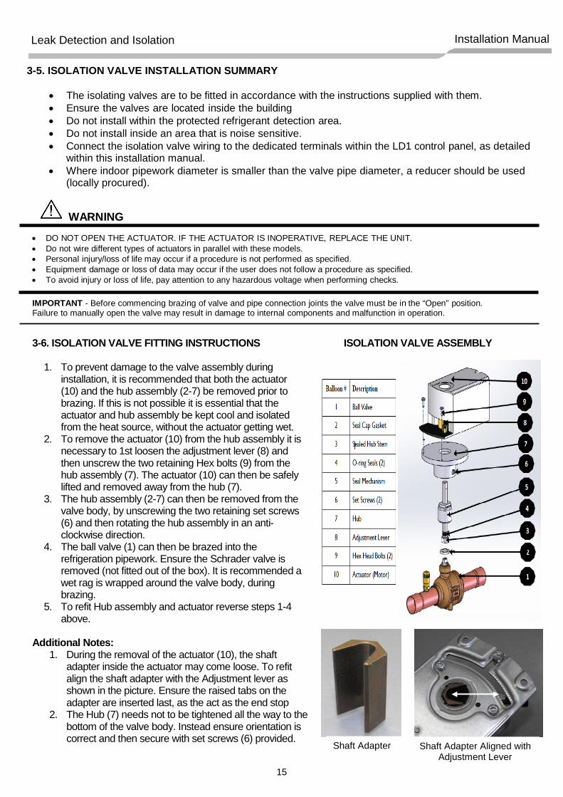
1. To prevent damage to the valve assembly during installation, it is recommended that both the actuator (10) and the hub assembly (2-7) be removed prior to brazing. If this is not possible it is essential that the actuator and hub assembly be kept cool and isolated from the heat source, without the actuator getting wet.
2. To remove the actuator (10) from the hub assembly it is necessary to 1st loosen the adjustment lever (8) and then unscrew the two retaining Hex bolts (9) from the hub assembly (7). The actuator (10) can then be safely lifted and removed away from the hub (7).
3. The hub assembly (2-7) can then be removed from the valve body, by unscrewing the two retaining set screws (6) and then rotating the hub assembly in an anti-clockwise direction.
4. The ball valve (1) can then be brazed into the refrigeration pipework. Ensure the Schrader valve is removed (not fitted out of the box). It is recommended a wet rag is wrapped around the valve body, during brazing.
5. To refit Hub assembly and actuator reverse steps 1-4 above.
Additional Notes:
1. During the removal of the actuator (10), the shaft adapter inside the actuator may come loose. To refit align the shaft adapter with the Adjustment lever as shown in the picture. Ensure the raised tabs on the adapter are inserted last, as the act as the end stop
2. The Hub (7) needs not to be tightened all the way to the bottom of the valve body. Instead ensure orientation is correct and then secure with set screws (6) provided.
Shaft Adapter Shaft Adapter Aligned with Adjustment Lever
16
Leak Detection and Isolation Installation Manual
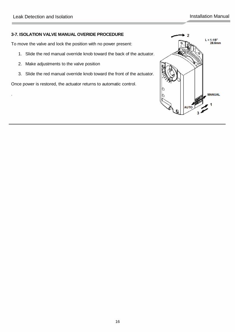
3-7. ISOLATION VALVE MANUAL OVERIDE PROCEDURE To move the valve and lock the position with no power present:
1. Slide the red manual override knob toward the back of the actuator.
2. Make adjustments to the valve position
3. Slide the red manual override knob toward the front of the actuator. Once power is restored, the actuator returns to automatic control.
.
17
Leak Detection and Isolation Installation Manual
4 ELECTRICAL WORK
WARNING
1. Using the specified wires, ensure to connect the wires, and fix wires securely so that the external tension to the wires do not affect the connecting part of the terminals.
Incomplete connection or fixation may cause a fire, etc.
2. Be sure to connect earth wire (grounding work).
Incomplete grounding cause an electric shock. Do not connect ground wires to gas pipes, water
pipes, lightning rods or ground wires for telephone wires.
3. Appliance shall be installed in accordance with national wiring regulations.
Capacity shortage of power circuit or incomplete installation may cause an electric shock or a fire.
CAUTION • If incorrect / incomplete wiring is carried out, it will
cause an electrical fire or smoke. • Be sure to install an earth leakage breaker that is
not tripped by shock waves. If an earth leakage breaker is not installed, an electric shock may be caused.
• Be sure to use the cord clamps attached to the product.
• Do not damage or scratch the conductive core and inner insulator of power and inter-connecting wires when peeling them.
• Use the power cord and inter-connecting wire of specified thickness, type and protective devices required
• Never connect 220-240V power to the terminal blocks ( , etc) for control wiring (otherwise the system will fail).
REQUIREMENT
• For power supply wiring, strictly conform to the
Local Regulation for each country. • For wiring of power supply of the outdoor units,
follow the Installation manual of each outdoor unit.
• Perform the electric wiring so that it does not come in to contact with the high-temperature part of the pipe. The coating may melt in an accident
• After connecting wires to the terminal blocks, provide a trap and fix the wires with the cord clamp.
• Run the refrigerant piping and control wiring line in the same line.
• Do not turn on the power of the indoor unit until vacuuming of the refrigerant pipes completes.
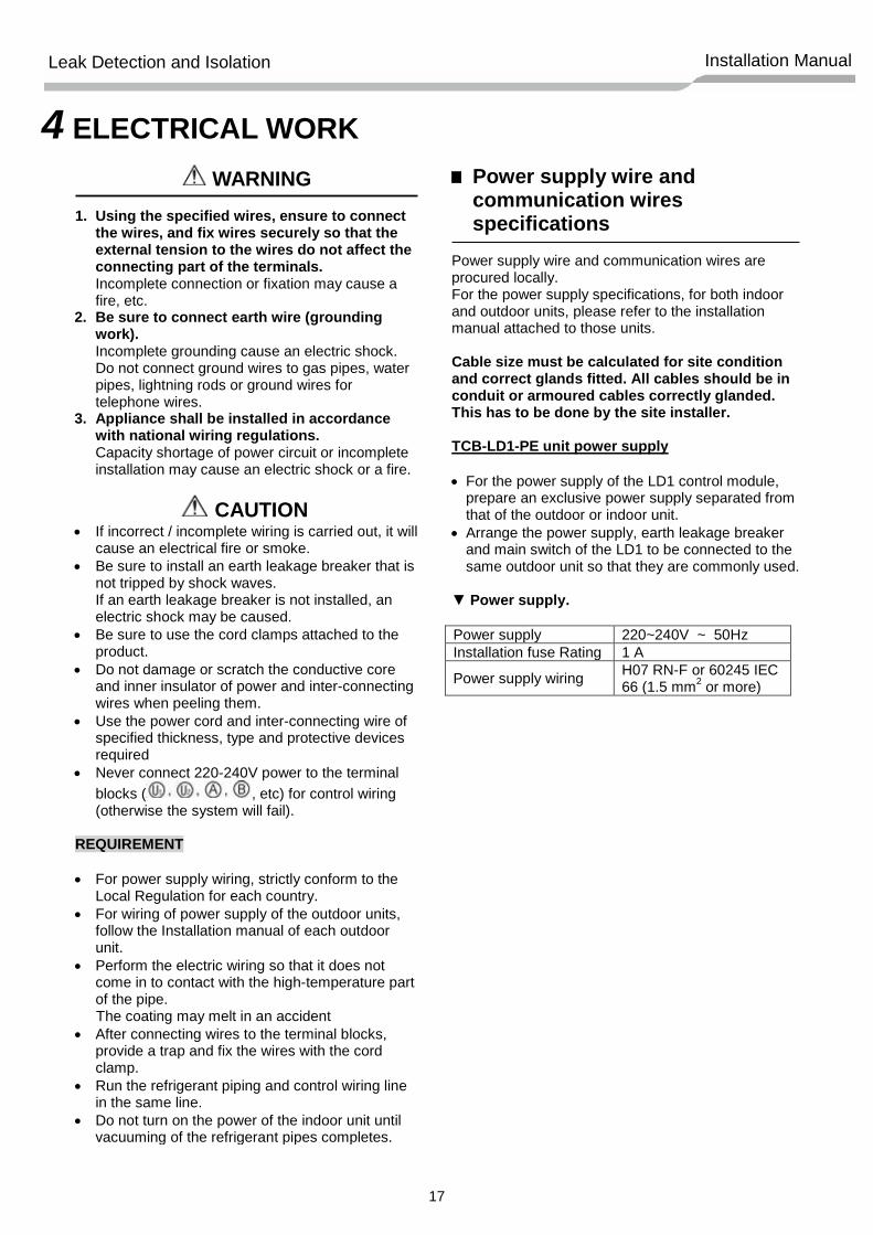
Power supply wire and communication wires specifications
Power supply wire and communication wires are procured locally. For the power supply specifications, for both indoor and outdoor units, please refer to the installation manual attached to those units. Cable size must be calculated for site condition and correct glands fitted. All cables should be in conduit or armoured cables correctly glanded. This has to be done by the site installer.
TCB-LD1-PE unit power supply
• For the power supply of the LD1 control module,
prepare an exclusive power supply separated from that of the outdoor or indoor unit.
• Arrange the power supply, earth leakage breaker and main switch of the LD1 to be connected to the same outdoor unit so that they are commonly used.
▼ Power supply.
Power supply 220~240V ~ 50Hz Installation fuse Rating 1 A
Power supply wiring H07 RN-F or 60245 IEC 66 (1.5 mm2 or more)
18
Leak Detection and Isolation Installation Manual
LDS1 and LDS2 PCB
AC/DC AC/DC NO COM NC
1 2 3 4 5 1 2 3 4 5 6 7 8 9 10 11 12
LD1 PCB
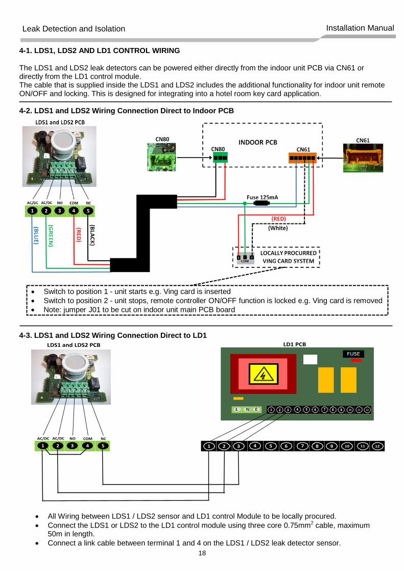
4-1. LDS1, LDS2 AND LD1 CONTROL WIRING The LDS1 and LDS2 leak detectors can be powered either directly from the indoor unit PCB via CN61 or directly from the LD1 control module. The cable that is supplied inside the LDS1 and LDS2 includes the additional functionality for indoor unit remote ON/OFF and locking. This is designed for integrating into a hotel room key card application. 4-2. LDS1 and LDS2 Wiring Connection Direct to Indoor PCB
• Switch to position 1 - unit starts e.g. Ving card is inserted • Switch to position 2 - unit stops, remote controller ON/OFF function is locked e.g. Ving card is removed • Note: jumper J01 to be cut on indoor unit main PCB board
4-3. LDS1 and LDS2 Wiring Connection Direct to LD1
• All Wiring between LDS1 / LDS2 sensor and LD1 control Module to be locally procured. • Connect the LDS1 or LDS2 to the LD1 control module using three core 0.75mm2 cable, maximum
50m in length. • Connect a link cable between terminal 1 and 4 on the LDS1 / LDS2 leak detector sensor.
19
Leak Detection and Isolation Installation Manual
1 2 3 4 5 6 7 8 9 10 11 12
LD1 PCB
CN80
INDOOR PCB
(RED)
(BLUE)
LD1 PCB
1 2 3 4 5 6 7 8 9 10 11 12
90o
45o
90o
MUELLER
90o
45o
90o
MUELLER
ISOLATION VALVE
Liquid Pipe Gas Pipe
(RED)
(PURPLE)
(ORANGE)
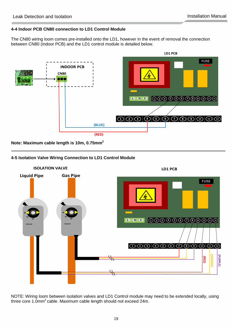
4-4 Indoor PCB CN80 connection to LD1 Control Module The CN80 wiring loom comes pre-installed onto the LD1, however in the event of removal the connection between CN80 (indoor PCB) and the LD1 control module is detailed below.
Note: Maximum cable length is 10m, 0.75mm2 4-5 Isolation Valve Wiring Connection to LD1 Control Module
NOTE: Wiring loom between isolation valves and LD1 Control module may need to be extended locally, using three core 1.0mm2 cable. Maximum cable length should not exceed 24m.
20
Leak Detection and Isolation Installation Manual
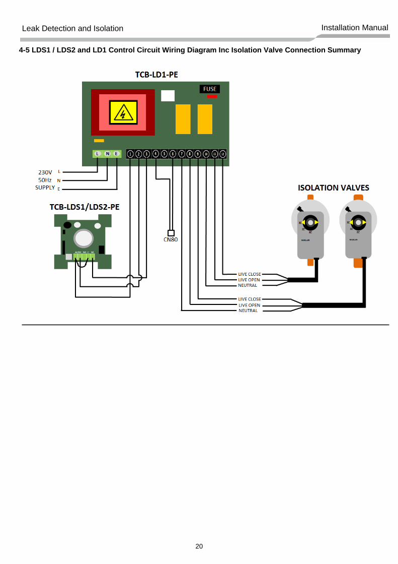
4-5 LDS1 / LDS2 and LD1 Control Circuit Wiring Diagram Inc Isolation Valve Connection Summary
21
Leak Detection and Isolation Installation Manual
LDS1Sensor
FCU Thermal
L30Fault Code
Isolation Valve
STAGE ONE ALARM ACTIVATION
Refrigerant Concentration Level
1000PPM
0PPM
ON
ON
OFF
OFF
ON
OFF
CLOSED
OPEN
TIME
0 30 60 90 120 150 180Minutes
121.5
Refrigerant Concentration Level
LDS1Sensor
FCU Thermal
L30Fault Code
Isolation Valve
STAGE TWO ALARM ACTIVATION
4000PPM
0PPM
ON
ON
OFF
OFF
ON
OFF
CLOSED
OPEN
TIME
0 30 60 90 120 150 180Minutes
121.590.5
5 OPERATION TIMING DIAGRAMS
22
Leak Detection and Isolation Installation Manual
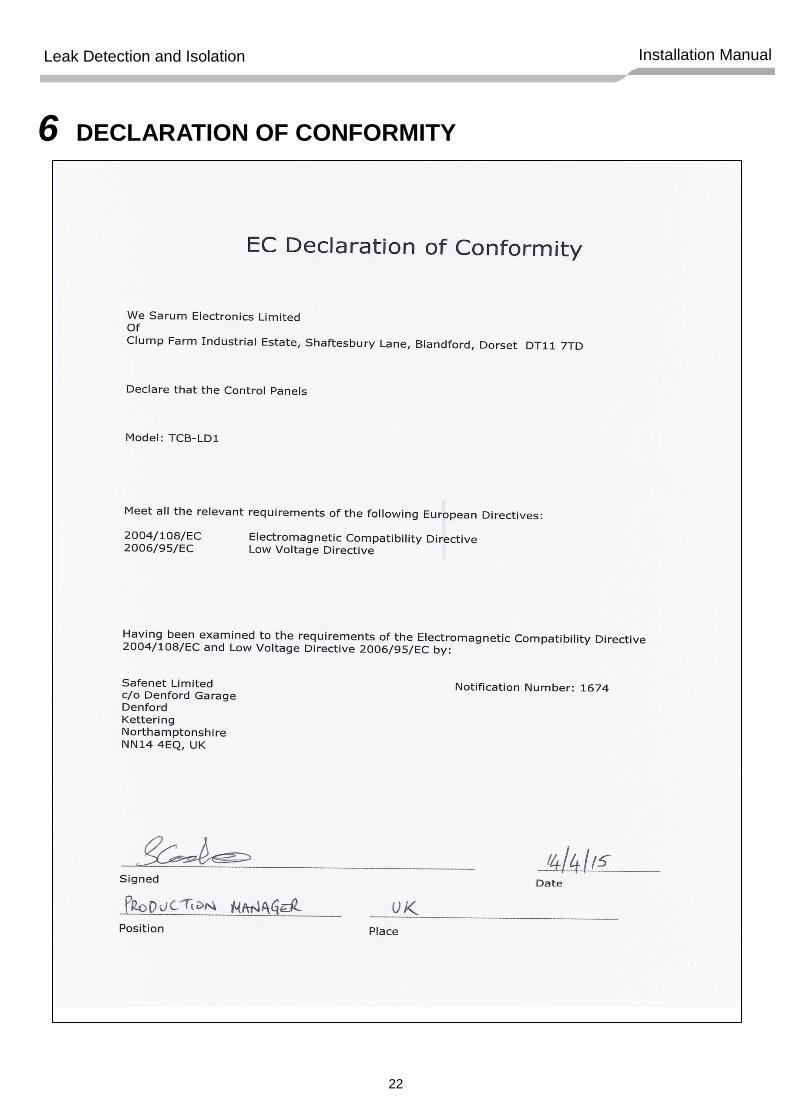
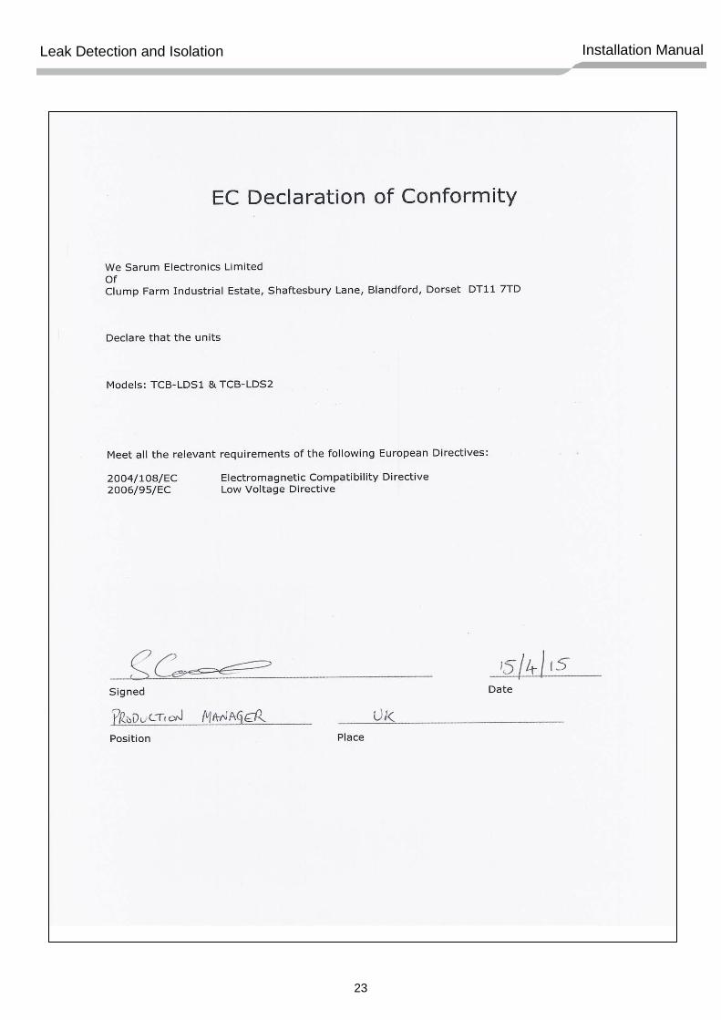
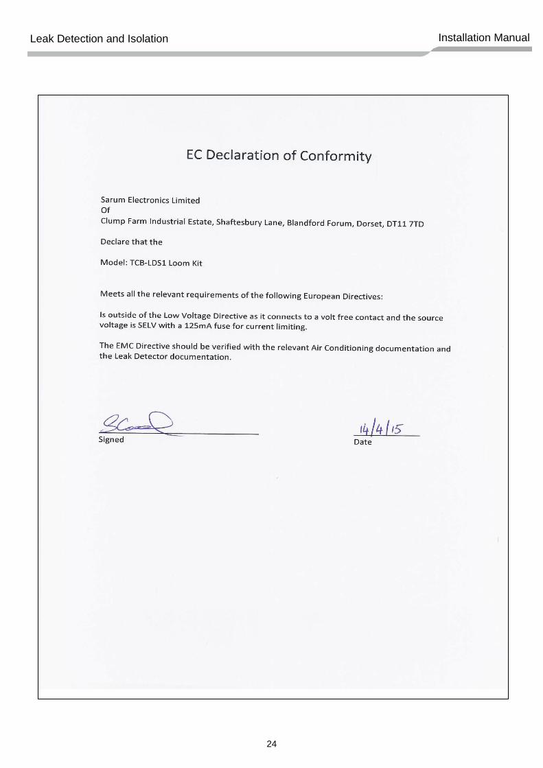
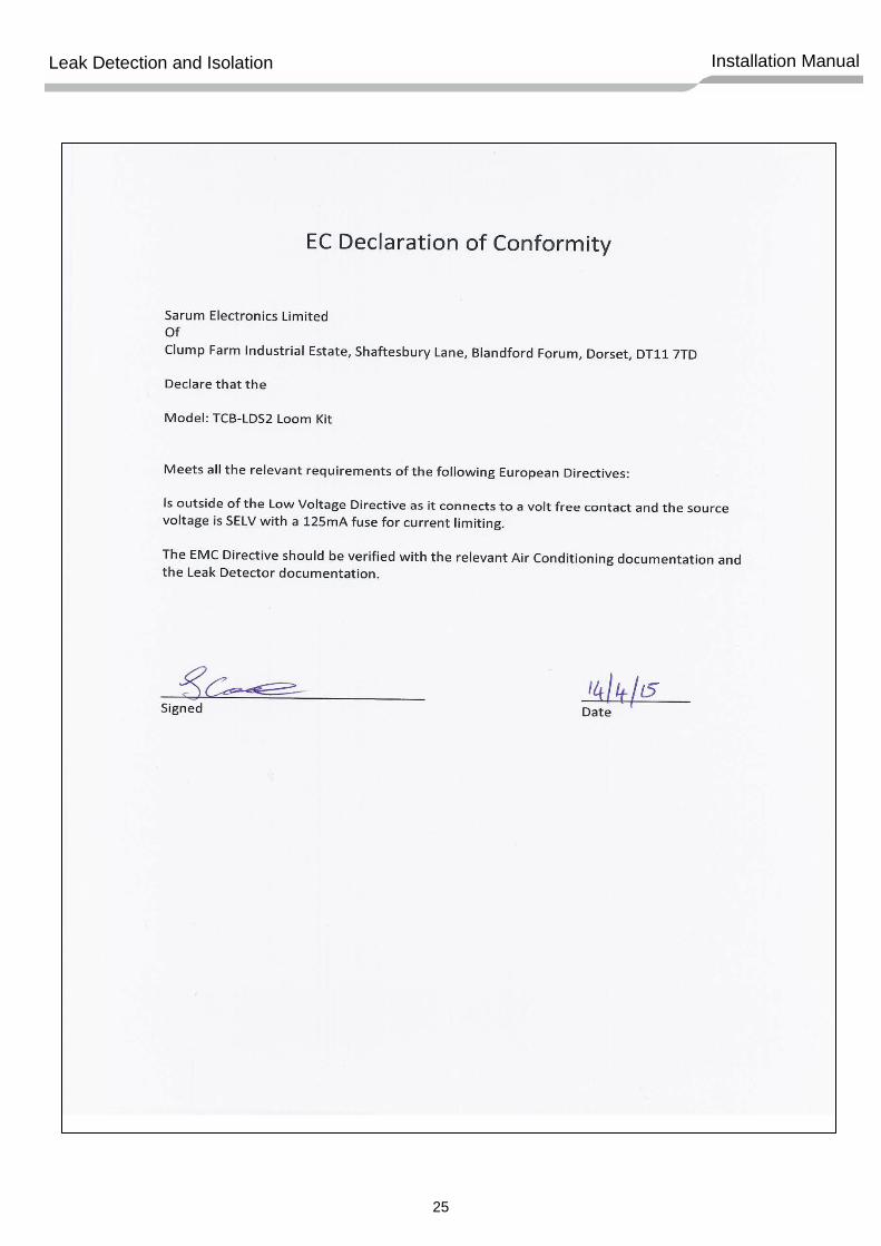
6 DECLARATION OF CONFORMITY
23
Leak Detection and Isolation Installation Manual
24
Leak Detection and Isolation Installation Manual
25
Leak Detection and Isolation Installation Manual
Toshiba Carrier (UK) Ltd Porsham Close Belliver Industrial Estate Plymouth Devon United Kingdom PL6 7DB