+ All Categories
Home > Documents > LEAK DETECTION WITH COATINGS Control No. DCN 1-1 … · Control No. DCN 1-1-60-0010(IF) February 19...

LEAK DETECTION WITH COATINGS Control No. DCN 1-1 … · Control No. DCN 1-1-60-0010(IF) February 19...

Date post: 23-Apr-2018
Category:
Upload: buinhi
View: 216 times
Download: 3 times
Share this document with a friend
64
\'J \ Report 5300-71-20 qecember 1 a" 1971 ' LEAK DETECTION WITH COATINGS Final report on Contract NAS 8-26761 Control No. DCN 1-1-60-0010 (IF) February 19 to December 18, 1971 (PAGES) (ACCESSION NUMBER) <;;3/15 Details ofiUustrations In thla document may be better studied on mic:rofich:e 2965 PEAK AVE. P.O. BOX G, BOULDER, COLORADO 80302 PH. 303-443-4660 LABORATORIES Feb. Reproduced by NAi10NAL TlECHNICAL INFORMATION SERVICE U S Deportment of Commerce Springfield VA 22151 C'l o 0() GO: o ')0 5 , (NASA CR OR TMX OR AD NUMBER) '(NASA-CR-123532) LEAK DETECTION WITH EXPANDABLE COATINGS Final Report 19 - 1 Dec: 1971 (Hauser Research Enql.neerl.ng Co.) 18 Dec. 1971 61 13L P https://ntrs.nasa.gov/search.jsp?R=19720010844 2018-06-08T13:25:08+00:00Z
Transcript

\,~)\'J \

Report No~. 5300-71-20

qecember 1a" 1971 '

LEAK DETECTION WITH ~XPANDABLE COATINGS

Final report on Contract NAS 8-26761Control No. DCN 1-1-60-0010 (IF)

February 19 to December 18, 1971

(PAGES)

(ACCESSION NUMBER)<;;3/15

Details ofiUustrations Inthla document may be better

studied on mic:rofich:e

2965 PEAK AVE. P.O. BOX G, BOULDER, COLORADO 80302 • PH. 303-443-4660

~A.USER~ LABORATORIES

Feb.

Reproduced by

NAi10NAL TlECHNICALINFORMATION SERVICE

U S Deportment of CommerceSpringfield VA 22151

C'lo0()

~GO:o~

')0

5, ~ (NASA CR OR TMX OR AD NUMBER)/~

'(NASA-CR-123532) LEAK DETECTION WITHEXPANDABLE COATINGS Final Report 19- 1~ Dec: 1971 (Hauser Research a~dEnql.neerl.ng Co.) 18 Dec. 1971 61~SCL 13L P

https://ntrs.nasa.gov/search.jsp?R=19720010844 2018-06-08T13:25:08+00:00Z

,I

NOTICE

THIS DOCUMENT HAS BEEN REPRODUCED FROM TH.E

BEST COPY FURNISHED US BY THE SPONSORING

AGENCY. ALTflOUGH IT IS RECOGNIZED THAT CER-

TA IN l?OR T IONS ARE IL LP.;GIBLE. IT IS BE ING RE­

LEASED IN THE INTEREST OF MAKING AVAILABLE

AS MUCH INFORMATION AS POSSIBLE.

Report No. 5,30P-71-20 '

December 18, 1~71

LEAK DETECTION WITH EXPANDABLE COATINGS

Final report on Contract NAS 8-:26761Control No. DCN 1-1-60-00100 (IF)

February 19 to December 18, 1971

by

Hauser Laboratories, Boulder, ColoradoDr. Ray L. Hauser, Research DirectorDr. Mary C. Kochansky, Chemist

Abstract

Objective of this study was to develop and evaluate a sy~tem for leak detectionthat' could be easily appl ied over separable connectors and that "",ould expand into a

, bubble or balloon if a leak were present. This objective was accomplished using thinfilms of Parafilm tape wrapped over connectors, which were then overcoated with aspecial formulation. The low yield strength and the high elongation of the envelopepermit bubble formation if leakage occurs. This system may be appropriate for weldsand other hardware besides separable connectors. The practical limit of this systemappears to be for leaks exceeding 10-6 cc/sec. If this envelope is used to trapgases for mass spectrometer inspection, leaks in the range of 10-8 cc/sec. may bedetectable.

FOREWORD

This report was prepared by Hauser Laboratories under contract

NAS 8-26761 for the George C. Marshall Space Flight Center

of the National Aeronautics and Space Administration. The

work was administered under the technical di rection of the

Quality & Reliability Assurance Laboratory of the George C.

Marshall Space Flight Center.

CONTENTS

Page

I. Introduction

II. . Concepts

III • Formulations and Application Properties 4

A. Coating Materials 4

B. Release Materials 7

C. Adhesive Materials 8

IV. Mechanical Properties of Coatings 8

A. Selection Criteria 8

B. Test Methods 9

C. Test Resu Its 10

V. Performance Tests 11

A. Apparatus 11

B. Appl ication 12

C. Results 13

D. Reliability & Sensitivity 14

E. Removal 15

VI. Conclusions 16

-TABLES

l. Formulas and Applications of Coatings 17 - .,

2. Sources of Materials Used in Formulations 39

3. Release Materials 40

4. Adhesive Materials 41 ,.

5. Mechanical Properties of Coatings 42

6. Performance of Leak Detection Systems 46

FIGURES

1. Effects of Polypropylene Wax Added to Kraton Rubber Formulations

2. Effects of Chlorowax 70 Added to Kraton 1101 Rubber

3. Effects of Four Plasticizers Added to Kraton 1101 Rubber with 150 phrChlorowax 70

4. Comparison of Three Different Kraton Rubbers used with 150 phrChlorowax 70 '

5. Effects of Plasticizers and Waxes Added to Vinyl Resin VYHH andParaplex G-62

6. Performance of Leak Detection System Under Water

7. Step-wise Appl ication of Parafi 1m Release Tape and ExpandableCoating for Leak Detection System

52

53

54

55

56

57

58

I

I. INTRODUCTION

All missiles using liquid propellants have a large amount of piping using

separable connectors. Each separable connector is a potential cause of leakage,

and any leakage can be a serious malfunction. Rapid and sensitive detection of

leaks at such connectors is thus a major concern for proper quality assurance

and missile reliability.

Use of expandable coatings over separable connectors is a novel approach

to the problem of leak detection, and this study was aimed toward developing

materia Is appropriate for this purpose. The objective was to develop a system of

coating/adhesive/release materials which could be tightly conformed over a sep­

arable connector and which would then form blisters or bubbles if the joint were

to leak when pressurized. This blister or bubble should then be easily identified

as a leakage point I and the material should be easily removable from the con­

nector after tests have been completed.

II. CONCEPTS

In many respects, the ideal material for this leak detecting coating would

be a solid-phase soap bubble -- a material that could be painted.on easi Iy, and

that would deform easily when pressurized. But unlike a soap bubble, the mate­

rial would have long-term durabil ity for tests that might last for at least several

hours.

The mechanical properties of this ideal material would include low yield

strength (in biaxial tension) and very high elongation (again biaxial tension) prior

to rupture or pinhole formation.

Application properties of the ideal material would include opportunity for

easy brushing over the connectors, rapid drying, and almost impossible flow char- .

acteristics -- smooth, uniform coverage over rough surfaces such as pipe threads

and the ability to not flow into cracks and crevices.

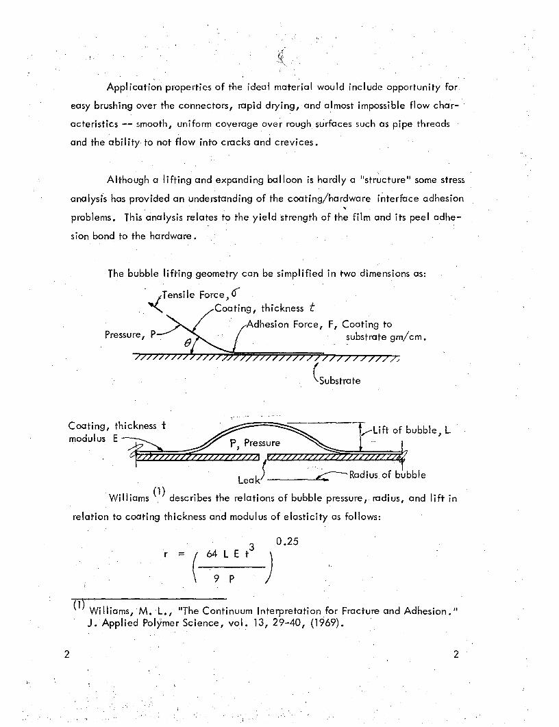
Although a lifting and expanding balloon is hardly a "structure" some stress

analysis has provided an understanding of the coating/hardware interface adhesion~

problems. This analysis relates to the yield strength of the film and its peel adhe-

sion bond to the hardware.

The bubble lifting geometry can be simplified in two dimensions as:

-_,Tensile Force) 0~ Coating, thickness t

Adhesion Force, F, Coating tosubstrate gm/cm.

(Substrate

Coating, thickness. t ~~;ft. of bubble) L

modulus E~ . . P, Pressure ..' ... t' ~~A~777Z2Z6

. . Leak) '~Radiusofbubble

. Williams (1) describes the relations of bubble pressure, radius, and lift in

relation to coating thickness and modulus of elasticity as follows:

r -.-

(

64 L E t3

9 P)

0.25

2

(1) Williams, M.L., liThe Continuum Interpretation for Fracture and Adhesion. II

J. Applied Polymer Science, vol. 13,29-40, (1969).

2

The equation is applicable only for a very small amount of lift, and this condition

truly exists if there is no transition in the adhesion of coating to substrate. Once

pre~sure P has caused L to become Finite, r has a finite value. The flatwise

radius of the bubble can be maintained at a pressure less than the initial lifting

pressure (since P is in the denominator of the above equation). In other words,

the condition is unstable -- if lift is initiated, r wi II continue increasing unti I

the edge of the coating is reached, and then the bubble will teak at its edges.

This analysis underscores the importance of having a demarcation in the

adhesion of coating to substrate -- a higher peel strength at the edges where

seal is to be maintained than at the leak area where the bubble is expected to

lift.

If the tensile force on the bubble (at any angle Q) exceeds the adhesion

bond (at the same angle) of cocHing to substrate, the coating will lift slightly,

leak at its edges and fail to indicate a leaking connector.

In order for the bubble to maintain its seal and grow by stretching, the

yield strength of the bubble material must be low in relation to its adhesion peel

strength to the substrate c This requirement is expressed mathematically as:

() 4( F/t where Oy = tensile yield strengthy of the coating, gm/sq. cm

F = adhesion to substrategm/cm

t = coating thickness, em

3 3

In order to obtain ,this demarcatloni~ adhesive bond to the substrate,

two combinations of materials can be used:·

a. A release material placed under the coating in the areas

where ballooning is desired, and a coating with fair

adhesion to the substrate.

b. a coating with poor adhesion (easy release) to the sub­

strate and a separate adhesive material applied at the

interface where the bubble seal is desired.

Both concepts in materials'combinations have been studied on this contract.

III. FORMULATIONS & APPLICATION PROPERTIES

Coatings, releases and adhesive materials were studied inde­

pendently and then they were tested in combination for lea kage performance

tests. Major emphasis was given to the coatings.

A. Coating Materials

A large number of coating materials were considered, many were tried,

and a few were tested. These studies started with some materials pn the lab­

oratory shelves and the scope was expanded as time and search indicated other

prospects.

Thermoplastic elastomers and plasticized vinyl resins were the main

. emphasis in materials selection and formulation. The block copolymer of sty­

rene and butadiene (Shell Kraton rubber) and thermoplastic urethanes were

known to have highelongation and relatively high creep characteristics.

Whereas the creep or viscous Component of'these polymers is often excessive

4 4

5

for mechanical applications, these elastomers were much too elastic by themselves

and required a fair amount of modification with waxes and plasticizers.

An expanding bubble toy has intriguing characteristics pertinent to this

study, and "Super Elastic Bubble Plastic" was given some consideration. Infra­

red spectral analysis revealed that this material was a vinyl acetate polymer.

Whereas the material expands easily into an air-blown bubbl~, it quickly loses

its solvent and forms a relatively hard, non~tacky bubble. Reformulation with

permanent plasticizers rather than solvent might provide a practical expandable

coating. Several vinyl formulations were prepared following recommendations

of Union Carbide Corporation, Diamond-Shamrock Corporation and others.

Special additives were sometimes used to modify the surface tackiness,

coating/substrate adhesion, flow characteristics or appearance. NP Antidust

was used mostly as an anti-tack, and Zelec UN was used as an internal release

additive to decrease the substrate adhesion of coatings.

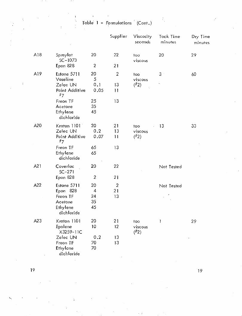
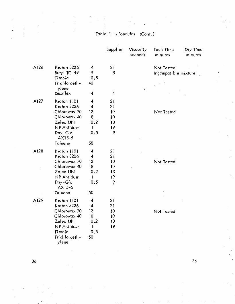
A total of 136 formulations were outlined, as noted in Table 1, page 17.

As each formulation was prepared, the application characterisitics were noted

quantitatively and some adjustments were made immediately. Quick screening

tests .were frequently made to learn whether a good film was formed, and whether

the coating had attractive properties of elongation and adhesion or release.

If the coating looked like a good prospect, its viscosity, tack time and

dry time were measured. First viscosity tests were made with ci Shell #2 viscosi­

. meter, but most coatings were too viscous or dried (and plugged) too fast for this

instrument. Shell #4 cup was used for most viscosity tests.\

These application properties are noted in Table 1 along with the formu­

lations. The number-coded suppliers of materials (except some· common labora­

tory solvents and pigments) are noted in Table 2, page 39 •

5

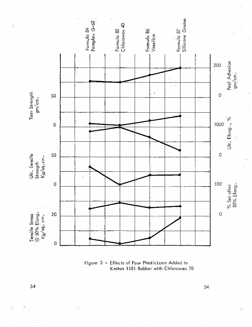
A number of parametric studies were made after good prospects had been

identified. Four of these studies used Kraton elastomers with different amounts

or types of wax or plasticizer additives. Figure 1, page 55 shows the effects

of a polypropylene wax added to Kraton 1101. Figure 2, page 56 shows the

very desirable attributes obtained by addition of Chlorowax 70 to Kraton 1101.

Four plasticizers were then compared for the Kraton/Chlorowax-70 system in

Figure 3, page 57. Finally the two alternative Kraton elast9merS were com­

pared with Kraton 110 1 in Figure 4, page 58. All these studies used quanti­

tative mechanical properties for comparison as follows:

Stress at 50% elongationPermanent set after 50% elongation'Ultimate tensile strengthUltimate elongationTear strength900 peel adhesion strength

Details for these tests are discussed below in Para9raphIV~A.

A similar set of parametric studies was performed for the Bakelite VYHH

vinyl resin with a vari~ty of plasticizers and waxes. These data are shown in

Figure 5, page 59 •

Formula 105 was one of the best coatings of the study, and several vari-. -

ations were made therefrom. Dyes, Day-Glo pigments and solvents varied until

Formula 130 was considered to provide the best combination ,of appl ication and

performance characteristics.

Subsequent formulations combining the coating in an aerosol with Pro­

pellant #12 indicated feasibility for spray application, but this alternative was

not pursued to optimization.

6 6

',t

B. Release Materials

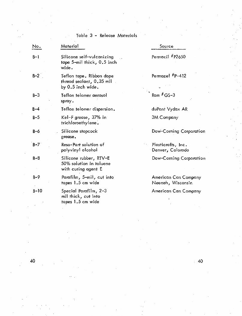
Ten different tape and coating type releases were evaluated in this program,

as outlined in Table 3, page 40 •

The tapes were selected for ready conformability to the:geometry of separ­

able connectors. The self-vulcanizing silicone tape formed an excellent seal and

release from the hardware, but coatings usually bonded to the silicone tape and

reacted in an elastic manner because of the tape elasticity. The Teflon tape gave

good release from both the hardware and the coating, but edges of this tape were

too sharp and coatings were cut at these points.

None of the paint-on release materials was adequate.' A greasy or non­

wetting surface caused difficulties in the subsequent coating operation.

The best release material was Parafilm tape in" 2-:-3 mil thickness. Para­

film is a waxy film that has high plastic elongation and a very low yield strength.

When this material was used as a release tape, it could be stretched easily and

then conformed tightly to the separable connector •. Overcoats of the coating

formulation bonded to the Parafilm, and the coating solvents helped to seal

toge~her the edges of the Parafilm. Parafilm and overcoating deformed together

during pressurization, discussed below in Paragraph V-C.

The commercial Parafilm tape is produced in 5-mil thickness. Laboratory

samples of 2-3 mil' Parafilm were made by stretching the film about 100% between

two sets of rollers. Delivery, samples were made by the manufacturer, Ame.rican

Can Company, in a special production run.

7 7

C. Adhesive Materials'

Seven adhesives were tried, as noted in Table 4, page 41 . These adhesives

were used only with coatings that had good release characteristics. Final formulations

had adequate adhesion of coating to substrate and no adhesive was used in the final

leak detection system.

The double tacky tape was ineffective when placed on hex nuts, due to lifting

at the sharp bends. Otherwise each of the adhesives could be used with the'appro­

priate type of coating (e.g. vinyl adhesive for vinyl coating and rubber adhesive for

rubber coating).

IV. MECHANICAL PROPERTIES OF COATINGS

Pertinent tests were performed to evaluate in quantitative tenns the mechanical

properties of coatings. Test methods, results and selection criteria are discussed below.

A.' Coating Selection Criteria

Tests were selected to identify those characteristics of the coatings that were

most important in performance of leak detection objectives. Properties of low yield

strength and high plastic elongation were considered to be essential. High tensile

and tear strength would be helpful. Low or moderate peel adhesion strength would

be needed, respectively, for a release coating or for an adherent coating. Tests and

criteria are outlined below:

1. Tensile stress at 50% elongation.

Bubbles or blisters with 50% stretch of the film would be easilyidentified. A low stress at this elongation would signify lowyield strength and easy distension of the bubble, preferably lessthan 30 Kg/sq .cm.

8

, .~.

8

2 • Permanent set after 50% elongation.

After the film has been stretched 50% and the load or pressureis decreased to zero, the film should not return in an elasticmanner to original dimensions. A high permanent set wouldbe desirable, preferably exceeding 50% of the stretch.

3. Ultimate tensile strength of the film may be of some signif­icance, particularly in relation to toughness and durabilityduring handling. A moderate ultimate tensile strength mightp'rovide a fair balance of durability and ease 'of removal.Strength between 1 and 30 Kg/sq.cm. was considered

.appropriate.

4. Ultimate elongation of the coating film was desired to be ashigh as possible, commensurate with other attributes. Elong­ation of 200% was considered to be the minimum acceptable.

5. Tear strength was desired to be a maximum, for best durabilityof the coating. This characteristic was considered secondaryto the extensible properties noted above.

6. Peel adhesion was desired to be below 100 gm/cm for use asa release coating and above cry t gm/cm if the coating wasto be its own adhesive" As in Par. II above, Oy t is the

. product of the film yield strength and the film thickness.

B. Test Methods

The coating formulations were painted onto a release surface in order to

obtain free films for testing. In most cases, polyethylene was used as the release

surface, but with many of the Kraton/Chlorowax formulations no good adhesive

surface was found. For these coatings, heavy paper was sized with animal glue

prior to brush coats of the test formulation. Free films were then obtained by

soaking the paper in water.

Tensile and tear test specimens were die-cut from these films. The tensile

tests used specimens described in ASTM D412 and tests were performed at the rather

slow crossh~ad speed, 5 em/minute (2 inches per mi~ute). This permitted the oper­

ator to stop the test at the first 50%.elongation, reverse the crosshead to learn

,.

9 9

permanent set and then continue the test to learn ultimate strength and ultimate

elongation. The force and crosshead position were recorded continuously during

these tests.

Tear strength tests were performed according to ASTM 0624, die C with

crosshead a rate of 5 em/minute (2 inches/minute). The maxj~um tear force

was recorded, per unit of specimen thickness.

The peel adhesion specimens were made by coating a stainless steel

coupon 2.5 em x 15 em with two coats of the formulation. Then a cotton

tape was placed onto one end of the coating and two more coats were appl ied.

The tape was pulled at 900

angle to the stainless steel coupon at a rate of 5

em/minute (2 inches/minute) and force was recorded continuously. Average

peeling force per unit width was reported •.

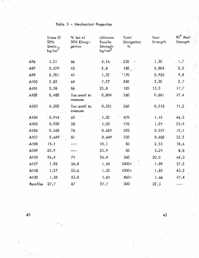
C. Results of Mechanical Tests

Coatings were tested with three replicate specimens and averages are

reported in Table 5, page 45 • Some of these data were discussed above in

Figures 1-5.

As might be expected, this wide variety of coatings had properties that

ranged from cheesy and sleazy to rough and tough. Some of the highly plasti­

cized vinyl coatings would hardly support the weight of the dumb-bell shaped

test specimen •.

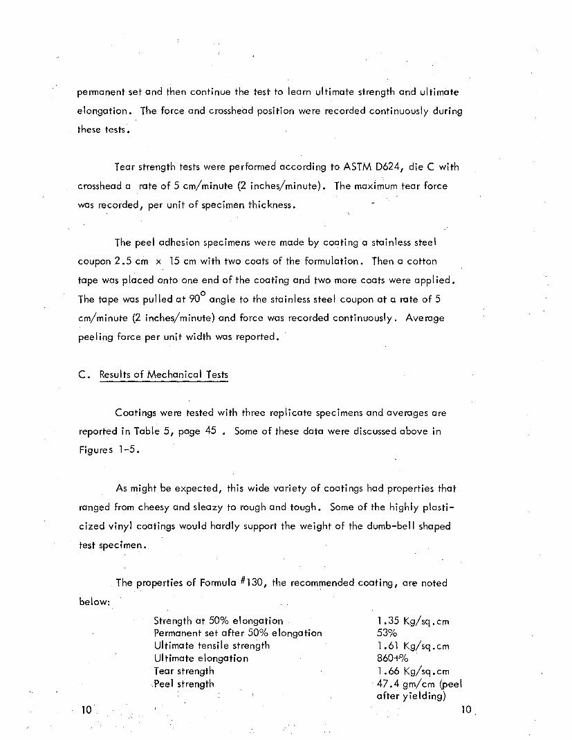
The properties of Formula #130, the recommended coating, are noted

below:

Strength at 50% elongationPermanent set after 50% elongationUltimate tensile strengthUltimate elongationTear strength·Peel strength

1.35 Kg/sq.cm53%1.61 Kg/sq.cm860+%1.66 Kg/sq.cm47.4 gm/cm (peelafter yielding)

10

Parafi 1m is another component of the recommended leak detection system

and its properties are:

Strength at 50% elongationPermanent set after 50% elongationUltimate tensile strengthUltimate elongationTear Strength

V. PE RFORMANCE TESTS

27.7 Kg/sq .cm.87%27.7 Kg/sq .cm.200%22.3 Kg/sq .cm.

Tests were prepared to simulate the performance of the leak detection" systems.

These tests used separable connectors with the detection systems applied thereupon.

A. Performance Test Apparatus

Six sets of ten separable connectors were prepared using 1/2-inch stainless

tubing with flare and f1areless connectors. Each connection was mutilated with a

groove by a triangular file so that it would leak. The ten connections were assembled

with a quick disconnect fitting to provide rapid assembly for pressurization.

To evaluate the opportunity of handling different sizes of separable con­

nectors, two additional "Christmas trees" were prepared using tubes of diameter

1/8 to 1" and a variety of step adapters. These also had a quick disconnect fitting

for pressurization.

Air was used for pressurization of these test units, and a pressure regulator/

gauge combination was used at the unit. This permitted gradual increase in pres­

sure for each test.

Perfor

Performance tests were norma Ily performed with the connectors under water,

Figure 6, page 60. If air bubbles were observed without an obvious distension of the

coating, the leak detector was faulty. If distension was observed, a pinhole or burst

11 11

failure would usually follow, and then bubbles would be observed. If neither distension

nor air bubbles were noted, the coating system had closed off the leak. Sometimes this

could be opened up at higher pressures (60 psi was the maximum pressure used), but if

no leakage was obtained, the connector was considered to be "no test".

B. Application of Leak Detection Systems

First tests of the coatings were made by brushing or taping the appropriate

release and/or adhesive and then by brushing on the extensible coating usua Ily

using two coats. The coating was allowed to dry overnight and then it was tested

under water as noted above.

The number of distended bubbles or blisters and the number of leaking

fittings were noted for each leak detection system. The lift distance was also

noted for each bubble or bl ister.

As the detection systemsdeveloped, the combination of an extensible

release tape and an extensible coating looked more and more attractive. The

recommended system uses 3-mil Parafi 1m as a release tape and coating #130 as

an overcoat.

The materials used for the recommended system consist of the following:

Parafilm tape, 3-mil thick by 1.5 cm wide by 8-10 cm long.Tape tightener -- a bundle of 10-15 elastic threads 20 cm.

long, made of #600 Nylon elastic threads(Scoville Oritz)

Expandable coating, formula #130Artists paint brush, #49 Fitch Fan

12 12

~

Figure 7, page 61 illustrates the four steps forapplication of the leak detection

system:

A. A strip of Parafilm tape is pulled tightly against the tubing at oneedge of the separable connector at least 2 mm beyond threads, in­sert or nut. The short end of the tape is pulled tightly against thetube and then it is folded toward the nut. The first wrap of the tapecovers this short end.

B. The tape is wrapped around nut and threads,' pulled tightly into ahelical pattern with at least 3 mm overlap for each turn. The topeis pulled tightly as it makes the transition between nut and threaddiameter. Tape is terminated at a distance 3-4 mm beyond the lastthread or insert. Termination is accomplished by stretching theParafi 1m tape and breaking it at the tube.

The Parafilm tape wrap is now inspected to insure that a complete"mummy wrap" exists with no holidays.

C. Void volume within the Parafilm tope wrap must be minimized.To do this, the bundle of elastic threads is wrapped around thefitting at threads, inserts, bridges, or any place where the fi 1mis not in close contact with the hardware.

The tape wrap is again inspected to insure that complete, void­free envelope.

D. A smooth brush coat of the coating #130 is applied over the Para­film tape, extending 2-3 mm onto the tubing or fitting. After a2-3 hour dry, a second brush coat of #130 is appl ied.

After the coating has dried 12-16 hours it should be inspected toinsure that complete coverage has been obtained and to insuretha t the edges of the Pa ra fi Im to pe have been sea Ied by thecoating.

E. During or after system pressurization, the expanded bubble isinspected by both visual and tactile senses. If the bubble isnot obvious, a finger can discern whether the film has liftedfrom the hex nut of the separable connector.

c .. Results of Performance Tests

About 500 connectors were coated with various combinations of releases,

adhesives and expan~able coatings. Results of these tests are presented in Table 6,

page 49 •

13 13

In this table, the fraction of identifiable leaks (balloon bubbles) and the

Iift distance for these bubbles are the measures of performance.

Coating #130 with release #B10 provided the best and most consistent leak

detection performance. Application of this system was described above. Bubbles

were readily discerned in 105 of the 107 separable connectors where it was applied.

Insufficient coverage of the coating #130 was cause for nondetection in the two

tests, and insufficient inspection was cause for nondetection of the coverage.• This

was due to a violation of Quality Control Commandment #1 -- liThe operator and

the inspector shall be different persons responsible to different authorities."

Coating #134 was applied by aerosol over Parafilm tape, release BlO, and

it was effective in 7 of 9 connectors. This indicated the feasibility of aerosol appli­

cation, but #134 was probably not an optimum formulation.

D. Reliabil ity and Sensitivity of Leak Detection Systems

The recommended leak detection system described above appears to be highly

r"eliable for large leaks when applied and inspected properly.

-4The smallest of the 107 leaks was measured to pass air at the rate of 2 x 10

cc/sec. (measured by water displacement). This leak was easi Iy discernible with

the expandable coating within a period of 1 hour.

Gas transmission rate of the Parafilm/#130 coating system was measured as

2670 cc/sq. meter 24 hr. atm. Since the coating over a hex nut of 0.5" diameter

requires only 360 gm/sq.cmo or 5.1 psi pressure to couse yielding and ballooning,

14 14

the permeation pressure can not exceed this value. Thus the leak detection limit of. -7

this system is in the range of 7 x 10 cc/sec. The practical time limit of this sys-

tem may be somewhere in the range of 10-6

cc/sec. over a period of 24 hour pres­

surization (0. 1 cc. accumulation).

A further improvement is obvious in the area of application inspection. Since

two coats of formula #A130 are used, the first coating would~be better with an opaque

white pigment and the second coating would be better with the Day-Glo pigment.

This would provide an extra opportunity for inspecting the rather critical asPect of

complete coverage by the coatings.

This leak detection system may be valuable in combination with mass spectro-

meter methods for extremely sensitive inspection. The envelope provided by this

system could entrap the gases from a minute leak, and a hypodermic needle probe

inserted into the envelope could identify the accumulation of this leakage. Such

a system may be sensitive to 10-8 cc/sec. leak rate. Concern should be given

to make sure that coating plasticizers do not interfere with the inspection system.

E. Removal of Leak Detection Systems

The unbonded portion of the leak detection wrapping is edsi Iy removed. A

fingernail easily pierces the coating and the material pulls off cleanly. At the end

where the coating is bonded onto the tubing, a rubbing action is needed to remove

the formulation. Alternatively or additionally, a wipe with a solvent-moistened

cloth quickly dissolves the residue.. Toluene or trichloroethylene may be used as

the solvent, depending upon concerns of flammabi Iity and vapor toxicity. "

15 15

VI. CONCLUSIONS

Contract requirements have been met in the development and evaluation of

an expandable coating system for leak detection. The system has not yet been eval­

uated in actual or simulated missile hardware to learn the practic;::ality of application

and the time/cost/reliability/sensitivity comparisons with alternative leak detection

systems.

Coating #130 with 3-mil Parafilm tape provides an expandable coating system

of leak detection that is sensitive to less than 10-6

cc/sec. leakage rate. It is

readily visible and easily inspected for detection of leaks by visual and tactile senses.

It is easi Iy removable after use. In conjunction with a mass spectrometer, this system

might provide 10-8

cc/sec. sensitivity.

Although the leak detection system was directed toward appl ication on sep­

arable connectors, it may also have considerable utility for leak inspection of welds

and other hardware. Slight modification of the tape/coating system could provide

"band-aid" simplicity in application of leak detection patches.

16 16

Table 1 - Formulas and Application Properties of Coatings

Supplier Viscosity Tack Time Dry Timeseconds minutes minutes

A1 RTV 102 20 °15Si Iicone grease 10 11 Not TestedFreon TF 35 13Ethylene 6.4

dichloride

A2 Parofi 1m 30 17 too 3+ hrs. 19+ hrs.Zelec UN 0.5 13 viscousFreon TF 35 13 (#2)Ethylene 235

dichloride

A3 R170857 3 14 Not TestedFreon TF 17.5 13 Incompatible mixtureEthylene 17.5

dichloride

A4 Coverlac 22 Not TestedA-1114

A5 H P Latex Not Tested

A6 Spraylat 22 Not TestedSC-1073

A7 Estane 5711 20 2Vaseline 5Zelec UN O. 1 13 Not TestedFreon TF 25 13Acetone 35Ethylene 45

dichloride

A8 Kraton 1101 20 21 Not TestedZelec UN 0.2 13Freon TF 65 13Ethylene 65

dichloride

A9 Kraton 1101 20 21 Not TestedVaseline 5Zelec UN 0.2 13Freon TF 70 13Ethylene 70

dichloride

17 17\,

Table 1 - Formulas (Cont. )

Supplier Viscosity Tack Time Dry Timeseconds minutes minutes

AlO Hypalon 30 50 13 too 2.5 6.5PPO #691-111 6 15 viscousModaflow 0.25 18 (#2)Titania 60G 6099 Green 6 6Trich loroeth- 218

ylene

All #11444 Tacki- 20 5 too 14.5 18+ hrs.wax viscous

Vaseline 5 (#2)Zelec UN 0.2 13Freon TF 45 13Ethylene 45

dichloride

A12 Chlorowax 70 20 10 too 48 2.5+ hrs.Freon TF 30 13 viscousEthylene 40 (#2)

dichloride

A13 Epolene 20 12 Not TestedX3259-11 B

Freon TF 65 13Ethylene 65

dichloride

A 14 Epolene 20 12 Not TestedX3259-11C

Freon TF 40 13Ethylene 40

dichloride

A15 Coverlac 22 Not TestedSC-271

A16 Goodrich latex 2 Not Tested60-457

A17 RTV 102 10 15 too 90+ 120+Silicone 10 11 viscous

greaseZelec UN 0.5 13 (#2)Freon TF 20 13Ethylene 10

dichloride

18 18

t!,.<

TableJ

1 - F.ormulations (Cont.)

Supplier Viscosity Tack Time Dry Timeseconds minutes minutes

A18 Spray lot 20 22 loo 20 295C-1073 viscous

Epon 828 2 21

A19 Estane 5711 20 2 too 3· 60Vaseline 5 viscousZelec UN O. 1 13 (#2)Paint Additive 0.05 11

#7

Freon TF 25 13Acetone 35Ethylene 45

dichloride

A20 Kraton 1101 20 21 too 13 33Zelec UN 0.2 13 viscousPaint Additive 0.07 11 (#2)

#7Freon TF 65 13Ethylene 65

dichloride

A21 Coverlac 20 22 Not TestedSC-271

Epon 828 2 21

A22 Estane 5711 20 2 Not TestedEpon 828 4 21Freon TF 24 13Acetone 35Ethylene 45

dichloride

A23 Kraton 110 1 20 21 too 29Epolene 10 12 viscous

X3259-11C (#2)Zelec UN 0.2 13Freon TF 70 13Ethylene 70

dichloride

19 19

Table, 1 - Formulations (Cont. )

Supplier Viscosity Tack Time Dry Timeseconds minutes minutes

A24 Kraton 1101 20 21 too 2 32Vaseline 10 viscousZelec UN 0.2 13 (#2)Paint Additive O. 14 11

#7Freon TF 65 13Ethylene 65

dichloride

A25 Chlorowax 70 50 10 too 56 7+ hrs.Trichloroeth- 25 viscous

ylene

A26 Kraton 1101 10 21Epolene 5 12 Not Tested.

X3259-11CZelec UN O. 1 13Trichloroeth- 100

ylene

A27 Kraton 1101 10 21 too 2 70+Vaseline 5 viscousZelec UN O. 1 13 (#2)Paint Additive 0.07 11

#7Trichloroeth- 65

ylene

A28 Estane 5711 10 2Vaseline 2.5 Not -TestedZelec UN 0.05 13Paint Additive 0.025 11

#7Trichloroeth- 35

yleneAcetone 17.5

A29 Spraylat 1073 20 22 too 18 37Day-Glo D13 1. 9 viscous

A30 Kraton 1101 10 21Epolene 7.5 12 Not TestedZelec UN O. 1 13Trich loroeth- 75

ylene

20 20

\ Table 1 Formulations >(Cont. ) \~

Supplier Viscosity Tack Time Dry Timeseconds minutes minutes

A37 Estane 5711 10 2 too 34 66Vaseline 2.5 viscousDioctyl phthalate 2 (#2)Zelec UN 0.05 13Paint Additive 0.025 11

#7Trichloroeth- 35

yleneAcetone 17.5

A38 Parafilm 15 17 too 4+ hrs.Day-Glo D13 1 9 viscousTitania 5 (#2)Toluene 85

A39 Estane 5711 20 2 too 6 15Vaseline 5 viscousDioctyl phthalate 2 (#2)Methyl ethyl 60

Ketone

A40 Parafilm 10 17 too 3.5+ hrs.Kraton 1101 5 21 viscous·Day-Glo D13 1 9 (#2)Titania 5Toluene 85

A41 Spraylat 20 22 too 10 31SC-1073 viscous

Day-Glo D13 0.5 9Dioctyl phthalate 2 (#2)

A42 Coverlac 20 22 too 12 19SC271 viscous

Dioctyl phthalate 2

A43 Spraylat 1519A 22 Not Tested

A44 Estane 5711 20 2Vaseline 5 Not TestedDioctyl phthalate 2 Incompatible mixtureMethyl iso-Butyl 60

Ketone

22 22

· ;'\-'

Table 1 - Formulas (Cont.)

Supplier Viscosity Tack Time Dry Timeseconds minutes minutes

A45 Kraton 1101 5 21 too 7 41Epolene 10 12 viscous

X3259-11C (#2)Trichloroeth- 75

ylene

A46 Kraton 1101 10 21 Not TestedEpolene 15 12

X3259-11CTrichloroeth- 75

ylene

A47 Kraton 1101 10 21 Not TestedChlorowax 70 10 10Trichloroeth- 70

ylene

A48 Kraton 1101 8 21 too 8 20Chlorowax 70 12 10 viscousTrichloroeth- 70 (#2)

ylene

A49 Bakelite VYHH 10 23 40 24 44Paraplex G-62 12.5 20 (#2)Chlorowax 70 12.5 10Methy iso- 30

Buty I KetoneToluene 30

A50 Kraton 3202 8 21 25 12 26Chlorowax 70 12 10Trichloroeth- 70

ylene

A51 Kraton 3226 8 21 109 7 31Chlorowax 70 12 10Trichloroeth- 70

ylene

A52 Kraton 3202 10 21 too 13 32Zelec UN O. 1 13 viscousVaseline 5 (#2)Paint Additive 0.07 11

#7Trichloroeth- 50

ylene~:

\.. 23 23

"

Table 1 - Formulas (Cont. )

Supplier Viscosity Tack Time Dry Timeseconds minutes minutes

A60 Spraylat 20 22 Not TestedSC-1073

Resoflex 2 4R-296

A61 Spraylat 20 22 Not 26 71SC-1073 Tested

Benzoflex 4 242-45

A62 Coverlac 20 22 Not TestedA1114

Dioctyl phthalate 1

A63 Coverlac 20 22 too 15 29A1114 viscous

Paraplex G-62 1 20

A64 Coverlac 20 22 Not 10 46A1114 Tested

Hercoflex 150 16

A65 Coverlac 20 22 Not TestedA1114

Resoflex 4R-296

A66 Coverlac 20 22 Not.TestedA1114

Benzoflex 242-45

A67 Kraton 1101 10 21 too 2 5Epolene 10 12 viscous

X3259-11 B (#2)Zelec UN O. 1 13NP Antidust 1 19Trichloroeth- 105

ylene

A68 Epolene 20 12 . Not TestedX3259-11 B

Zelec UN O. 1 13NP Antidust 1 19Trichloro 100

ethylene

.. 25 25....e:.

Table 1 - Formulas (Cont.)

Supplier Viscosity Tack Time Dry Timeseconds minutes minutes

A69 Spraylat 1073 20 22 too 13 38Benzoflex 2 24 viscous

2-45

A70 Kraton 3202 10 21 167 -y 22Chlorowax 70 10 10 (#2) ..Trichloroeth- 70

ylene

A71 Kraton 3226 10 21 too 7 18Chlorowax 70 10 10 viscousTrichloroeth- 70 (#2)

ylene

An Coverlac 20 22 Not 8 20A1114 Tested

Paraplex G-62 2 20

A73 Coverlac 20 22 too 8 29A1114 viscous

Resoflex 2 4R-296

A74 Coverlac 20 22 Not 9 24A1114 Tested

Paraplex G-62 3 20

A75, Bakelite VYHH 10 23 75 Not 'TestedParaplex G-62 12.5 20Chlorowax 40 12.5 10Methyl iso- 30

butyl KetoneToluene 30

A76 Coverlac A2114 22 Not Tested

A77 Kraton 1101 8 21 Not TestedChlorowax 70 12 10Zelec UN 0.2 13NP Antidust 1 19 .Trichloroeth- 70

yleneCarbon black 2

26 26

)'

"

Table 1 - Formulas (Cont. )

Supplier Viscosity Tack Time Dry Timeseconds minutes minutes

A78 Coverlac 20 22 Not TestedA2114

Carbon black 2

A79 Carbon black 2 Not TestedCoverlac A2114 20 22Paraplex G-62 1 20

A80 . Coverlac 20 22 Not TestedA2114

Resoflex 2 4R-296

A81 Coverlac 20 22 349 Not TestedA2114 (#4)

Dioctyl phthalate 1

A82 Coverlac 20 22 too Not TestedA2114 viscous

Benzoflex 242-45

A83 Kraton 1101 8 21 too Not TestedChlorowax 70 12 10 viscousParaplex G-62 4 20 (#4)Trichloroeth- 70

ylene

A84 Kraton1101 8 21 too Not TestedChlorowax 70 12 10 viscousParaplex G-62 8 20 (#4)Trichloroeth- 70

ylene

A85 Kraton 1101 8 21 too Not TestedChlorowax 70 12 10 viscousChlorowax 40 8 10 (#4)Trichloroeth- 70

ylene

27 27

'</",

Table 1 - Formulas (Cont. )

Supplier Viscosity Tack Time Dry Timeseconds minutes minutes

A86 Kraton 1101 8 21 Not TestedChlorowax 70 12 10Vaseline 8Trichloroeth- 70

ylene

A87 Kraton 1101 8 21 Not TestedChlorowax 70 12 10Si licone 8 11

greaseTrichloroeth- 70

ylene

A88 Coverlac 20 22 too Not TestedA2114 viscous

Paraplex G-62 2 20 (#4).Carbon black 2

A89 Coverlac 20 22 too Not TestedA2114 viscous

Paraplex G-62 3 20 (#4)Carbon black 2

A90 Kraton 3202 8 21 30 Not TestedChlorowax 70 12 10 (#4)Zelec UN 0.2 13NP Antidust 1 19Trichloroeth- 50

yleneSudan Red 0.2 7

A91 Kraton 3226 8 21 28 Not TestedChlorowax 70 12 10 (#4)Zelec UN 0.2 13NP Antidust 1 19Trich loroeth- 50

yleneSudan red 0.2 7·

A92 Kraton 110 1 8 21 340 Not TestedChlorowax 70 12 10 (#4)Chlorowax 40 8 10Zelec UN 0.3 13NP Antidust 1 19Tri ch loroeth- 50

'''·'i

ylene·

28 Sudan red 0.2 7 28

Table 1 - Formulas (Cont. )

Supplier Viscosity Tack Time Dry Timeseconds minutes minutes

A93 Kraton 110 1 8 21 312 Not TestedKraton 3202 1 21 (#4)Chlorowax 70 12 10Chlorowax 40 8 10Zelec UN 0.3 13NP Antidust 1 19Trichloroeth- 50

yleneSudan red 0.2 7

A94 Kraton 1101 8 21 too Not TestedKraton 3226 1 21 viscousChlorowax 70 12 10 (#4)Chlorowax 40 8 10Zelec UN 0.3 13NP Antidust 1 19Trichloroeth- 50

yleneSudan red 0.2 7

A95 Kraton 110 1 8 21 too Not TestedBakelite VYHH 1 23 viscousChlorowax 70 12 10 (#4)Chlorowax 40 8 10Zelec UN 0.3 13NP Antidust 1 19Trichloroeth- 50

yleneSudan red 0.2 7

A96 Bakelite VYHH 10 23 61 Not TestedParaplex G-62 12.5 20 (#4)Chlorowax 40 12.5 10Chlorowax 70 5 10Methyl iso- 25

Butyl KetoneToluene 25Sudan red 0.3 7

29 29

Table 1 - Formulas (Cont. )

Supplier Viscosity Tack Time Dry Timeseconds minutes minutes

A97 Bakelite VYHH 10 23 50 Not TestedParaplex G-62 15 20 (#4)Chlorowax 40 15 10Methyl iso- 25

Butyl KetoneToluene 25Sudan red 0.3 7

A98 Bakelite VYHH 10 23 Not TestedParaplex G-62 12.5 20Chlorowax 40 12.5 10Methyl iso- 25

Buty I Ketone '\Toluene 25Parafilm 5 17Sudan red 0.3 7

A99 Bakelite VYHH 10 23 too Not TestedParaplex G-62 12.5 20 viscousChlorowax 40 12.5 10 (#4)Methyl iso- 25

Butyl KetoneToluene 25Epolene 5 12

3259-11CSudan red 0.3 7

A100 Bakelite VYHH '10 23 59 Not TestedParaplex G-62 12.5 20 (#4)Chlorowax 40 7.5 10Chlorowax 70 10 10Methyl iso- 25

Butyl KetoneToluene 25Sudan red 0.2 7

A101 Bakelite VYHH 10 23 Not TestedParaplex G-62 12.5 20Chlorowax 70 17.5 10Methyl- iso- 30

Buty I KetoneToluene 30Sudan red 0.2 7

i 1r

30 30

Tabl~ L- Formulas (Cont .)

Supplier Viscosity Tack Time Dry Timeseconds minutes minutes

A102 Kroton 3202 8 21 33 7 20Chorowax 70 12 10 (#4)Chlorowax 40 8 10Zelec UN 0.2 13NP Antidust 1 19Trichloroeth- 50

yleneSudan red 0.2 7

A103 Kraton 3226 8 21 23 7 20Chlorowax 70 12 10 (#4)Chlorowax 40 8 10Zelec UN 0.2 13NP Antidust 1 19Trichloroeth- 50

yleneSudan red 0.2 7

A104 Kraton 1101 4 21 109 7 20Kraton 3202 4 21 (#4)Chlorowax 70 12 10Chlorowax 40 8 10Zelec UN 0.2 13NP Antidust 1 19Trichloroeth- 50

yleneSudan red 0.2 7

A105 Kroton 1101 4 21 88 7 20Kraton 3226 4 21 (#4)Chlorowax 70 12 10Chlorowax 40 8 10Zelec UN 0.2 13NP Antidust 1 19Trichloroeth- 50Sudan red 0.2 7

A106 Kraton 3202 8 21 50 7 20Chlorowax 70 12 10 (#4)Chlorowax 40 8 . 10Zelec UN 0.4 13NP Antidust 1 19Trichloroeth- 50

ylene, Sudan red 0.2 7

31 31

Table 1 - Formulas (Cont. )

Supplier Viscosity Tack Time Dry Timeseconds minutes minutes

A107 Kraton 3202 8 21 149 7 30Chlorowax 70 12 10 (#4)Chlorowax 40 8 10Zelec UN 0.6 13NP Antidust 1 19Trichloroeth- 50

yleneSudan red 0.2 7

A108 Bakelite VYHH 10 23 too 7 30Kraton 3202 5 21 viscousChlorowax 70 20 10 (#4)Chlorowax 40 5 10Paraplex G-62 12 20Paint Additive O. 1 11

#7Zelec UN 0.3 13NP Antidust 1 19Methyl iso- 30

Butyl KetoneXylene 40Sudan red 0.3 7

A109 Bakelite VYHH 10 23 50 7 30Kraton 3226 5 21 (#4)Chlorowax 70 20 10Chlorowax 40 5 10Paraplex G-62 12 20Paint Additive O. 1 11

#7Zelec UN 0.3 13NP Antidust 1 19Methyl iso- 30

Butyl KetoneXylene 40Sudan red 0.3 7

32 32

}.

Table 1 - Formulas (Cont .)

Supplier Viscosity Tack Time Dry Timeseconds minutes minutes

AllO Kraton 3226 8 21 22 3 5Chlorowax 70 12 10 (#4)Zelec UN 0.4 13NP Antidust 1 19Sudan red 0.2 7Trichloroeth- 50

ylene

All1 Parafilm 30 17 too Not TestedTrichloroeth- 150 viscous

ylene (#4)Water 100Barak 1 13

A112 Parafi 1m 18 17 Not TestedTrichloroeth- 82

ylene

A113 Parafi 1m 10 17 45 Not TestedToluene 90 (#4)

A1l4 Kraton 1101 6 21 345 3 5Kraton 3226 2 21 (#4)Chlorowax 70 8 10Chlorowax 40 8 10Zelec UN 0.4 13Trichloroeth- 40

yleneSudan red 0.2 7

A1l5 Kraton 1101 5 21 147 3 15Kraton 3226 3 21 (#4)Chlorowax 70 8 10Chlorowax 40 8 10Zelec UN 0.4 13Trichloroeth- 40

yleneSudan red 0.2 7

J 33 33

· .

Table 1 - Formulas (Cont .)

Supplier Viscosity Tack Time Dry Timeseconds minutes minutes

A1l6 Kraton 110 1 6 21 Not TestedBakelite VYHH 4 23Chlorowax 70 8 10 Incompatible mixtureChlorowax 40 12 10Zelec UN 0.4 13Trichloroeth- 50

yleneSudan red 0.2 7

A1l7 Kraton 1101 4 21 105 5 15Kraton 3226 4 21 (#4)Chlorowax 70 12 10Ch lorowax 40 8 10Zelec UN 0.4 13Trichloroeth- 50

yleneSudan red 0.2 7

Al18 Kraton 1101 4 21 78 5 15Kraton 3226 4 21 (#4)Ch lorowax 70 12 10Chlorowax 40 8 10Zelec UN 0.2 13NP Antidust 0.5 19Trichloroeth- 50

yleneSudan red 0.2 7

A119 Butyl TC-49 38 8Trichloroeth- 100

ylene

A120 Kraton 3226 4 21Butyl TC-49 10 8 Not TestedChlorowax 70 12 10 Incompatible mixtureChlorowax 40 8 10Zelec UN 0.3 13NP Antidust 1 19Day-Glo 0.5 9

AX15-5Trichloroeth- 50

ylene

34 34

Table 1 - Formvlas (Cont .)

Supplier Viscosity Tack Time Dry Timeseconds minutes minutes

A121 Kraton 3226 4 21Butyl TC-49 10 8 Not TestedChlorowax 70 12 10 Incompatible mixtureChlorowax 40 8 10Zelec UN 0.2 13NP Antidust 1 19Ti02

0.5

Trichloroeth- 50ylene

A122 Kraton 3226 4 21 Not TestedButyl TC-49 5 8 Incompatible mixtureParaplex G-62 20 20Ti0

20.5

Trichloroeth- 30ylene

A123 Kraton 3226 4 21 Not TestedButyl TC-49 5 8 Incompatible mixtureActinol EPG 3 1Ti02

0.5

Trichloroeth- 40ylene

A124 Kraton 3226 4 21 Not·TestedButyl TC-49 5 8 Incompatible mixtureTitania 0.5Trichloroeth- 40

yleneBenzoflex 3 24

A125 Kraton 3226 4 21 Not TestedButyl TC-49 5 8 Incompatible mixtureTitania 0.5Trichloroeth- 40

yleneHercoflex 3 16 .

35 35

Table 1 - Formulas (Cont.)

Supplier Viscosity Tack Time Dry Timeseconds minutes minutes

A126 Kraton 3226 4 21 Not TestedButyl TC-49 5 8 Inc;ompatible mixtureTitania 0.5Trichloroeth- 40

yleneResoflex 4 4

A127 Kraton 1101 4 21Kraton 3226 4 21Chlorowax 70 12 10 Not TestedChlorowax 40 8 10Zelec UN 0.2 13NP Antidust 1 19Day-Glo 0.5 9

AX15-5Toluene 50

A128 Kraton 110 1 4 21Kraton 3226 4 21Chlorowax 70 12 10 Not TestedChlorowax 40 8 10Zelec UN 0.2 13NP Antidust 1 19Day-Glo 0.5 9

AX15-5Toluene 50

A129 Kraton 1101 4 21Kraton 3226 4 21Chlorowax 70 12 10 Not TestedChlorowax 40 8 10Zelec UN 0.2 13NP Antidust 1 19Titania 0.5Trichloroeth- 50

ylene

36 36

Tabl~ 1 - Formulas (Cont.)

Supplier Viscosity Tack Time Dry Timeseconds minutes minutes

A130 Kraton 1101 4 21 92 5 210Kraton 3226 4 21Chlorowax 70 12 10Chlorowax 40 8 10Zelec UN 0.2 13NP Antidust 1 19Titania 0.5Day-Glo 0.5 9

AX15-5Toluene 25

A131 Kraton 1101 4 21 Not TestedKraton 3226 4 21Chlorowax 70 12 10Chlorowax 40 8 10Zelec UN 0.2 13NP Antidust 1 19Tri ch loroeth- 50

yleneSudan red 0.2 7Freon 12 81.3 13

A132 Kraton 1101 4 21 Not TestedKraton 3226 4 21Chlorowax 70 12 10Chlorowax 40 8 10Zelec UN 0.2 13NP Antidust 1 19Trichloroeth- 80

yleneSudan red 0.2 7Freon 12 90.6 13

A133 Kraton 1101 4 21 Not TestedKraton 3226 4 21Chlorowax 70 12 10Chlorowax 40 8 10Zelec UN 0.2 13NP Antidust 1 19Titania 0.5Day-Glo' 0.5 9

AX15-5Toluene 45Freon 12 50 13

37 37

Table 1 - Formulas (Cont. )

Supplier Viscosity Tock Time Dry Timeseconds minutes minutes

A134 Kraton 1101 4 21 Not TestedKraton 3226 4 21Chlorowax 70 12 10Chlorowax 40 8 10Zelec UN 0.2 13NP Antidust 1 19Trichloroeth- 75

yleneSudan red 0.2 7Freon 12 62 13

A135 Kraton 1101 4 21 Not TestedKraton 3226 4 21Chlorowax 70 12 10Chlorowax 40 8 10Zelec UN 0.2 13NP Antidust 1 19Titania 0.5Day-Glo 0.5 9

AX15-5Toluene 45Freon 12 38 13Modaflow 2 18

A136 Kraton 1101 4 21 Not TestedKraton 3226 4 21Chlorowax 70 12 10Chlorowax 40 8 10Zelec UN 0.2 13NP Antidust 1 19Trich Ioroeth- 75

yleneSudan red 0.2 7

38 38

No.

1

2

3

4

5

6

7

8

9

10

11

12

13

14

15

16

17

18

19

20

21

22

23

24

39

Table 2 - Sources of Materials Used in Formulations

Supplier

Arizona Chemical Company

B. F. Goodrich

Cabot Corporation, Oxides Division

Cambridge Industries Company

Central Scientific Company

Chas. Pfizer &Company, Inc., Williams Division

Chemical Sales Corporation

Chemical Sealing Corporation

Day-Glo Color Corporation

Diamond Shamrock Corporation

Dow Chemical Company

Eastman Chemical Products, Inc 0

E. I. DuPont de Nemours & Company, Inc.

Firestone Synthetic Rubber & Latex Company

General Electric Company, Silicone Products Division

Hercules Powder Company

Marathon Products

Monsanto Company

National Polychemicals, Inc.

Rohm & Haas

She.ll Chemical Company

Spraylat Corporation

Union Carbide Corporation, Chemicals & Plastics

Velsicol Chemical Corporation

39

No.

B-1

B-2

B-3

B-4

B-5

B-6

B-7

B-8

B-9

B-lO

40

Table 3 - Release Materials

Material

Silicone self-vulcanizingtape 5-mil thick, 0.5 inchwide.

Teflon tape. Ribbon dopethread sealant, 0.35 milby 0.5 inch wide.

Teflon telomer aerosolspray.

Teflon telomer dispersion.

Kel-F grease, 37% intrichloroethylene.

Sil icone stopcockgrease.

Reso-Part solution ofpolyvinyl alcohol

Silicone rubber, RTV-E50% solution in toluenewith curing agent E

Parafilm, 5-mil, cut intotapes 1.5 cm wide

Special Parafilm, 2-3mil thick, cut intotapes 1.5 cm wide

Source

Permacil #P2650

Perma~el #P-412

~ Ram #GS-3

duPont Vydax AR

3M Company

Dow-Corning Corporation

Plasticrafts, Inc., Denver, Colorado

Dow-Corning Corporation

American Can CompanyNeenah, Wisconsin

American Can Company

40

No.

C-1

C-2

C-3

C-4

C-5

C-6

C-7

41

Table 4 - Adhesive Materials

Material

Rubber adhesiveScotch-Grip 847

Rubber adhesiveScotch- Gri p 4693

Vinyl adhesiveScotch-Grip 2262

Rubber adhesivePliobond

Vinyl adhesivePenncraft HouseholdCement

Double-tacky tapeScotch #665

Pressure-sensitivelatex adhesiveManjfle~ #1608

Source

3M Company

3M Company

..3M Company

Goodyear trademark,local hardware sales

J. C. Penney Co.

3M Company

Manufacturers Chemical Co.

41

Table 5 - Mechanical Properties of Coatings

Stress @0

% Set at Ultimate Total Tear 90 Peel50% 50% Elong- Tensile Elongation Strength StrengthStrain 2 gation Strength %kg/cm kg/cm2

A18 5.4 29.4 33.4 230 9.3 51.8

A19 29.2 60.6 77.4 560 v 50.7~

A20 4.89 13.6 21.3 750 8.75 5.54

A21 4.79 48.9 22.8 200 6.91 64.3

, A24 7.28 15.6 36.1 810 13.2 7.3

A26 12.0 , 18.6 59.6 740 16.7 178

A27 7.45 9.9 53.2 890 17.2 33.9

A28 45.0 57.2 104.0 490 53. 1 1.79

A31 4.47 14 30.3 848 69.5

A33 25.8 71.0 79.5 140 20.6 13.7

A41 " 4.57 26.9 27.3 230 7.14 12.7

A42 Material was too sticky to prepare samples from 21.1

A43 To sticky for samples ' 19.2

A45 7.52 31.5 18. 1 630 8.69 110.7

A46 Too sticky 86.9,

A47 Too sticky 526.7

A48 28.1 37.0 125.0 710 44.9

A49 9.58 23 1.75 163

A50 29.8 84 37.5 240 27.0 357+

A51 ,29.0 78 35.9 430 28.1 357+

A52 1.46 To sma II to 8.2 630 '3.29 5.3 . '

measure

A53 1.04 Too small to 7.69 690 3.16 504measure

42 42

Table 5 - Mechanical Properties.

Stress @ Ultimate0

% Set at Total Tear 90 Peel50% 50% Elong- Tensile Elongation Strength StrengthStrain 2 gation Strength %kg/em kg/em2

A54 7.81 24.7 41.9 730 9.6 5.65

A55 4.96 28.5 13.4 600 6.65 9.76

A56 38.7 24.7 184.0 820 36.9 4. 16

A57 3.57 31.2 73.0 310 6.52 12.4

A58 3.2 21.7 56.2 230 9.56 18.3

A59 3.26 25.4 51.5 300 7.78 13.9

A60 2. 11 34.5 3.46 100 2.94 16.7

A61 2.8 22.9 33.7 370 5.86 did notpeel

A62 1.51 65.4 1.51 150 2.20 did notpeel

A63 14.3 36.7 36.7 930 8.50 did notpeel

A64 2.37 76. 1 2.37 100 1.07 did notpeel

A65 9.22 33.8 49.9 910 12.2 did notpeel

A66 1.66 59.2 1.66 120 1.74 did notpeel

A67 11.9 25.4 37.9 740 12.8 17.9

A68 6.96 58.3 6.96 60 4.88

A69 2.82 24.7 12.7 190 5.36 20.6

A70 16.3 51.6 35.9 370 16.3 did notpeel

A7l 7.142 25.2 48.3 750 18.7 588

A72 3.92 38.9 6.61 590 5. 15 5.54

43 43

Table 5 - Mechanical Properties

Stress @ % Set at Ultimate Totala

Tear 90 Peel50% 50% Elong- Tensile Elongation Strength StrengthStrain 2 gation Streng~ %Kg/cm Kg/cm ' ),.".

A74 5.42 40.9 11.5 760 5.7 less than1.8

. A75 0.517 Too small to 5.48 250~ 0.982 3. 12measure ..

A76 44.9 34.8 78.7 250 36.2 380

A77 25.6 31.4 31.1 460 22.8 2.32

A78 25.9 29.0 29.7 50 15.9 163

A79 8.85 34.3 7.38 less than 10.9 . 87.8140

A80 11.0 25.0 19.4 390 16.9 205

A81 10.3 41.2 20.6 780 13.5 330

A82 12.5 48.5 13.7 790 11.6 107.7

A83 5.9 26.7 42.0 850 7.6 370

A84 4.32 24.2 32.0 860 6.06 107

A85 1.77 44.5 2.45 1400 1.95 101.2

A86 5.41 26.8 19.5 660 11.8 163

A87 18.3 31.3 19.4 200 17.7 did notpeel

A88 12.5 32 13.3 790 8.0 31.0

A89 6.81 35 5.53 270 4.83 33.9

A90 26.6 78 26.8 210 23.6 41.0

A91 32.5 83 32.5 340 25.6 38.7

A92 1.48 39 1.74 1000+ ·2. 18 31.6

A93 1.93 49 2.24 1000+ 2.60 64.9

A94 1. 91 44 2.10 1000+ 2.24 108

A95 1.93 52 2.07 1000+ 2.46 105

44 44

Table 5 - Mechanical Properties

Stress @ Ultimate Totalo .

% Set at Tear 90 Peel .50% 50% Elong- Tensile Elongation Strength StrengthStrain 2 gation Strength %kg/cm kg/cm2

A96 1.21 66 4.16 230 1.30 1.7

A97 0.579 45 2.8 180 0.804 2.0

A99 0.701 . 41 1.32 "170 0.953 9.8

AlOO 2.83 64 7.57 240 3.30 2.7

AlOl 2.58 86 25.8 120 13.3 17.7

A102 0.482 Too small to 0.804 2(jJ 0.601 17.4measure

Al03 0.302 Too small to . 0.501 260 0.518 11.2measure

Al04 0.914 65 1.02 870 1. 12 46.5

A105 0.930 58 1.05 770 1.29 23.9

A106 0.560 76 0.659 520 0.577 12.7

Al07 0.649 81 0.649 250 0.482 35.2

A108 15. 1 15. 1 50 2.55 18.6

Al09 25.9 25.9 50 3.29 8.8

AllO 26.4 71 26.4 360 20.0 64.3

A1l7 1028 56.8 1.54 1000+ 1.89 57.2

A1l8 1.27 53.6 1.35 1000+ 1.85 43.5

A130 1.35 53.0 1.61 860+ 1.66 47.4

Parafi 1m 27.7 87 27.7 300 22.3

45 45

Table 6 - Performance of Leak Detection Systems

Coating Release Adhesive # Bubbles/# Leaks Lift CommentsDistancemm

A48 B2 8/9 2-4 Brush application

A51 B2 1/7 2· II II

A55 C4 4/5. 2-3· II II

A55 C6 3/5 2 II II

A56 B2 4/10 2-3 II II

A57 C3 5/5 1-3 II II

A57· C6 5/5 2-4 11 II

A58 C3 5/5 1-3 II II

A58 C6 4/5 3-4 II II

A59 C7 0/2 II II

A59 C3 0/1 II II

A75 B3 6/9 3-13 II II

A81 B3 1/3 2 II II

A82 B7 1/4 1 II II

A83 Bl 4/8 3-6 II II

A84 B8 4/8 2-6 II II

A85, B2 0/4 --- Aerosol

A85 0/5 II

A85 B3 2/2 2-3 Brush appl ication

A85 B3 0/3 II II

A90 B6 0/1 II II

A90 Bl 0/1 II II

A90 B9 2/2 2 11 II

A90 0/0 II II

46 46

Table 6 .:.. Performance (Cont. )

Coating Release Adhesive # Bubbles/# Leaks Lift CommentsDistancemm

A91 B9 1/3 3 Brush application

A91 B2B 1/1 2 " II

A91 Bl 2/2 ~ 1- " "A91 B6 0/1 " II

A91 0/2 II II

A92 B2B 0/4 II "

A92 B1 2/4 10-13 " "

A92 B9 5/5 1-3 " II

A93 B2B 1/4 2 " "A93 Bl 1/4 10 11 II

A94 B2B 0/3 " II

A94 B1 1/1 25 " "

A94 B3 0/0 11 "A94 B8 4/4 2-3 " 11

-A94 B9 0/0 11 "

A94 B9 3/4 2-8 II 11

A95, B3 0/0 " II

A95 B8 0/0 11 II

A95 B9 0/0 II 11

A96 C3 0/9 II 11

A97 C3 0/0 " II

A97 Bll 6/6 3-13 - " 11

A97 B6 0/0 II II

A99 C3 3/3 2-3 II 11

47 47

Table 6 - Performance (Cont. )

Coating Release Adhesive # Bubbles/# Leaks Lift CommentsDistancemm

A lOa B2B 2/2 2 Brush application

AlOO· B1 2/2 1· II II

AI00 B9 2/2.-;,

2 II II

AlOO 2/3 3 II II

AlO1 C3 1/1 2 II II

AlOl B12 6/6 3-5 II II

AlOl B7 1/1 2 II II

AlO2 B7 0/1 II II

AlO2 1/1 II II

AI02 B2B 2/2 II II

AlO2 Bl 0/2 II II

AlO2 B9 1/2 2 II II

AI03 B7 0/2 II II

AlO3 0/1 II II

AlO3 B2B 0/2 II II

AI0~ B1 1/2 1 II II

AI03 B9 0/3 II II

AI04 B7 0/1 II II

AlO4 0/1 II II

A104 B2B 0/1 II II

A104 Bl 0/1 II II

AI04 B9 3/3 II II

AlO5 B9 3/3 3-35 II II

48 48

Table 6 - Performance (Cont.)

Coating Release Adhesive # Bubbles/# leaks Lift CommentsDistancemm

B7

B2B

Bl

B9

B7

B2B .

Bl

B2B

B1

B7

B9

'87B2B

Bl

B9

B13

B14

B15

BlO

BlO

B9

II II

\I - II

II II

II II

II 11

II II

II II

II II

\I \I

II II

11 II

II II

II II

\I II

II II

II II

II II

II II

II II

II II

II II

"II II

-II II

Brush application

2

1-2

2

3-8

3-25

3-6

2-13

3

_1

'-2 .

2

3-10

0/1

0/1

1/1

2/2

5/5

0/7

2/6

0/3

9/9

9/10

3/3

0/1

0/1

2/2

1/1

0/1

0/1

0/1

0/2

2/2

3/3

1/20/2

3/3

~ ·i '_

A105 .'-~>j~,::~?:~, -A105

A105

A105

A105

A105

A105·

A105

A105

A105

A106

AlO6

A106

AlO6

A106

A107

AlO7·

AlO7

AlO7

AlOl

AllO

A110

AllO

AllO

49 49

Table 6 - Performance (Cont.)

Coating Release Adhesive # Bubbles/# Leaks Lift CommentsDistancemm

AllO B9 7/9 2-5 Brush application

All 2. B9 10/10 2. II II

A114 B3 0/2 II II

Al14 0/1 .11 II

Al14 B1 0/0 II II

A1l4 B9 0/2 II II

Al15 B3 0/3 . II II

Al15 0/0 II II

A1l5 Bl 2/2 13-35 II II

A115 B9 0/1 II ..A1l7 BlO 3/5 2 II II

A118 Bl0 6/6 2-5 II II

A119 B10 5/7 1-13 II II

A130 BlO 9/9 4-25 .. II

A130 810 9/9 3-35 II II

A130 Bl0 10/10 5-20 II ..A130 BlO 7/7 3-25 II II

A131 Bl 0/1 Aerosol

A131 0/1 ..A131 B3 0/1 II

A131 Bl0 0/1 II

A134 810 7/9 3-25 II

A130 BlO 8/8 3-25 Brush appl ication

A130 BlO 8/9 5-38 .. ..

50 50

Table 6 - Performance (Cont.)

Coating Release Adhesive # Bubbles/# Leaks LiftDistancemm

Comments

A130 BlO 9/9 3-51 Brush appl ica ti on

A130 BlO 9/9 _._ 3~ 19 II II

A130 B10 10/10',.

3-51 II ' "A130 BlO 5/5 5-10 " II

A130 B10 6/6' 5-19 " II

A130 BlO 5/6 5-12 II II

A130 BlO 10/10 3-25 II II

Total performance tests with recommended system:

A130 BlO 105/107 3-51 Brush application

51 51

Ten

siIe

Str

ess

Ult

.T

ensi

leT

ear

Str

eng

th0

1@

50%

Elo

ng

.S

tren

gth

gm

/em

.N

Kg

/sq

.em

.K

g/s

q.e

m.

N0

01

00

00

00

,\

,\

" \~

}J

j~~~

~/

"

,I

/'

4

\ \ \, \ 1.

Il

o

"'TI

<C.

c ....~

Cll

0"'

0 :::J .... m

Am

"'0 0

a::::

Cll

-to

Cll

:Jo

()Cl

l:J

vr;;

00

w0

0N

C....,

01

00

""-0

'00

""0

ICl

l-

....'<

"'T

I"'O

()

o....

....0

Q3

"'0

c..

c~

c..

-C

llCl

lQ

:::l

c..

N(I

ICl

l-t

o0

t0 A

xa

»-t

o 0c.

.:J

c..

Cll c..

-to

0'"

00 N o o

o %S

etaft

er

50%

Elo

ng

.

o oo

o o o

UIt

.E

lon

g.I

%

oN o o

Pee

lA

dh

esio

ng

m/c

m

For

mul

a2

0

For

mul

a26

For

mul

a55

For

mul

a54

For

mul

a45

01

W

Ten

sile

Stre

ss.

Ult

.T

ensi

leT

ear

Str

engt

h@

50

%E

long

.S

tren

gth

gm/c

m.

Kg/

sq.c

m.

Kg/

sq.c

m. '"

~0

01

00

00

0

\\

\\

\\

! I I

1\\

, ~

\\

\I I I 1

//

IT

II

JI

//

II

1j

j,

1J

\ 1;

I I.'

i j

,I

Form

ula

20

Form

ula

56

Form

ula

77

oo o

%S

etaf

ter

50%

Elo

ng.

oo o o

Ult

.E

long

.,%

oo

Peel

Adh

esio

ngm

/cm

.

01

Ten

siIe

Str

ess

Ult

.T

ensi

IeT

ear

Str

eng

th.f:>

..@

50

%E

lon

g.

Str

eng

thg

m/e

m.

Kg

/sq

.em

.K

g/sq

,em

.

N0

10

10

00

00

0

"'TI

co C CD w

7\m a~

-to

CDo

()::J

Vi-0

.....-...

0"'T

I...

..0

:;:o

CC

....

0-

'iJ

?fa

....~

~.~:

:r-~

nU

l:J

}>

o0.

..

a&-

:E0.

..o

.....X

0

C5

--

-r

\V

1)

,/

\\

I\

\\

/\

\f

.'

\\

J

\.I

l.\ N

00

00

00

00

00

%S

etaf

ter

Ult

.E

long

"%

Pee

lA

dhes

ion

50

%E

lon

g.

gm

/em

,

For

mul

a84

Par

aple

xG

-62

..

For

mul

a85

Ch

loro

wax

40

For

mul

a86

Vas

elin

e

For

mul

a8

7S

ilic

on

eG

reas

e

<.n

<.n

Ten

siIe

Str

ess

Ult

.T

ensi

IeT

ear

Str

eng

th@

50%

Elo

ng

.S

tren

gth

gm

/em

.

Kg

/sq

,em

,K

g/s

q.e

m, '"

.j::o

.0

<.n

00

00

00

.......,

:Jet'

.......,

<.n

CDo

::l ....

"U :J ..,

-

\7

\I\.

1\/

~

\,

l,.

,..

For

mul

a77

Kra

ton

1101

For

mul

a90

Kra

ton

3202

For

mul

a91

Kra

ton

3226

Pee

lA

dhes

ion

gm

/em

.<.

n<.

n

oo o

%S

etaft

er

50%

Elo

ng

.

oo o o

Ult

.E

long

'f

%

oo

For

mul

a96

Ch

loro

wa

x40

&70

For

mul

a97

Ch

loro

wa

x40

For

mul

a75

Ch

loro

wa

x40

For

mul

a99

Ch

loro

wa

x40

&E

pole

ne3

25

9-1

lC

For

mul

a10

0C

hlo

row

ax

40&

70

For

mul

a10

1N

Ch

loro

wa

x70

oo

o o oo

o oo\

r

\ , r J r

\ \ I.,

\ \I

..

., \\

\"

,\

\

\l

j\

....

mo

......

<it

-.()

::l

....

'<ti

l

-0

AI

......

(l)

""'C

til

­-.

0::

lII

> ....<

o'-<

-.:c~

:c...

,II

>

o0

::l

::l

0..

.0..

.

00~

....,

0o

X""C

(l)

roll>

X:t>

Q&

I(l

)

"'0

...

N

%S

etaf

ter

50

%E

long

.U

lt.

Elo

ng

.,%

Peel

Adh

esio

ng

m/c

m.

--

-

-

...

57

Figure 6 - Performance Evaluation of Leak DetectionSystems under Water. Expanded coati ngsare readily discernible an two connectors.

57

3-mil Parafilmtape.

3-4 mm

Stretched tightly toconform, then wrappedtightly.

A. Parafilm Tape Application.

B. Helical wrap of Parafilm forcomplete coverage beyondconnector and threads.

,.. ,

,

C. Parafi 1m pulled tightly at bothends of connector with bundleof elastic threads.

-J L2-3mm

D. Two coats of expandable coati ngapplied over the Parafilm and ontotubi ng to sea I the connec tor.

Figure 7 - Step-wise Application of Parafilm Release Tapeand Expandable Coating for Leak Detecti'onSystem.

58 58


Recommended