Proceedings of Indian Geotechnical Conference December 13-15,2012, Delhi (Paper No. J.1001) LEARNING FROM FAILURE – CHUTE FALL OF KAKUDIAMBA MIP- A CASE STUDY LaxmikantaTripathy, Asst. Engineer, Minor Irrigation, Odisha, e-mail: [email protected]ABSTRACT: One important Minor Irrigation project named Kakudiamba of Keonjhor District of Odisha failed in last flood during August 2011.The failures occurred at the surplus chute fall of the project and at the distribution system of the project. Investigations and remedial measures have been conducted in the present days. In this paper a systemic investigation detailing from Hydrological, Geotechnical and Structural part as well as the sequence of distress situation have been narrated. The remedial measures for restoration of the project for sustainable irrigation system examined. The reasons of failure and the learning from it also discussed. INTRODUCTION When a failure occurs, it always teaches the individual to learn from it. For the success. So, there is a common proverb as “Failure is the pillar of success”. The present case is an irrigation project which was under completion. As it is known that, to take out the surplus water from a reservoir a surplus escape is required. When there is a maximum level difference of the upstream and downstream in the surplus water path, the provision of the chute fall is to be provided .In this case the RL difference is 13 M. Hence, the chute fall has to be constructed on a firm bed. The soil conditions and the foundations etc. should be carefully designed. If not, the surplus structure may fail, which may leads to the failure of the project. The project was filled with water for the first time for the trail irrigation, in the course of time because of heavy rain the surplus structure has been damaged .Now it is the time to find the reason of failure and the remedial measures and the restoration of the project. . Fig.1: Location of the project from Google earth 1.The Project: The project is situated at 20 0 – 28’ – 00” (N) & 85 0 – 22’ – 00” (E) in Telkoi block of Keonjore district in Odisha. It has been designed to supply the irrigation to 960 Ha. In Khariff and 283 Ha. In Rabi. Kakudiamba M.I.P. consists of a homogeneous earth fill Dam with Chute spillway on the left side. The alignment of the Chute Spillway (Control structure) is not in line with the axis of the dam, but inclined about 45 0 towards downstream. HYDROLOGY:- The salient features of the project are as follows: Catchment : 33.66 Sq.km. Maximum Flood Discharge : 272 m 3 / s Deepest Nallah Bed : 208.57 m Maximum Rainfall : 1549.4 mm DAM:- Maximum Height : 18.00 m Length of Dam : 552.00 m Type : Homogeneous Earth Fill T.B.L. : 226.80 m M.W.L. : 225.30 m F.T.L :223.80 m D.S.L. : 216.90 m SURPLUS ESCAPE:- Type : Chute Spillway Flood Lift : 1.50 m Length : 40.00 m Crest Level : 223.80 m HEAD REGULATOR:- Sill Level : 215.380 m Vent Size : 1200 mm Dia. H.P. . With the above features the project was constructed in the following sequences, there was some works were yet to be constructed. • The gap closing of the earth dam from RD 55 m to RD 215 m was completed 70% up to July 2009 i.e. up to level 224.80 m. against TBL 226.80 m. • The balance portion of earth work up to TBL226.80 including downstream turfing and down stream rock toe and partly toe-drain without V notch completed during March 2010. • The Chute Spillway consists of 10 carrier slabs of size 10 m x 10 m (approx) with other adjustable sizes. The left training wall and the energy
Transcript
Proceedings of Indian Geotechnical Conference December 13-15,2012, Delhi (Paper No. J.1001)
LEARNING FROM FAILURE – CHUTE FALL OF KAKUDIAMBA MIP- A CASE STUDY
LaxmikantaTripathy, Asst. Engineer, Minor Irrigation, Odisha, e-mail: [email protected] ABSTRACT: One important Minor Irrigation project named Kakudiamba of Keonjhor District of Odisha failed in last flood during August 2011.The failures occurred at the surplus chute fall of the project and at the distribution system of the project. Investigations and remedial measures have been conducted in the present days. In this paper a systemic investigation detailing from Hydrological, Geotechnical and Structural part as well as the sequence of distress situation have been narrated. The remedial measures for restoration of the project for sustainable irrigation system examined. The reasons of failure and the learning from it also discussed. INTRODUCTION
When a failure occurs, it always teaches the individual to learn from it. For the success. So, there is a common proverb as “Failure is the pillar of success”. The present case is an irrigation project which was under completion. As it is known that, to take out the surplus water from a reservoir a surplus escape is required. When there is a maximum level difference of the upstream and downstream in the surplus water path, the provision of the chute fall is to be provided .In this case the RL difference is 13 M. Hence, the chute fall has to be constructed on a firm bed. The soil conditions and the foundations etc. should be carefully designed. If not, the surplus structure may fail, which may leads to the failure of the project.
The project was filled with water for the first time for the trail irrigation, in the course of time because of heavy rain the surplus structure has been damaged .Now it is the time to find the reason of failure and the remedial measures and the restoration of the project. .
Fig.1: Location of the project from Google earth 1.The Project:
The project is situated at 200 – 28’ – 00” (N) & 850 – 22’ – 00” (E) in Telkoi block of Keonjore district in Odisha. It has been designed to supply the irrigation to 960 Ha. In Khariff and 283 Ha. In Rabi. Kakudiamba M.I.P. consists of a homogeneous earth fill Dam with Chute spillway on the left
side. The alignment of the Chute Spillway (Control structure) is not in line with the axis of the dam, but inclined about 450 towards downstream. HYDROLOGY:- The salient features of the project are as follows: Catchment : 33.66 Sq.km. Maximum Flood Discharge : 272 m3 / s Deepest Nallah Bed : 208.57 m Maximum Rainfall : 1549.4 mm DAM:- Maximum Height : 18.00 m Length of Dam : 552.00 m Type : Homogeneous Earth Fill T.B.L. : 226.80 m M.W.L. : 225.30 m F.T.L :223.80 m D.S.L. : 216.90 m SURPLUS ESCAPE:- Type : Chute Spillway Flood Lift : 1.50 m Length : 40.00 m Crest Level : 223.80 m HEAD REGULATOR:- Sill Level : 215.380 m Vent Size : 1200 mm Dia. H.P. . With the above features the project was constructed in the following sequences, there was some works were yet to be constructed.
• The gap closing of the earth dam from RD 55 m to RD 215 m was completed 70% up to July 2009 i.e. up to level 224.80 m. against TBL 226.80 m.
• The balance portion of earth work up to TBL226.80 including downstream turfing and down stream rock toe and partly toe-drain without V notch completed during March 2010.
• The Chute Spillway consists of 10 carrier slabs of size 10 m x 10 m (approx) with other adjustable sizes. The left training wall and the energy
Laxmikanta Tripathy.
dissipation portion at the end cistern was still under construction.
• The project however stored water to its design level (FRL) after November 2010 to facilitate trial irrigation.
2.Sequence of distress situation Due to heavy rain the following observations has
been made during distress condition: There was no leakage observed during storage of
water up to 18th August 2011 when the reservoir level was at 224.25m. After 2 days on 20.08.2011 the reservoir attained at level of 224.40 m. On that day it was observed that the left side training wall of the spillway has collapsed and there was land slide from the hillock of the left flank. At this point it was not possible to approach the point of failure on the left flank due to passage of water over the crest of the Spillway. On 21.08.2011 he observed tilting of the left side flank wall at the end of the 2nd carrier slab. The flow of water was along a constructed width along the left flank wall.
Fig.2: Initial observation: piping in the structure
On 2nd September 2011, it was observed that the
flank wall adjacent to carrier Slab No.3 has also titled away from the hill side and the carrier slab No.3 has been damaged and titled due to flow of water underneath the same. The carrier slabs and left side flank wall were apparently intact on the downstream side. On 28.08.2011 that the left bank connection beyond left flank wall of the control structure was eroded and key wall was exposed. The water level subsequently had risen (due to heavy rain) and there was fluctuation of water level. The maximum water level was 224.50 on 22.09.2011.
During the above period Head Regulator gate was dept opened and the canal was open to the drain.
Fig.3: Damage of retaining wall of chute fall
(a) Hydrological Observations :
Fig.4: Damage of apron of chute fall
The highest discharge that passed from the reservoir was of the order of 180 m3 / s as against design discharge of 272 m3 / s. Sand bagging was taken up to minimize the progression of failure caused further erosion. On 8th September 2011 it was observed formation of vortex near the left flank wall at the U/S side of the control structure indicating that a through passage was created by that time from the reservoir to the D/S side below the foundation at the left side reach of the control structure. It is advisable to review the hydrology as per new guidelines, and recheck the capacity of the surplus structure. Check the Length of the chute weir As per the Ryve’s equation: Qp = C1.A 2/3
Where, C1 = Ryve’s coefficient=25.795 A= Catchment area in Sqm. Qp =Peak flood discharge in Cumac. =25.795*33.662/3=272 Cumac. Q= C.L.H3/2 L= Length of the waste weir, H= head of water over the weir(MWL-FTL) C= Constant 6,5 to 40 (limited areas near hills= 10.5) Putting the values: 272=10.5*L*(226.8-225.3) 3/2 L=14.51 m , L provided is 40m (b) Geotechnical Observations: The exposed nature of soil below the carrier slab indicated that the foundation consists of isolated boulders of various sizes in a matrix of compacted soil mass and pebbles. This nature of Soil was the root cause of uplift of the slabs due to buoyancy forces because of heavy seepage below the carrier slab. Due to surface tension effects water rises in the voids of soil above the phreatic surface in the unconfined flow. The principal of capillary rise is
hc= 2σ. Cos α /R.γ …(1) Where, hc= height of capillary rise
σ=Surface tension
Learning from failure-Chute fall of Kakudiamba MIP –A case Study
α=contact angle between liquid and tube R =Radius of tube γ=Unit weight or density of liquid
Table 1 Capillary Height of Water in soils1 (Jumkis,1967) Soil Size, of particles in mm/
Note: Average Value for Average conditions . The pore spaces in foundation material below the energy dissipaters get filled with water which exerts pressures in all directions. Such pressures depend upon head of water in the reservoir and also on tail water head. Phenomena like micro turbulence due to high velocity flows over paneled dissipater or flows or earthquakes may also affect the uplift pressures. In case of energy dissipaters, weight of concrete floor and anchorage to the rock, if provided, shall be designed to withstand uplift and dynamic pressures with ample factor of safety to take care of limitations inaccurate evaluation of such pressures. Critical exit gradient & safe exit gradient condition:- The exit gradient is said to be critical, when the upward disturbing force on the grain is just equal to the submerged weight of the grain at the exit. When a factor safety equal to 4 or 5 is used, the exit gradient can then be taken as the safe exit gradient. In other words, an exit gradient equal to ¼ to 1/5 of the critical exit gradient is ensured, so as to keep the structure safe against piping. Now the submerged weight (Ws) of a unit volume of soil is given as :
Ws=γw(1-n)(G-1) ...(2)
Where, γw =Unit weight or density of water G =Specific gravity of soil particles
n = Porosity of soil materials For critical conditions to occur at the exit point, F=Ws, Where, F is the upward disturbing force on the grain Force F= pressure gradient at that point =( dp/dl)=γw .(dh/dl) Where, dh/dl represents the rate of loss of head or the gradient at the exit end.
dh/dl=(1-n)(G-1) ...(3) It is therefore absolutely necessary to provide a reasonably deep vertical cut-off at the downstream and the d/s pucca floor to prevent undermining.
(c) Structural observations:-
The cause of failure can be any one or a sequential combination of the following factor. • Ease hydraulic gradient below the portion of the
structure beyond the Chute carrier between the left training wall left hill, which may have caused piping and erosion.
• High uplift pressure caused by the reservoir level sufficient to lift any part of the floor slab causing discharge underneath carrier slab between 2nd and 3rd panel.
• Inadequacy of the left flank wall to resist surcharge pressure from hill side due to saturation, and subsequent dislocation.
Fig.5: Damage of Carrier slab of chute fall
• During the site visit it was reported that only portion of stilling basin was completed along with cut off wall before passing of water over the spillway. The possibility of the initiation of failure and its progression from the tail and was also examined. Site inspection revealed existence of a Dolerite ridge up to 3/4th distance of the channel from the right side butting against eroded boulder zone on the left side. Scouring has not progressed at places adjoining of the area of the Dolerite ridge is narrow. The evidence also indicates debris have deposited in the left side of the stilling basin. The sequence of initiation and progress of failure suggest that no distress was noticed initially at the end of the Chute Structure. Moreover reservoir was filled up to FRL as early as November 2010 and no distress was noticed until failure on 20th August 2011. This indicates that disturbing and distressing conditions were caused after flow was established along the Chute spillway when the slabs were buoyant. This could be the cause to trigger the failure.
3. Learning from failure: i. There should be proper soil investigation along with
Seepage analysis before construction of the chute fall, as
Laxmikanta Tripathy.
it has seen that due to the uneven conditions of sub soil and non availability of firm base the piping and permeability occurred.
ii. Terminal Structure or Energy Dissipator: In order to avoid excessive scour on the downstream of discharge channel, the excessive energy of water should be dissipated before the discharge is returned to the downstream river channel. The sequence of construction also affected the stability of chute structure. The left training wall and the energy dissipation portion at the end cistern were still under construction.
iii. Outlet Channel: The sequence of the construction of the Side Channel Spillway should be done with full safe guard to the earth dam. For this purpose the reservoir should be kept at the lowest minimum level as far as possible, as per site condition. For this purpose sluices may be provided adjacent to the new control structure of the side Channel Spillway and escape should be provided from the canal to release as much water as is possible.
iv. Under drains: The stability of floor lining is increased by providing under drains. These drains reduce the uplift on the lining. The drainage for floor lining, energy dissipaters and training walls of spillways and the drainage for backfill should be according to the provisions given in IS 11772 : 1995.
There should be no debris to be deposited in the stilling basin. The control structure and its foundations should be firm enough.The hillock soil characteristics also not studied which leads to the landslides of the left embankment.
4. Suggestions for Restoration of the Project: From considerations of above mentioned situation the following alternatives emerge. • To restore the Chute Spillway and left flank wall with
adequate sectional area and adequate cut off on the u/s side after restoration of damaged Chute Carries / floor slabs along with the structural measures etc. This will not be an easy job since the total extent of the damage underneath the existing carrier slab cannot be assessed and it will be difficult to provide additional cut off and provide permissible transition along the carrier slab wherever needed. Hence restoration of the earlier configuration does not seem to be a viable alternative.
• The desirable alternative appears to be to provide Side
Channel Spillway connecting the left side of the earth dam to the U/S side on to the high ground. The discharge carrier of the side channel can be suitable designed and constructed and to demolish the Ogee profile with removal of the damaged carrier slabs and convert the earlier Chute Carrier as the D/S segment of the side – carrier – channel with due protection and hydraulic structural adequacy. A stepped spill profile may be
suitable for accommodation within the space available, in between the earth dam and the left flank. Special attention should also be given to slope protection of the left side hill.
• Since the execution of the Side Channel Spillway cannot
be completed before the onset of monsoon i.e. June 2012, it will be necessary to provide protection and safety measures of Head works (structures). For this purpose it is suggested that crates of approximately 1.5 m cube filled with boulders be used right from the bottom portion of the stilling basin up to crest level to block the channel at left side up to the un eroded level at right side. This will control erosion from progressing upwards.
• The discharge Carrier of the Side Channel Spillway
should be constructed with such a sequence, that the portion occupied by the existing Ogee control is dismantled in the last moment. Particular attention should be given for the protection of the slope on the left side hill.
CONCLUSION Proper care would have been taken during design site selection and construction works. The latest CWC design guidelines should be followed to counter the maximum flood discharge. Geo technical investigation of the sites is highly essential before designing the hydraulic structures. REFERENCES Acknowledgement: Thanks to Er.Jagdish Chandra Nayak, Executive Engineer (Designs) and Er. Badri Narayan Tripathy, Executive Engineer for their valuable information on the project. 1. Kaniraj, S.R.. (2007), Design Aids in soil Mechanics and
Foundation Engineering, Tata McGRAW-HILL, New Delhi, India.
3. IS 5186: 1994 Indian standard design of Chute Channel Spillways – Criteria (First Revision)
4. IS 11772: 1995 Indian standard Guide lines for Design of Drainage arrangements of Energy Dissipator and Training Walls of Spillways.
Proceedings of Indian Geotechnical Conference December 13-15,2012, Delhi (Paper No J1005.)
DRAINAGE MEASURES FOR STABILISATION OF SLOPES AND BENCHES IN RESIDENTIAL COLONIES
Deepak Mukherjee, Principal Scientist, CSIR-Central Road Research Institute, New Delhi, [email protected] Jai Bhagwan, Senior Principal Scientist, CSIR –Central Road Research Institute, New Delhi, [email protected] Abstract: A number of buildings and houses were constructed in different scattered hilly areas of Bhutan for providing residences and establishments for TALA Hydro Electric Project, after cutting the benches at different elevations on the hill slopes. In these colonies quite a few number of houses were constructed on top of benches which were affected by problem of subsurface water, which was coming as spring, whereas, the other benches were affected by erosion due to flow of the water from upper benches, which resulted in development of cracks on the surface and walls of structures, sliding of slope materials etc. Detailed investigations of the affected areas were carried out in these colonies to understand the features affecting a particular slope and causing the mass movements. The present paper is proposed to include salient features of these studies. INTRODUCTION At Arekha and Sinchekha residential colonies, as part of the of TALA Hydro Electric project, various house were constructed for the office staffs. Most of the houses of the colonies were built on the hill slopes after cutting benches at different elevations Fig. 1. At a number of places in both the colonies, the hill slopes exist in highly saturated conditions, which were evidenced by the presence of various seepage points on the cut slopes. Enormous amount of subsurface water keeps on flowing out of the hill and causes piping action, thereby, resulting in erosion of the subsoil at different locations and also development of cracks in boundary walls of the housing blocks, retaining walls, plinth of buildings and several other civil engineering structures. Fig.2 shows a typical crack in the wall of one such housing block.
Fig. 1 Typical view of benches and the residential blocks FIELD INVESTIGATIONS The field investigations were at different locations of the project colonies from 4th May to 10th May, 2003, considering both geological and geotechnical [1]. The investigations involved survey of different areas, collection of structural geological and landslide related data, collection of soil samples, measurement of field density, collection of information on water flow pattern, mass movements etc. The present report explains the field and laboratory investigations in brief to suggest the suitable remedial measures to mitigate the problems created by the flow of subsurface water. Some of the features observed at the site
during the field investigations and suggested remedial measures are discussed in the paper.
Fig. 2 A view of tension crack on boundary wall AREKHA COLONY The houses of the residential colony at Arekha have been constructed after cutting benches and filling up different locations with hill slope materials as desired. Thus each bench has a part of it as fill up materials of varying depths. Retaining walls of different dimensions have been made at different locating for holding the fill materials in place. The foundation of the building is resting or confined only to the cut portion of the bench. The density of the cut and fill portions were measured at few locations in the field. Table 1 shows the densities and moisture content as observed during the course of field investigations. The cut portion has density ranging from 1.74 to 1.79 g/cc whereas the density of fill portion was found to be in the range of 1.44 to 1.52 g/cc. It was observed that the field moisture content was almost same
Deepak Mukherjee, Jai Bhagwan
as OMC. In order to get the best possible results, the fill material was suggested to be compacted at the existing moisture content without drying or adding any water. Table 1: Result of Field & Laboratory Test
S.No. Description of Test Test Results 1. Field Density (cut portion) 1.74 – 1.79 g/cc 2. Field Density (fill portion) 1.44 – 1.52 g/cc 3. Field moisture content 19.2 – 24.2 % 4. Laboratory Proctor Density 1.54 g/cc 5. OMC 22.0 % 6. Permeability of Soil (cm/s) Kmax = 7.81 x 10⁻⁴
Kmin = 6.195 x 10⁻⁴ 7. Permeability of Sand
(cm/s) Kmax = 1.347 x 10⁻³ Kmin = 9.697 x 10⁻⁴
A trench, which was dug on the rear portion of the G-6 block, for subsurface drain, was source of water stagnation and infiltration into the adjoining areas. Pebbles/boulders larger than 25mm size were present in the material cut from the slope to reclaim benches and the same was used as fill. The gradient of the finished surface of the bench was found to allow stagnation of water and thereby, allowing infiltration of the same into the bench as well as the slope area. There were evidences of ingress of rainwater into the backfilled materials behind the existing retaining wall on the uphill side of G-6 block. Two basic causes of infiltration were observed (a) the trenches dug for laying of electric cables were not filled properly and (b) required gradient for surface run off was not provided. The problems was very specific to the G-6 block, however, similar situations were, in general, existing at most of the other locations of the colony. There were seepage/spring points on the hill slope opposite to H-7 block. Lot was flowing continuously at this location and was gushing into the subsoil at lower benches. The subsoil strata at these benches were highly erosive in nature. Therefore, suitable drainage system was needed to prevent scouring of benches. At a number of places particularly close to zigs, the slope material and the fill behind the retaining walls was denuded. A barren slope above the retaining wall near the uphill of SE Blocks is shown in photo Fig.3. Similarly, enormous amount of water starts flowing over the road surface during the monsoon at the location of D-4 Blocks. It overflows the road side drain in various directions particularly at the location of U turn, thereby, creating subsidence, sinking of slopes towards main drains and failure of the hill slopes at different locations. Since, nearby the U turn overflowing phenomenon creates maximum damages to the hill slope and may create a high risk to the existing retaining walls (boundary walls) of the colony in future. The drainage system needed to be designed so as to discharge directly towards the side slope and further into the natural drainage course without allowing it to overflow over the road. Since the side slopes of these benches are steep and highly prone to erosion, the accumulated surface runoff is causing severe scouring and
damages to the structures. Therefore, some innovative drainage systems were needed to minimize the damages. The typical schematic of the area is shown in Fig.4, highlighting the general trend of water flowing out erratically from the road side drain over the entire slope. Settlements and piping action were observed at several other locations. The trench dug for electric cables were filled with loose soil or at places these trenches remained open, thereby, acting as surface drains discharging into the backfill behind the retaining walls. This phenomenon was quite common and was likely to cause damage to retaining walls.
Fig. 3 Denuded slope surface near SE Blocks
Fig. 4 Schematic of general trend of surface water flow SIENCHEKHA COLONY The development, planning and construction of housing blocks in Sienchekha Colony was similar to that in Arekha. Benches were created by adopting cut and fill techniques. The fill at most of the locations in this colony was found to be relatively loose and there were signs of settlements. Differential settlements were experienced due to difference in
Deepak Mukherjee, Jai Bhagwan
densities of natural soil and the fill at these benches. The investigations and the evidences at site shows that the retaining wall at the location of F7 Block experienced deformations. There was considerable amount of settlement in the fill in the front portion of the block. The paved footpath passage from main gate to the house has developed cracks at both of its ends and the top surface became concave in longitudinal direction. The maximum settlement occurred at locations close to the retaining / boundary wall where maximum thickness of fill was anticipated. The retaining wall has moved out and one part of the retaining wall moved differentially, a few centimeters more in comparison with the adjoining one, thereby, projecting outward. A water syntax tank was installed just above this wall close to the location of maximum deformation in the wall, thereby, further loading the wall and causing percolation of water due to overflows and spillage. Settlements in the fill areas have been observed in the other blocks also like F11 and adjoining blocks. Which is due to percolation of water into the fill and also the fill being loose or uncompacted having a density of about 1.4-1.5 g/cc. Similar to Arekha colony, there are signs of water entering into the fill through cavities around electric poles and trenches dug for laying of electric cables. Water is discharged into the fill behind the retaining wall.At a few locations where fill has been excavated for making trenches or any other developmental work, it has been observed that large size gravel as well as boulders have been used in the fill. Apparently, the material recovered during the cutting of the slope has been used as fill. The large size material cause hindrance in the compaction and provide opportunity for cavities etc in the fill. RECOMMENDATIONS The drainage was the main cause of failures in the area under investigation. The steep and erodible slopes make the conventional drainage systems ineffective in dealing with the problem. Therefore, some innovative drains were considered, which are described below along with other site specific measures. Slope Drains A slope drain is a pipe used to intercept and direct surface runoff or ground water into a stabilized water course, trapping device, or stabilized area. Slope drains are used with earth dikes and drainage ditches to intercept and direct surface flow away from slope areas to protect cut or fill slopes [2]. Schematic of a typical slope drain is shown in Fig.5. The slope drain is suitable for any construction site where concentrated surface runoff can accumulate and must be conveyed down the slope in order to prevent erosion. The slope drain is effective because it prevents the storm water from flowing directly down the slope by confining the runoff into an enclosed pipe or channel. Due to the time lag between the grading slopes and installation of premature storm water collection systems and slope stabilisation measures,
temporary provisions to intercept runoff are sometimes necessary. Particularly in steep terrains, slope drains can protect unstabilised area from erosion. The slope drain may be a rigid pipe, such as corrugated metal, a flexible conduit, or a lined terrace drain with the inlet placed on the top of a slope. The inlet structures must be securely entrenched and compacted to avoid severe gully erosion. The slope drain must be securely anchored to the slope and must be adequately sized to carry the capacity of the designed storm and associated forces. While using the slope drain, limit the drainage area to 10 acres per pipe [2]. For larger areas, the rock lined channels or a series of pipes would be suitable.
Fig. 5 Typical schematic view of slope drain Flowing Cistern A new trench, which is presently under construction for diverting the surface run off, may further aggravate the damages of the hill slope by scouring and erosion of slope materials. At this location Chute or “Flowing Cistern” must be provided for quick discharge of the flowing water towards the extreme lower level without causing any damage of the hill slope material. The “Flowing Cistern” is the best suitable remedy for this area and its present situation for construction is described below. Surface runoff through the roadside drains will be made to flow directly into the “Flowing Cistern” near by the zig without allowing it to flow over the road and take a curvilinear path leading to the main nalla flowing almost near the toe part of the slope without creating any saturation of the hill slope. Typical schematic for Cistern is given in Fig. 6. Depending upon slope geometry and the support available to hold the pipes and foundation of cistern tank, an alternate scheme was proposed as given in Fig. 6a. Additional Measures Adequate measures must have to be taken to prevent scouring and further erosion of the already existing eroded channel at the extreme downhill side. Erosion gullies should be plugged and lined drain of adequate capacity should be constructed at
Deepak Mukherjee, Jai Bhagwan
the bottom of the wire – crated wall up to the main nalla bed for safe discharge of water. The size of the side drain must be
Fig. 6 Typical schematic of Cistern and alternate scheme adequately designed for 10 years peak flow. The minimum size of the drain at the location of the D4 Blocks may be 600mm in width and 500mm in depth or designed by engineer for peak flow. It is recommended to adopt proper mechanism for densification of fill to prevent further settlements. This could be achieved (a) by excavation and re-compaction of fill at locations where fill is of the order of 1-1.5m only. (b) at locations where fill is more than 1.5m, top 0.6m of the fill should be removed and the fill below may be stabilized by installation of stone columns. Since, this has to be done manually, bore hole of 100mm diameter may be made using helical auger upto the depth of the fill or disposal and filled with gravel of size 25mm (max.) using proper compaction technique. While resorting to excavation and re-compaction, gravel of size more than 25mm should not be used in the fill as (a) large size gravel does not allow proper compaction of fill material which should be at maximum proctor density and (b) weight of gravel is more, thereby, increase the loading and (c) the cavities around the compacted gravelly fill provide opportunities for percolation as well as more absorption of water. Alternatively, injection of cement slurry has been found useful for stabilitiation of loose strata. Only limitation is the cost and injection technique under pressure to create a homogeneous matrix. The cracks developed around the building and tension cracks on the slopes may be sealed to prevent percolating of water into the subsoil or the foundation. Due to settlements in the area, the lined drains constructed around the building blocks have been damaged. At some places the gradient of drain has changed leading to pounding of water whereas at other places water is percolating through the cracks. Regular monitoring of drains is necessary to rectify the damages as soon as they are noticed. Erosion control technique must be adopted for the denuded hill sloped in this area. Use of coir net and plantation of locally available fast growing species of grass, bushed or any
other vegetation on the eroded slopes just above the retaining walls will be very effective and useful from erosion control and ground improvement point of views. To refill the trenches it was necessary to properly compact the fill material at OMC and maximum dry density. Stacking of building/road construction materials blocking the roadside drains at various locations were frequently observed in this area. It was necessary to prevent the percolation of water into the back fill special particularly at specific block locations. Similar types of preventive measures were needed at all other locations. Acknowledgements Authors are grateful to Dr S Gangopadhyay, Director, Central Road Research Institute, New Delhi for his permission to publish the paper. REFERENCES 1. CRRI (2005), Report on Investigations for sub-surface
drainage Improvement Measures for Stabilisation of Slopes at Arekhs and Sinchekha Colonies, TALA Hydro Electric Project, Bhutan, sponsored by WAPCOS, New Delhi.
2. Construction (2003), California Stormwater BMP Handbook, “Construction”, January 2003, www.cabmphandbooks.com.
Proceedings of Indian Geotechnical Conference December 13-15,2012, Delhi (Paper No J1006)
FORENSIC INVESTIGATION OF ROAD FAILURE IN SOUTHERN AFRICA Moumy DSarma, ME, Independent Consultant (Southern Africa), Gaborone, Botswana, Email: [email protected] Diganta Sarma, PhD, Independent Consultant (Southern Africa), Gaborone, Botswana, Email: [email protected] ABSTRACT: The road building materials used in Central Southern Africa is mostly abundant Kgalagadi sands and pedogenic gravels besides other traces in small quantities. Despite adherence to the existing specification, some roads were found to develop pre-mature distresses of which the investigation could not draw an all-party acceptable conclusion. Hence, forensic investigation on deterioration behaviour of road building materials in Central Southern Africa was taken up considering four projects across the region. From the study it was found that the basic parameters of roads construction materials related to grading and Atterberg’s limits were affected considerably by construction methodology, which was concluded as the findings of the pre-mature distresses and related conflicts amongst the involved parties. A new approach towards the product specification was recommended with an expectation to reduce the future conflicts. INTRODUCTION Road building in Southern Africa is a great challenge due to the combination of adverse climatic and geological factors. The scarcity of the conventional road building materials, their inconsistent behaviour, predominant saline water, and climatic extremes are some of the known challenges. The major road building materials in Central Southern Africa are Kgalagadi sands and some pedogenic natural gravels, which are marginal quality materials in abundance, however, with scattered and limited sources of quartzite, gneiss, etc. The use of natural gravels for road building is therefore given preference due to the economic and environmental considerations. However, despite constructing roads following the standard specifications and under strict quality surveillance, it was observed that roads have failed due to unexpected premature distresses incurring huge loss of fund of the investor. Based on the contractual outcomes of the failed roads, an acceptable conclusion could not be drawn; rather, result in conflict between Client and Contractor. In order to resort to the contractual litigation, forensic investigation of failure was undertaken. In this paper, an approach to the forensic investigation of road failure in Southern Africa is presented with particular reference to the case studies in Central Southern African region. In this investigation, test programme was customised focusing the limitations of the methods specified in the standard specification. Five full scale construction projects of roads from four different areas of the region were taken up for investigation covering the various geological formations of the natural gravels. It is observed that the major design parameters are influenced by the conventional construction processes combined with the geological factors and deteriorating characteristics of the materials which resulting ambiguous standard specification. The extent of the deterioration in the field was found to be deviated considerably from the design stage specification due
to the influence of the construction and standard laboratory investigation methodologies. Based on the outcomes, a review of the prevailing design specification has been taken up to address the issues more pragmatically and a new approach for testing road materials has been recommended. Road Building in Central Southern Africa Central Southern Africa, as an emerging mining and tourism region, substantial financial allocations have been made and will continue to be made to the roads sector in order to promote further economic growth and development. Besides few global contractors, some emerging local contractors are involved in the new or reconstruction and/or rehabilitation of the existing road network. The prevailing standard specification, drafted three decades back, is followed while administering the contracts based on the road design manual. The basic design involves mostly use of locally available gravels to crushed rock depending on the type of road. However, a combination of adverse climatic and geological factors, such as, scarcity of conventional road building materials, near absence of non-saline-water, and climatic extremes have demanded the need for innovative engineering approaches to highway design, construction and maintenance in Central Southern Africa. Since materials typically constitute approximately 70% of the total cost of the road construction in Central Southern Africa, probably the greatest innovation in cost saving will be through judicious use of suitable materials. Road Materials in Central Southern Africa The sources for road building in Central Southern Africa are abundant Kgalagadi sand and the pedogenic natural gravels. Among pedogenics the most dominant is calcrete, which is available in abundance in various forms namely, hard pan, nodular, and powder calcrete. Other prominent pedogenics are mostly ferricrete and silcrete, each one is distinct from the other. Besides the common pedogenics, some deposits of quartzite, gneiss, shale are also fulfilling the requirements. However, the specifications often exclude the use of some potential pedogenics as marginal materials due to their non-
Moumy DSarma & Diganta Sarma
compliance with the recommended standards ignoring the influence of geologically complex formation process. The performance of these road materials can be influenced by the semi arid extreme climatic conditions together with the mineralogical composition, process(s) of formation and the predominant saline environment. Although, various Kgalagadi sands are in use for building the tertiary roads of sand tracks and rural gravel roads, yet, for primary and secondary roads, these sands are more popular for the bottom layers due to the non-compliance for the upper layers in terms of the grading requirements. Such a situation results either importing suitable road construction gravels from longer distance or to use crushed rock from the limited quarry sites or opening new quarry site or crushing the hard gravels to an acceptable grading or to stabilize the marginal materials with costly additives like cement, lime, emulsion, etc. This involves complicated procedures and makes the road project relatively expensive especially in case of a low trafficked road to get the appropriate return. Therefore, use of gravels in natural state for road building within a reasonable distance is always given preference. PREMATURE FAILURES AND CONFLICT WITH SPECIFICATION The prevailing specification for materials uses for road building in Central Southern Africa was established three decades ago. Despite adopting a methodology for strict adherence to the existing specification and spending considerable money in building roads in Central Southern Africa, it was observed that some roads had shown pre-mature distresses and standard failure investigation could not draw an acceptable conclusion despite spending considerable money for it. The procedure of investigation of these failures resulted conflicts, as proper reasoning for the properties of the existing materials in the layers could not be established and substantiated with available specifications. Roads which were audited for failures by deploying an external independent auditor also could not draw a satisfactory conclusion due to the similar reason. Hence, a forensic approach towards this problem became a necessity starting with the investigation of the behaviour of road gravels and also exploring the limitations in the prevailing specifications. The testing for conformance to existing specification for selection of a borrow pit and classifying the gravels for various layer works was done on the materials either from the trial pits or from stockpiles respectively. These checking were sometimes done on the processed material, but not on the compacted material as the prevailing specifications were not clear in this respect, rather, the support was more towards testing before processing as it eliminates damage to the compacted layers from digging holes for the sake of sampling. It is understandable that road materials when processed under the field plants like grader and roller get crushed further than the materials available from the trial pits or in the stockpiles. However, no baseline/ scales were available to actually measure the further degradation of the materials after being processed and /or compacted. If a material sampled from a stockpile conforms to the base
specification as per the tests at the laboratory, there was no specification/ guideline available to determine the class of the same materials after being processed and/ or compacted whether the materials still conform to be base or not, in terms of basic parameters like grading and plasticity. When it did not conform to the base specification after being processed and/ or compacted, an acceptable allowable limit was found to be necessary for degradation of that particular material for ensured durable pavement bearing the proposed design traffic. Because of these ambiguities resulting conflicts, the project owner undertook revision of standard specification and design manual. PRESENT STUDY Feasibility Although revision of design manual on materials and pavement has been taken up as a priority with high expectation of bridging over the conflicts, contribution from the Materials and Research establishment in the form of a back-up was felt to be a necessity for drawing an acceptable and reasonable revision. Hence, this forensic investigation project was undertaken to develop an acceptable database for monitoring information from the on-going road projects across the region in different terrain without incurring any additional cost. Experimental Work Four on-going road projects were selected to generate the back-up database of monitoring information for this investigation. These four projects were spread across the region representing different areas of different climatic regime, geology, etc. Project I (83 km) and II (33 km) were selected from the major primary and prominent secondary network respectively falling in Eastern part of the project area, where the rainfall is encountered for a range of 450-500mm per annum [1] with climatic factor N around 3 [2]. The natural gravels tested mostly were nodular calcretes, ferricretes, and ferruginous shale. Project III (81 km) is chosen from central part of the project area near northern part of Kgalagadi desert, having a mixed climatic condition of semi arid to arid with occasional rainfall ranging from 350-400mm per annum having an N value of 3. The natural gravels tested were mostly calcretes and composite mixture of calcretes and silcretes with occasional salinity. Project IV (150 km) falls in the south western zone of famous Kgalagadi desert where annual rainfall is below 250 mm with similar N value of 3. The natural gravels tested from this area were of various forms of calcretes predominant in the saline environment of Kgalagadi desert. The main tests those were conducted under this forensic investigation were the basic grading, Atterberg’s limits, and the fines passing 0.075mm sieve, besides investigating other engineering parameters in conformity with the prevailing standards. All the tests were done on the processed and compacted materials of the referred four projects.
Forensic Investigation of Road Failure in Southern Africa
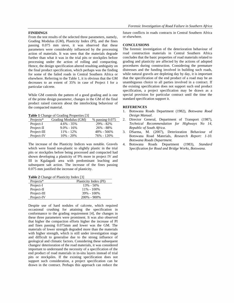
FINIDINGS From the test results of the selected three parameters, namely, Grading Modulus (GM), Plasticity Index (PI), and the fines passing 0.075 mm sieve, it was observed that these parameters were considerably influenced by the processing action of materials. It was seen that the materials degrade further than what it was in the trial pits or stockpiles before processing under the action of rolling and compacting. Hence, the design specification altered resulting ambiguity on the final product specification, which perhaps was the finding for some of the failed roads in Central Southern Africa or elsewhere. Referring to the Table 1, it is obvious that the GM decreases to an extent of 35% in case of Project I for a particular calcrete. While GM controls the pattern of a good grading and is one of the prime design parameter, changes in the GM of the final product raised concern about the interlocking behaviour of the compacted material. Table 1 Change of Grading Properties [3]
The increase of the Plasticity Indices was notable. Gravels which were found non-plastic to slightly plastic in the trial pits or stockpiles before being processed and compacted had shown developing a plasticity of 9% more in project IV and III in Kgalagadi area with predominant leaching and subsequent salt action. The increase of the fines passing 0.075 mm justified the increase of plasticity. Table 2 Change of Plasticity Index [3]
Despite use of hard nodules of calcrete, which required occasional crushing for attaining the specification in conformance to the grading requirement [4], the changes in these three parameters were prominent. It was also observed that higher the compaction efforts higher the increase of PI and fines passing 0.075mm and lower was the GM. The materials of lower strength degraded more than the materials with higher strength, which is still under investigation stage and difficult to generalise due to the strong influence of geological and climatic factors. Considering these subsequent changes/ deterioration of the road materials, it was considered important to understand the necessity of a specification of the end product of road materials in in-situ layers instead of trial pits or stockpiles. If the existing specification does not support such consideration, a project specification can be drawn in the contract. Perhaps this approach can reduce the
future conflicts in roads contracts in Central Southern Africa or elsewhere. CONCLUSIONS The forensic investigation of the deterioration behaviour of road construction materials in Central Southern Africa concludes that the basic properties of road materials related to grading and plasticity are affected by the actions of adopted procedures during construction. Considering the premature distresses and the funding involved in building such roads, while natural gravels are depleting day by day, it is important that the specification of the end product of a road may be an unambiguous choice to all parties involved in a contract. If the existing specification does not support such end product specification, a project specification may be drawn as a special provision for particular contract until the time the standard specification support it. REFERENCES 1. Botswana Roads Department (1982), Botswana Road
Design Manual. 2. Director General, Department of Transport (1987),
Technical Recommendation for Highways No 14, Republic of South Africa.
3. DSarma, M. (2007), Deterioration Behaviour of Botswana Road Materials, Research Report: 1-10. Botswana Roads Department.
4. Botswana Roads Department (1983), Standard Specification for Road and Bridge Works, Botswana.
Proceedings of Indian Geotechnical Conference December 13-15,2012, Delhi(Paper No. J1007)
LANDSLIDE INVESTIGATION AT KM 162, NH-39, - A CASE STUDY P.S. Prasad, Sr. Scientist, Central Road Research Institute, New Delhi, [email protected] Kishor Kumar, Sr. Pr. Scientist, Central Road Research Institute, New Delhi, [email protected] U.K.Guru Vittal, Head, Sr. Pr. Scientist, Central Road Research Institute, New Delhi, [email protected] Sudhir Mathur, Adviser, Chief Scientist, Central Road Research Institute, New Delhi, [email protected] Jai Bhagwan, Sr. Pr. Scientist, Central Road Research Institute, New Delhi, [email protected] Kanwar Singh, Sr. Scientist, Central Road Research Institute, New Delhi, [email protected] ABSTRACT: The National Highway 39 constitutes the life line of Nagaland and Manipur states and also an important highway from the point of view of its strategic location. The NH-39 in the stretch between km 162.00 in Nagaland and km 236.1 in Manipur experiences frequent landslides/debris flow at different locations which cause not only the disruptions to the traffic but also damages to the road infrastructure and agricultural land. One of the severely affected locations on NH – 39 at km 164 in the Nagaland state, which was experienced unprecedented subsidence and Debris flow phenomenon in 2008. The road has subsided by about 20 m at this location. This stretch was investigated and the slope stability analysis was carried out by GEO 5 software. The present paper highlights the outcome of the study along with design of suitable remedial measures for its prevention based on the detailed investigations. INTRODUCTION The National Highway 39 is the life line of Nagaland and Manipur state and also important from the point of view of its strategic location. The hills along NH-39 are very fragile and experience landslides and subsidence which have been active since inception of this road. Due to sinking and sliding of road along NH-39, particularly during monsoon period, traffic movement gets disrupted for months together. The hills of the Nagaland, like of other states of Northeastern region are made up of one of the youngest and geologically folded immature formations. The National Highway 39 route map with various landslide locations is shown in Fig 1. The slide at km 162 is classified as a compound landslide. Multi-directional tension cracks were observed all over the landslide area. The gabion walls constructed earlier on road side have sunk and distorted. The road has been subsided by 20m. GEOLOGY The geology of the area comprises of shale and sandstone beds occurring in alternation with their strike extending across the general slope of the area (Fig. 2). Sandstone is major in higher reaches of the area and shale is appearing mainly in the lower parts. The landslide area is composed of entirely shale. The rocks in the area are highly weathered with presence of large number of cracks and joints and large scale and small scale faults and thrusts. A major thrust with the distance of influence of several kilometers and extending NE-SW (along the slope of the area) is an important feature in the area. This shows that the area is tectonically active.
Fig. 1 NH 39 Route Map with Landslide Locations
Fig. 2 Geology Map of Landslide
P.S.Prasad, Dr. Kishor Kumar, U.K. Guru Vittal , Sudhir Mathur, Jaibhagwan & Kanwar Singh
GEOMORPHOLOGY For the convenience of the understanding the mechanism of the failure, morphology of the slope is described in two parts i.e., in uphill slope of slide and downhill slope of slide. Fig. 3 shows the geomorphology of the landslide area. In general the area has a rugged topography. Slope failure in this locality is in various forms such as, weathering, minor wedge failures, rock falls and mud flow make it a special complex failure representing almost every kind of failure. Part of National Highway has been subsided due to the movement of slope material. The load from above has resulted in deformation and collapse of gabion walls (Fig. 4). Severe gully erosion illustrates role of water in causing failure. Rocks are present in two conditions, viz. fresh and weathered. The shale rock behaves like mud due to oversaturation during rainy season causing differential movement on the slope as shown in Fig 5.
Fig. 3 Geomorphology of the slide
Fig. 4 Collapse of gabion wall
Above National Highway This failure area is an example of compound landslide. On the upper left flank of the landslide there are fields that are still being cultivated. By observing the rest of part, it appears
that cultivation was being done in recent past but has been stopped due to sprawling of the land.
Fig. 5 Saturation of shale causes mudflow
Surrounding area is immensely cultivated. Just above the National highway is a plain that may be referred to as vestige of the earlier cultivated field. The slope inside the landslide boundary is gentle that causes water to stay for longer duration thereby propping up the infiltration. Tension cracks are observed all over the landslide area and they show multi-directional orientations (Fig 6).
Fig. 6 Multi dimensional cracks on agricultural land The central portion of this vertical cut adjoining the road has clayey soil which is saturated. The rice field has extensive cracks and is depressed towards the uphill and raised near the road (Fig 4). Thus the entire slope which has failed comprise of many steps which are depressed towards the uphill and are elevated towards the toe. Two Nallahs are flanking the rice field. These Nallahs carry seepage and run-off water. However, the pipe culvert which had been constructed to carry the water from the Nallahs has been damaged. Hence the seepage water is percolating into the ground and surfacing again in the slope below the road
Landslide investigations at km 162, NH – 39, - A Case Study
Below National Highway The downhill side of the slide at km 162.50 (below the NH 39) is sparsely vegetated and devoid of farming activity. These cracks are multidirectional but majority of the cracks are seen to be parallel to the road alignment indicating that slope material is sliding away from the road (Fig. 7). There is thick vegetation along the boundary of the slide while vegetation is scarce on the slide area perhaps indicating recent/continuous movement of the slide material. The downhill slope of the slide typically comprises of weathered shale and the overburden soil is not very thick. It is hardly 30–50 cm in thickness, below which shale of medium strength was observed. On the LHS, an old road alignment which has slided down and has been abandoned (Fig 8). In both edges of the slide, seepage points were observed.
Fig. 7 Cracks adjacent to highway on downhill slope
Fig. 8 Abandoned subsided road on downhill slope
GEOTECHNICAL PROPERTIES OF SOIL From the road the soil samples are collected from the landslide area on uphill slope (agricultural field with huge cracks) and downhill slope (agricultural field) toe of the slide. The liquid limit of the soil is varies from 41% to 47% and PI is 15%. As per IS classification the soil is classified as CI.
The shear strength parameters c’ and Φ’ Values are 2 KPa and 230 respectively. STABILITY ANALYSIS The cross sections chosen for the stability analysis are shown in Fig.9. Stability analysis of the slope was carried out by GEO 5 software. The FOS of slope varies from 0.67(Saturated condition) to 1.78(Dry condition) at different locations under varying drainage conditions. The stability analysis clearly shows that the slope is stable in dry condition, but it is failing even when the slope is partially saturated.
Fig. 9 Cross Sections Considered for Stability Analysis PROBABLE CAUSES OF THE LANDSLIDE
1. Weak geological formation. 2. High rain fall. 3. High weathering and erosion. 4. Deforestation. 5. Inadequate drainage measures. 6. Inadequate protection measures. 7. Cohesive soil (silty clayey). 8. Quarrying and non-functional road. 9. Successive failures (uncontrolled). 10. Cultivation fields which are irrigated. 11. Very low strength of Shale rock beneath the road.
REMEDIAL MEASURES The gabion walls are constructed to stabilise the slope. But the existing gabion walls have settled due low bearing capacity of soil as shown in Fig 4. Design of existing gabion wall (Fig 10) and the proposed gabion wall (Fig 11) were analysed by GEO 5 software and the results are given below. Verification of the Existing Wall (Failed Gabion Wall): Check for overturning stability: Resisting moment Mres = 0.9* 151.57 = 136.41 kNm/m Overturning moment Movr = 141.36 kNm/m Wall for overturning is NOT ACCEPTABLE
P.S.Prasad, Dr. Kishor Kumar, U.K. Guru Vittal , Sudhir Mathur, Jaibhagwan & Kanwar Singh
Check for slip: Resisting lateral force Hres = 0.9* 51.18 = 46.07 kN/m Active lateral force Hact = 110.56 kN/m Wall for slip is NOT ACCEPTABLE
Fig. 10 Design of Existing Gabion Wall Bearing capacity of foundation soil check: Eccentricity of normal force e = 87.34 cm Maximum allowable eccentricity e,allow = 62.70 cm Eccentricity of the normal force is NOT ACCEPTABLE Stress at the footing bottom Sigma = 871.20 kPa Bearing capacity of foundation soil Rd = 100.00 kPa Bearing capacity of foundation soil is NOT ACCEPTABLE Overall check - ABUTMENT is NOT ACCEPTABLE
Fig. 11 Design of Proposed Gabion Wall Verification of the Proposed Gabion Wall: Check for overturning stability: Resisting moment Mres = 0.9* 151.57 = 136.41 kNm/m Overturning moment Movr = 21.25 kNm/m Wall for overturning is ACCEPTABLE Check for slip: Resisting lateral force Hres = 0.9* 53.68 = 48.31 kN/m Active lateral force Hact = 27.52 kN/m Wall for slip is ACCEPTABLE
Bearing capacity of foundation soil check: Eccentricity of normal force e = 0.00 cm Maximum allowable eccentricity e,allow = 62.70 cm Eccentricity of the normal force is ACCEPTABLE Stress at the footing bottom Sigma = 70.21 kPa Bearing capacity of foundation soil Rd = 100.00 kPa Bearing capacity of foundation soil is ACCEPTABLE Overall check - ABUTMENT is ACCEPTABLE CONCLUSIONS Seepage points were observed at the toe of the tilted gabion wall. The downhill slope is composed of multiple slides with seepage points and water ponding for agricultural purposes. Due to low bearing capacity in this area the gabion wall height should not be more than 4m. The gabions should be constructed with proper berms or by inclusion of reinforcement in the soil. The stability of the gabion wall was improved by inclusion of 4 layers of Geogrids or same gabion mesh extended in to the soil for a length of 3m. Catch water drains were also suggested for improving the existing drainage system. REFERENCES CRRI (2009), Report on “Investigation and Recommendation of suitable remedial measures at Landslide stretches on Dimapur- Kohima- Mao- Maran Road (NH 39)”Central Road Research Institute, New Delhi. ACKNOWLEDGEMENTS This Paper is published with the kind permission of Director, Central Road Research Institute. Authors are grateful to colleagues of Geotechnical Engineering Division, who contributed in the investigations and preparation of report. The authors are also thankful to BRO for sponsoring this project.
Proceedings of Indian Geotechnical Conference December 13-15,2012, Delhi (Paper No. J1008)
STABILITY OF DRAGLINE WASTE ROCK DUMP IN KHADIA OPENCAST COAL MINE
Avijit Dey, D.G.M. (Civil), M/s STEAG Energy Services (I) Pvt. Ltd., India, [email protected] Indrajit Roy, Professor-Civil Engineering Department, B.I.T., Mesra , India , [email protected]
ABSTRACT: India ranks third in world coal production mainly due to 89% contribution from opencast mining or surface mining. Coal India (a major coal producing organization in India) produced 431.27 million tonnes of coal in the year 2009-10 from opencast mining or surface mining technology. It is pertinent here to mention that to mine out 431.27 million ton-nes of coal from opencast mining, 695.29 million cubic.m of waste rock and soil was excavated in the year 2009-10. But a major hindrance in sustaining this level of coal production from open cast mining is area of land involved. Land require-ment due to opencast coal mining in India has been estimated to reach 2925 square km by 2025 (including 730 square km of forest cover) as against the present coverage of 1470 square km. It is also estimated that 0.85 million people will be dis-placed by the opencast coal mining projects by the year 2025 and would require to- be suitably re-located. This socio-environmental predicament requires a solution and the only possible way to reduce the area of land affected is to increase the slope angle of the waste dump embankments. However, this solution creates another problem in itself i.e. the stability of the waste rock dump. It is considered as one of the major issues faced in the open cast coal mining operation due to slope failures resulting in fatal accidents in some of the large opencast mines of India. In Indian opencast mining scenario, drag-line operated opencast mines with a share of 45% of total opencast coal production are considered to be the most efficient way of winning coal for opencast mines linked to power plants. However, the method of dragline operation involving ex-cavation and simultaneous back-filling is associated with concurrent problems of slope stability of waste rock dumps formed by dragline. The difficulty in handling waste rock dumps in dragline operation is discussed in this paper through a case study of Khadia opencast coal mine located in Singrauli coalfield ,UP.
INTRODUCTON Surface mining operation often result in removal of huge quantities of waste material and subsequently dumping it outside quarry areas or back filling in excavated areas as the case may be. In recent years the unprecedented in-crease in rate of accumulation of waste dump has been great environmental concern because it leads more fre-quent failure of dump. General increase in environmen-tal awareness has given rise to concern about safe and economic design of waste dump. On the one hand stable slope are essential for safety of man and machine and other hand huge amount of land and money can be saved by optimizing slope geometry of dump. It is therefore a technical and economic necessity that the more efficient compromise can be achieved, in light of these two con-flicting requirement, by optimizing the slope that is steep enough to economically acceptable and flat enough .to safe. In past years there are some example came in the existence which created a tragic and painful incident for mankind.To prevent such type of incident this present study and analysis of stability slopes have been done by limit equilibrium methods. GEO-MINING CONDITION The Khadia block is located in the south-central part of the Moher-sub basin of Singrauli coalfield bounded by the Dudhichua Project in the east and the Nigahi project in the west. The rocks of Barakar formation are exposed in this block along with recent soil I alluvium cover. Predominant rock type of Barakar formation is sandstone followed by shale. The sandstone is grey to dirty white in color.
SAMPLE COLLECTION AND TESTING The rock sample are taken at different height of dump mass, and collected in plastic cement bags. At the same time other information are taken like height of dump, lo-cation of water table, face angle, and type of dumper working over there. Around 150 kg broken sample of dragline dump and 150 kg crushed rock sample from in-terface material were collected and transported to B.IT. Mesra laboratory for preventive measures.
Width of the corridor at dragline sitting level is not less than 15 metres in any case.
Dragline sitting level
Fig. 1 Failure of Dump leading to fatality
Avijit Dey, Indrajit Roy, �
Fig. 2 Failure surface after dump slide as observed after removal of debris from failed dump mass
In B.I.T Mesra, a separate computer controlled large scale shear box test machine have installed in which the sample have been tested at different degree of saturation for calculating the value of cohesion (c) and angle of in-ternal friction (Φ).
Fig. 3 Laboratory test result
FORMULATION OF THE STUDY Stability of dragline dump deals with geo-technical characteristics of both dump material and interface material (i.e. slushy material lying at the floor of the dragline dump). The dump material is comprised of both excavated black-cotton soil mass and fragmented argillaceous sandstone with clay rock in natural moisture condition, whereas interface material is comprised of both black-cotton soil and waste argillaceous sandstone in fragmented condition submerged under water. The dump and interface material has been tested in large box shear (40cm by 40cm) at the laboratory. Other than laboratory tested values, back analysis has been carried on the existing dragline dump (which is standing at limiting equilibrium) considering that the dump is standing at factor of safety equal to one. The dump and interface material is found to have high plas-ticity index (35.37%) with majority of Montmorillonite
minerals which absorbs water, leading to expansion in volumes and abrupt reduction of shear strength proper-ties. As per hydro-geological study of this area, there is a steady seepage of water from nearby river during rainy season. Oozing of water to the length of (Pa= 7 m) is found to emerge from toe of dragline dump in rainy sea-son. Because a number of spoil dumps from successive strips had shown large instability in recent years in this mine, it was important to carry out a thorough geo-technical in-vestigation with stability analysis of the existing spoil dumps so that future dump formation would not initiate further slope instability.
Stability Analysis In this investigation , a comparative study of Factor of Safety under different method has been carried out using computer program through M/S Excel Spread sheet. The Factor of safety has been executed under Seismic and Non-seismic condition. These Excel spread sheets are based on
o Fellenious Method o Bishop’s Simplified Method o Spencer’s Method
Design Profile for the Analysis i) Slope angle between dragline sitting level and the peak of dragline dump should not be steeper than 36 degree with respect to horizontal. ii) Height of dragline dump with respect to mine floor should not exceed 79m for above rec-ommended slope angle whereas height of dump with respect to horizontal plane passing through toe of the dump will not exceed 85m. iii) Length of Oozing is 3m and height of water is 17m at a distance 60m from the start of the slope. iv) Cohesion of dump material is 45 kN/m2. Angle of internal friction of dump material is30 degree. v) Cohesion of interface material is 58 kN/ m2 vi) Angle of internal friction of interface materi-al is 29 degree. vii) Bulk Unit weight is 18.3 kN/ m3
Slip Surface and Slices
The design dump profile has been analysed under fifty different trial slip surfaces. Both circular and circular-cum-planner slip surfaces has been considered in the analysis. In Figure (4.3) a sample circular-cum-planner slip surface over designed dump profile has been shown. The angle β1 and β2 are called Directional angle and it depends on Slope angle. In our consideration of slope angle 360 , the Directional angle β1 is 260 and β2 is 350
Proceedings of Indian Geotechnical Conference December 13-15,2012, Delhi (Paper No. J1008)
Fig. 4 Slip Circle formation
Co-ordinate origin (0,0) is considered at the start of the slope as shown in fig. 4.1. The line joining the intersec-tion on directional lines and coordinate (-H, 4.5H) has been extended further on which the centre of Slip basic circles are considered. This centers are marked as 1,2,3 etc. described in fig. 4.1. The total angle (3600) about a point is divided into equal ten division of each measur-ing angle 360. Further slip circles are considered on this lines as descript in the fig. 4 above. For an assumed section, a trial failure surface is consid-ered by arbitrarily selecting the centre of first iteration method and the block of soil mass under the circle has been divided into fifty numbers of slices of equal thick-ness. Each slice is subjected to its own weight and other forces like seepage force due to ground water table and rain water and dynamic force on dump due to blasting in the nearest quarry face. All these forces acting on each slice are resolved into the components to determine dis-turbing and frictional forces on individual slice. They are suitably added for all slices respectively to determine the cumulative disturbing and frictional forces acting on the entire trial surface selected. Cohesive resistance of the whole failure surface is calculated and added to the cu-mulative resisting force. The ratio of the cumulative re-sisting force to the cumulative disturbing force is the Factor of Safety of the selected trial surface. The process is repeated by selecting in a systematic manner several trial surfaces around the first one to find the absolute minimum Factor of Safety (F.O.S.), for the particular combination of the face angle and height of the dump
FACTOR OF SAFETY All the recommended Factor of safety suggested by different agencies such as “National coal board ,U.K, United States D’ Appolonia consulting engineers, Mines branch Canada, Stability of pit slopes and dumps by G.L. Fiesenko, Russia for surface mine slope de-sign are considered. A factor of safety of more than 1.10 is envisaged here for the design which considers maximum
seismic acceleration and also a factor of safety of more than 1.20 is envisaged here
Table-1,Tabulated Factor of Safety By
Fellinious By
Bish-op
By Spen-
cer
Recom-mend by NCBUK
Without seismicity
1.173 1.207 1.190 1.200
With seismicity
1.158 1.188 1.178 1.100
The FOS calculated by Fellenious method is under rated as it does not consider the effect of inter-slice forces. Thus the design FOS would be governed by the mini-mum value obtained from Bishop and Spencer method. The minimum FOS obtained without effect of seismicity is 1.190, and The minimum FOS obtained with effect of seismicity is 1.178
RECOMMENDED DUMP PROFILE
Fig. 5 Recommended Dump Profile
For monitoring such profile, following measures are un-dertaken i) Height of dragline dump is restricted to 80m ii) Overall slope angle of dragline dump is not steeper
than 380 iii) Two corridors at dragline sitting level of not less
than 15m and another at coal rib level of not less than 10m is maintained.
iv) Embankment is provided at the toe of the dump and at the outer edge of the coal roof corridor to ar-rest any rolling boulder from the slope.
v) Floor gradient of the coal seam is maintained such as to ensure consistent natural gravitational flow of water towards sump.
vi) The design process necessary involves personnel who are engaged in day to day operation and while operation there must not be any deviation from de-signed parameters. A process of regular auditing is
Avijit Dey, Indrajit Roy, �
put in operation to design and operate the mine in correct manner.
vii) Efforts are made to mine out coal without leaving a coal rib. Even if a coal rib is left against the toe of the dump, it is of dimensions arrived at through proper scientific studies.
viii) No low bearing capacity soil is allowed to be dumped on the floor of de-coaled area so as to form the base of the dump.
ix) Top soil is dumped separately as far as possible much away from the site of active internal dump-ing.
x) No top soil is allowed to be dumped on the floor of de-coaled area to form the base of dragline dump.
xi) Toe of shovel-dumper dump is formed at least 120 to 150m away (i.e. two cuts) from the toe of Drag-line dump so that dragline dump gets adequate time to stabilize before fresh dumping by Dumper.
xii) Dump monitoring Cell has been established headed by senior mining Engineer and assisted by survey-ors to monitor the dumps
xiii) All dragline dumps are designed for a Factor of safety in excess of 1.1 considering seismic forces and 1.2 without considering dynamic forces i.e. seismic force and blast vibration force.
REFERENCES 1. Central Mine Planning and Design Institute, India. (2008) “ Operational Plan of Sasti Opencast Project - Ranchi, India”. Consultancy report by Central Mine Planning and Design Institute Ranchi, India. 2. Roy, I. (2009) “Investigation Report on Causes and Remedies of Accident in the Sasti Opencast Project of Western Coalfield Limited”. Consultancy report by Central Mine Planning and Design Institute Ranchi, India. 3. Roy, I. (2005) “Slope Stability Study of Sasti Open cast Project”. Consultancy report by Central Mine Planning and Design Institute Ranchi, India. 4. Roy, I. (1998) “Influence of Geo-Engineering Parame ters on the Stability of Dumps, Ph.D Thesis, Indian In stitute of Technology, Kharagpur”. 5. Murthy, V.N.S, Principles of Soil Mechanics and Foundation Engineering, Fifth Edition, UBS Publish er's Ltd, 2001. 6. Baker, R. (1980) "Determination of the critical slip surface in slope stability computations," International Journal for Numerical and Analytical Methods in Geomechanics, Vol. 4, No.4, pp. 333-359. 7. Bellman, R. (1957) "Dynamic Programming, Prince ton," Princeton university press, Princeton, New Jer sey, USA.
8. Spencer, E. (1967) "A method of analysis of the sta bility of embankments assuming parallel inter-slice forces," Geotechnique, Vol. 17, No.1, pp. 11-26. 9. Nguyen, M. (1985) "Determination of critical slope failure surfaces," Journal of Geotechnical Engineer ing, ASCE, Vol. 111, pp. 238. 10. Spendley, N., G. Hext and F. Himsworth (1962) "Sequential application of simplex design in opera tions and evolutionary operations," Technometrics, Vol. 14, No.4, pp. 441-459.