Learning Holiday Lights Team Number 10 Client Dr. Daniels Adviser Dr. Daniels Team Members/Roles Steven Williams/Hardware Lead Jake Grace/Software Lead Joseph Nunez/Meeting Scribe Valery Smith/Signal Processing Specialist Thien Nguyen/Webmaster Chad Griggs/Report Manager Team Email [email protected]Team Website sddec19-10.sd.ece.iastate.edu
Transcript
Learning Holiday Lights Team Number 10
Client
Dr. Daniels
Adviser Dr. Daniels
Team Members/Roles
Steven Williams/Hardware Lead Jake Grace/Software Lead
Joseph Nunez/Meeting Scribe Valery Smith/Signal Processing Specialist
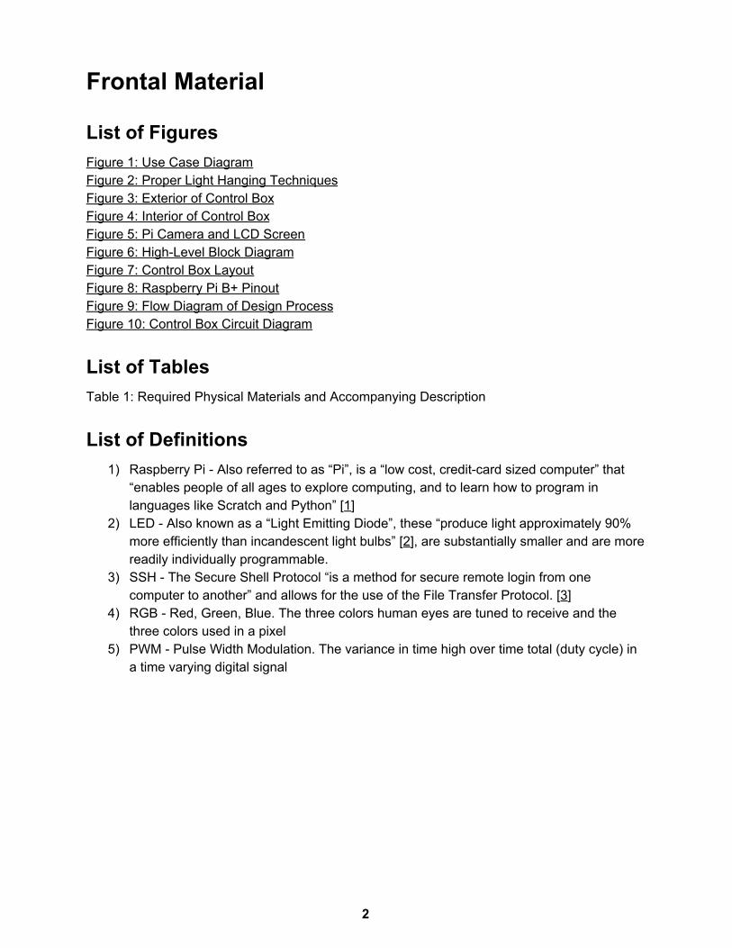
List of Figures Figure 1: Use Case Diagram Figure 2: Proper Light Hanging Techniques Figure 3: Exterior of Control Box Figure 4: Interior of Control Box Figure 5: Pi Camera and LCD Screen Figure 6: High-Level Block Diagram Figure 7: Control Box Layout Figure 8: Raspberry Pi B+ Pinout Figure 9: Flow Diagram of Design Process Figure 10: Control Box Circuit Diagram
List of Tables Table 1: Required Physical Materials and Accompanying Description
List of Definitions 1) Raspberry Pi - Also referred to as “Pi”, is a “low cost, credit-card sized computer” that
“enables people of all ages to explore computing, and to learn how to program in languages like Scratch and Python” [1]
2) LED - Also known as a “Light Emitting Diode”, these “produce light approximately 90% more efficiently than incandescent light bulbs” [2], are substantially smaller and are more readily individually programmable.
3) SSH - The Secure Shell Protocol “is a method for secure remote login from one computer to another” and allows for the use of the File Transfer Protocol. [3]
4) RGB - Red, Green, Blue. The three colors human eyes are tuned to receive and the three colors used in a pixel
5) PWM - Pulse Width Modulation. The variance in time high over time total (duty cycle) in a time varying digital signal
2
1 Introduction
1.1 Acknowledgement We would like to acknowledge Dr. Tom Daniels for his time and expertise with this
project, as well as the previous senior design group for laying a foundation onto which we can build our design.
1.2 Problem and Project Statement During the holiday season it’s tradition to put on interesting light displays to impress
family and neighbors. Legacy methods of using static lights on trees or outdoor areas such as roofs or bushes have been superseded by more modern technologies. In 2019, we at Team 10 want to take the holiday season to the next level! The idea is to take boring static light strips and make them magical with dynamic patterns and more. With our product, you will be able to set up the lights on any object of your choosing and make breathtaking visual effects.
Our proposed solution is to take the system created by the previous senior design group and improve it in a few ways. Instead of a single Raspberry Pi and a phone app, we are going to use 2 Pis. The first will host the server and issue commands to the light system. The second will have a camera connected to it to perform the image processing and calibration.
1.3 Operational Environment The system should function in both outdoor and indoor environments, regardless of any
background image noise such as reflecting windows. This means the enclosure for the Raspberry Pi and power distribution must be rugged enough to handle snowy or rainy weather without the electronics being damaged. This system could be set up in many different conditions. Therefore, we will need to test the calibration in different lighting conditions and give the user some lighting guidelines for best results.
3
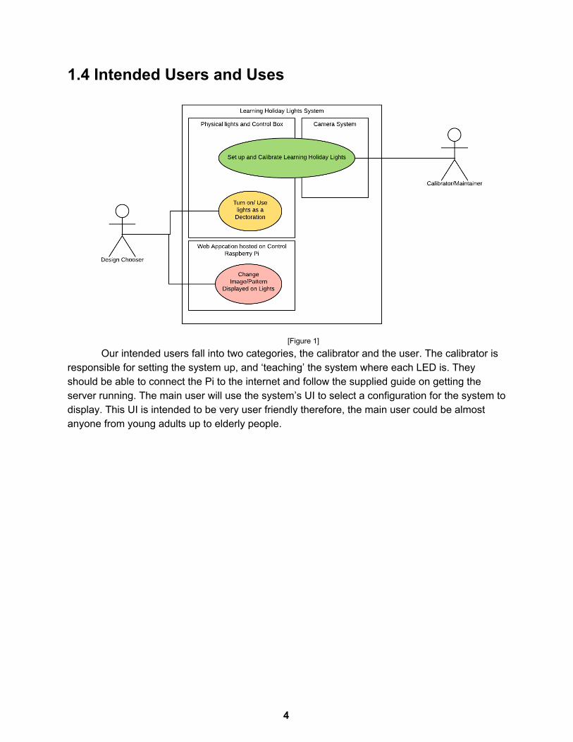
1.4 Intended Users and Uses
[Figure 1]
Our intended users fall into two categories, the calibrator and the user. The calibrator is responsible for setting the system up, and ‘teaching’ the system where each LED is. They should be able to connect the Pi to the internet and follow the supplied guide on getting the server running. The main user will use the system’s UI to select a configuration for the system to display. This UI is intended to be very user friendly therefore, the main user could be almost anyone from young adults up to elderly people.
4
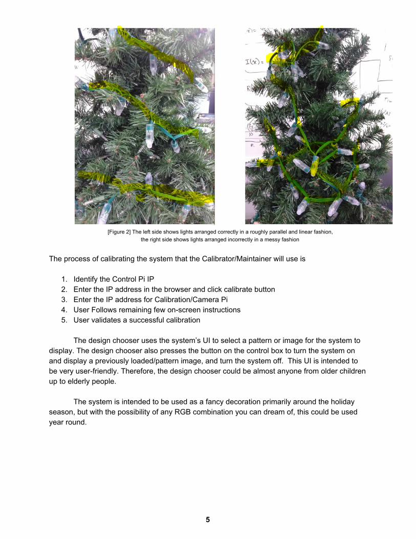
[Figure 2] The left side shows lights arranged correctly in a roughly parallel and linear fashion, the right side shows lights arranged incorrectly in a messy fashion
The process of calibrating the system that the Calibrator/Maintainer will use is
1. Identify the Control Pi IP 2. Enter the IP address in the browser and click calibrate button 3. Enter the IP address for Calibration/Camera Pi 4. User Follows remaining few on-screen instructions 5. User validates a successful calibration
The design chooser uses the system’s UI to select a pattern or image for the system to
display. The design chooser also presses the button on the control box to turn the system on and display a previously loaded/pattern image, and turn the system off. This UI is intended to be very user-friendly. Therefore, the design chooser could be almost anyone from older children up to elderly people.
The system is intended to be used as a fancy decoration primarily around the holiday
season, but with the possibility of any RGB combination you can dream of, this could be used year round.
5
1.5 Assumptions and Limitations Assumptions:
● The user has a working WiFi internet connection in accordance with the IEEE 802.11 standards for media access control and physical layer protocol for implementing WiFi.
● The user has electricity. ● The user has ample space to safely store the system.
Limitations: ● We have a string of lights that we are expected to use. ● The speed of the system will be limited by how fast each component can communicate
with each other. ● There will be a limit to how fast the image processing takes to complete. ● The system should not pose any safety concerns.
1.6 Expected End Product and Deliverables
User Interface - The user interface will be a user-friendly web application hosted on the control Raspberry Pi using Apache http/PHP/Python. Having it be a web-app allows the user to access it from any device with an internet browser of their choosing. We will use websockets to have the server push events to the control Raspberry Pi to control the lights. On the user interface the user can either upload images files to be texture mapped to the LEDs on the tree or design a basic pattern to be displayed such as a rotating rainbow or other select colors.
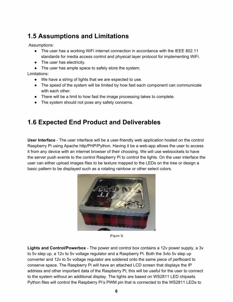
[Figure 3]
Lights and Control/Powerbox - The power and control box contains a 12v power supply, a 3v to 5v step up, a 12v to 5v voltage regulator and a Raspberry Pi. Both the 3vto 5v step up converter and 12v to 5v voltage regulator are soldered onto the same piece of perfboard to conserve space. The Raspberry Pi will have an attached LCD screen that displays the IP address and other important data of the Raspberry Pi; this will be useful for the user to connect to the system without an additional display. The lights are based on WS2811 LED chipsets. Python files will control the Raspberry Pi’s PWM pin that is connected to the WS2811 LEDs to
6
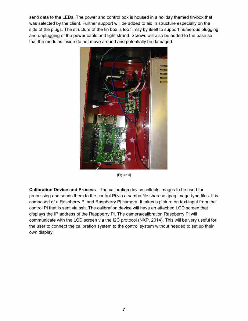
send data to the LEDs. The power and control box is housed in a holiday themed tin-box that was selected by the client. Further support will be added to aid in structure especially on the side of the plugs. The structure of the tin box is too flimsy by itself to support numerous plugging and unplugging of the power cable and light strand. Screws will also be added to the base so that the modules inside do not move around and potentially be damaged.
[Figure 4]
Calibration Device and Process - The calibration device collects images to be used for processing and sends them to the control Pi via a samba file share as jpeg image-type files. It is composed of a Raspberry Pi and Raspberry Pi camera. It takes a picture on text input from the control Pi that is sent via ssh. The calibration device will have an attached LCD screen that displays the IP address of the Raspberry Pi. The camera/calibration Raspberry Pi will communicate with the LCD screen via the I2C protocol (NXP, 2014). This will be very useful for the user to connect the calibration system to the control system without needed to set up their own display.
7
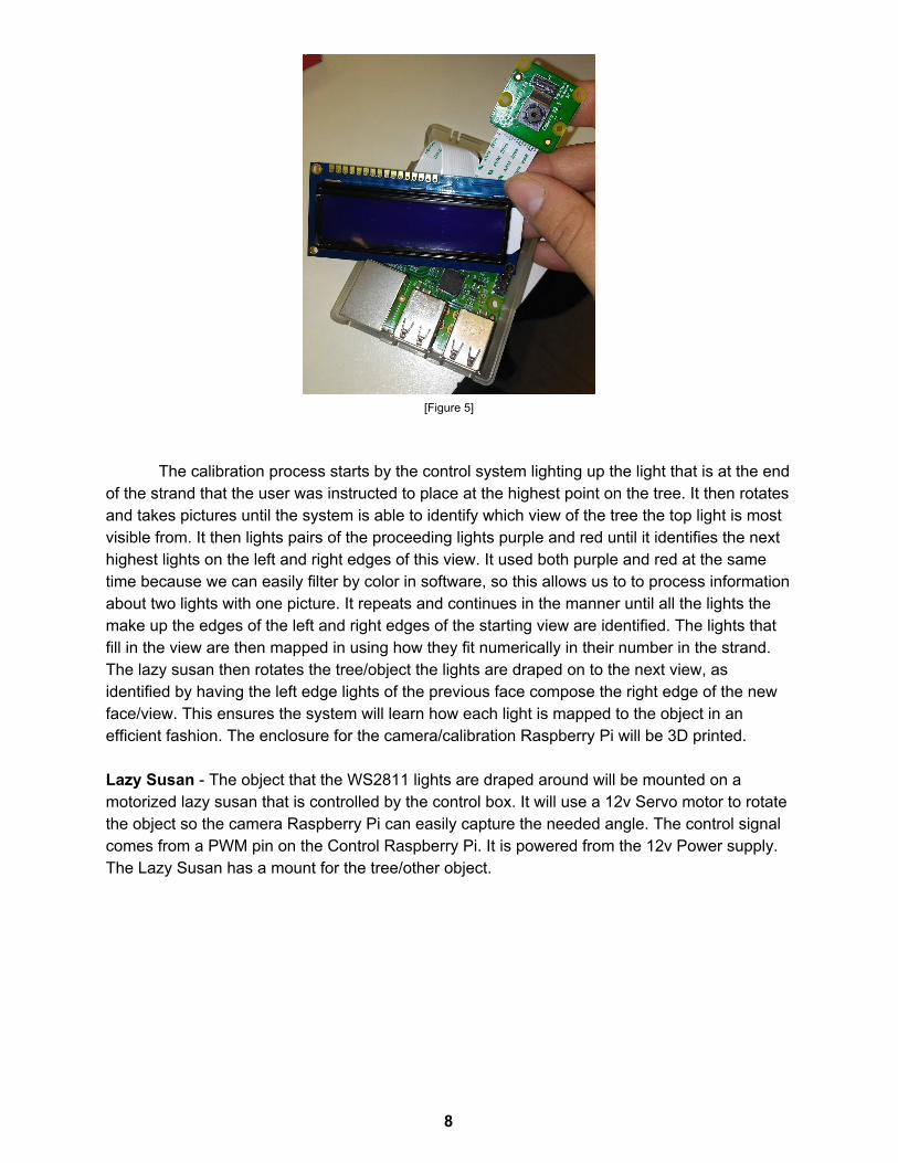
[Figure 5]
The calibration process starts by the control system lighting up the light that is at the end of the strand that the user was instructed to place at the highest point on the tree. It then rotates and takes pictures until the system is able to identify which view of the tree the top light is most visible from. It then lights pairs of the proceeding lights purple and red until it identifies the next highest lights on the left and right edges of this view. It used both purple and red at the same time because we can easily filter by color in software, so this allows us to to process information about two lights with one picture. It repeats and continues in the manner until all the lights the make up the edges of the left and right edges of the starting view are identified. The lights that fill in the view are then mapped in using how they fit numerically in their number in the strand. The lazy susan then rotates the tree/object the lights are draped on to the next view, as identified by having the left edge lights of the previous face compose the right edge of the new face/view. This ensures the system will learn how each light is mapped to the object in an efficient fashion. The enclosure for the camera/calibration Raspberry Pi will be 3D printed. Lazy Susan - The object that the WS2811 lights are draped around will be mounted on a motorized lazy susan that is controlled by the control box. It will use a 12v Servo motor to rotate the object so the camera Raspberry Pi can easily capture the needed angle. The control signal comes from a PWM pin on the Control Raspberry Pi. It is powered from the 12v Power supply. The Lazy Susan has a mount for the tree/other object.
8
2. Specifications and Analysis
[Figure 6]
2.1 Proposed Design
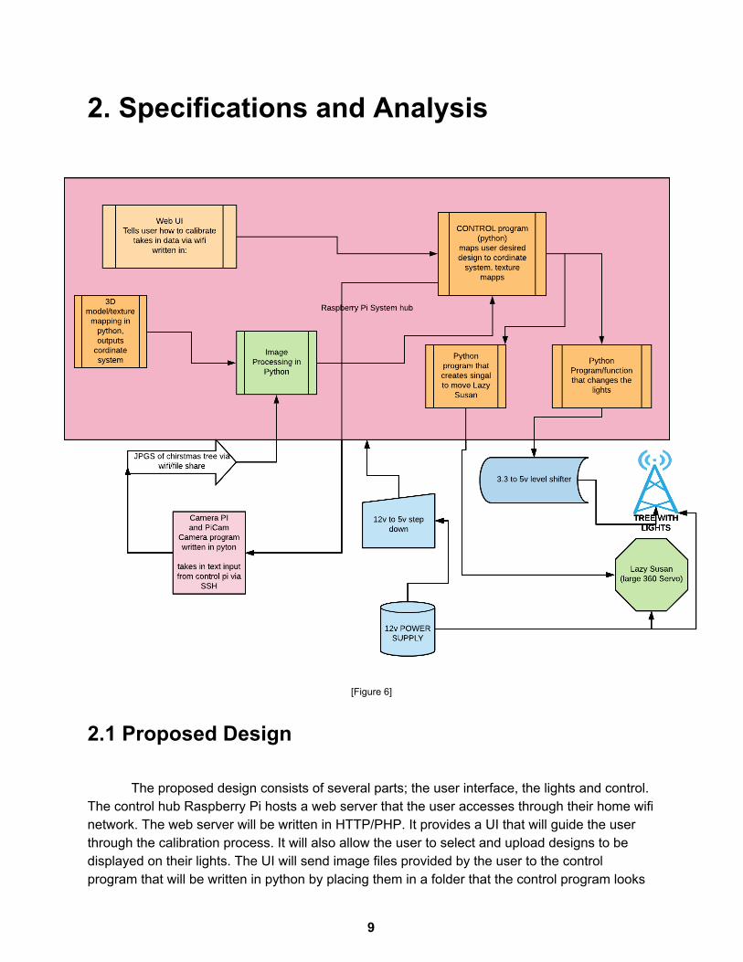
The proposed design consists of several parts; the user interface, the lights and control. The control hub Raspberry Pi hosts a web server that the user accesses through their home wifi network. The web server will be written in HTTP/PHP. It provides a UI that will guide the user through the calibration process. It will also allow the user to select and upload designs to be displayed on their lights. The UI will send image files provided by the user to the control program that will be written in python by placing them in a folder that the control program looks
9
in. The control program texture maps the input image files to the coordinate system that was generated by the calibration image processing and 3D map generation python programs.
The image processing program functions by using the OpenCV library to process images taken by the Camera Pi. It first calls the lightChange function to turn on the last 2 lights in the strip, one purple, one red. [8] Two separate colors are used because each color can easily be filtered and seen separate from each other. Then the image processing function is able to determine where the top row of this side of the tree is. If the lights are not visible to the camera the lazy susan program turns the tree until they are. The image processing function then progressively turns on pairs of lights until the 2nd from top row within that view are found. This is done until every light in that view is located. The lazy susan then rotates the tree for the rest of the sides/views. This manner will find the location of all the lights with respect to the tree. The 3D mapping function will then take in the dimensions of the tree and generate a conical coordinate system on which to plot the lights.
The camera portion is hosted on a Raspberry Pi which will be referred to as the camera pi. This is separate from the main Raspberry Pi which is referred to as the control pi. It is powered via a 5V AC plug. This is necessary because the camera has to be approximately 10 feet from the tree in order to capture the full height of the tree. A python program will commence by snapping a picture from the piCamera whenever either the user presses a button on the camera or the program receives a space character as an input trigger to take a picture. The pictures are stored on the camera Raspberry Pi where the system Pi can access them, through the shared file system.
The server is hosted using Apache httpd/PHP/Python. The web server will handle any requests sent by the user and process all image data submitted by the user for displaying on the tree. It does this by serving an interactive html page and storing the data sent by the user.
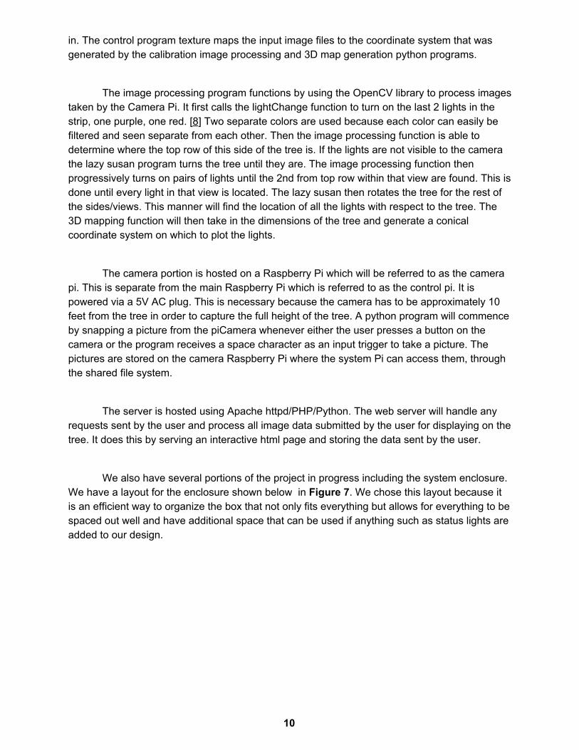
We also have several portions of the project in progress including the system enclosure. We have a layout for the enclosure shown below in Figure 7. We chose this layout because it is an efficient way to organize the box that not only fits everything but allows for everything to be spaced out well and have additional space that can be used if anything such as status lights are added to our design.
10
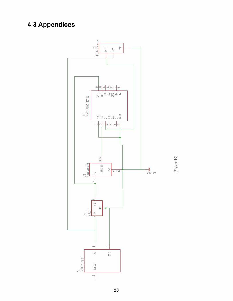
[Figure 7]
The power circuits for the Lights and control Raspberry Pi have been designed and implemented. The are shown in Figure 10 located in the appendices. The circuit consists of a LM7805 that is used to step down the 12V from the power supply to the 5V needed to power the Raspberry Pi. It also includes a SN74AHCT125 logic converter that is used to step the 3.3V PWM signal from pin 12 on the Raspberry Pi to 5V which is required by the WS2811 chip in the LEDs for data. We chose these circuits because they are efficient and simple with low numbers of ICs. This allows for more space in the box, less issue with perfboard space, and possibility of error when assembling. These circuits accomplish their tasks of stepping down the 12v to 5v and 3.3v to 5v level-shifting.In the future the power circuit will also responsible for powering the 12V servo that will be used to rotate the lazy susan. The whole system is powered by a 12V 30A power supply.
- The control box will be powered using an IEC 320 C14 standard power connector. - The two raspberry Pis will communicate using http requests. They will follow the JSON
standard specification. [11] - The control Raspberry Pi will communicate with the user’s device using IEEE standard
802.11, wifi [5]
2.2 Design Analysis From our design, we’ve implemented a few parts including the server, camera, and the
Control Pi. Although these parts are seemingly finished, we need to integrate them together in-order to fully test the system. However, each part has been individually tested. Working further, we need to finish the web application for full control of the lights as well as manual configuration. This will allow us to test the 3d mapping of the patterns/designs for the lights before the full image recognition calibration is online.
A potential drawback of using the LM7805 is that it is limited to 1.5A output current. We
are currently investigating whether this is preventing the control Raspberry Pi from operating normally. Within the datasheet there are application notes detailing a circuit to increase the
11
maximum output allowed by the voltage regulator. This design decision will be verified through testing.
In terms of strengths, we are looking at an entirely hands off approach for the calibration of this light system. This allows the user to set up the camera, click a button, and sit back while the lights auto-calibrate based on position. A second key strength is the two Pi system we are integrating into our solution. This allows us to set up a Pi for image recognition and one for the Control of the lights, therefore removing much of the setup for the User. This also solves a problem the previous group may have ran into when using a phone app. We will not need to do any maintenance or deal with compatibility issues an app may run into. The system will also run on a local wifi signal which means it doesn’t rely on an external server that may go down.
Although this system has a lot of strengths, we also see some areas of weakness. Firstly, the image recognition and auto-calibration is untested which means we don’t know for certain at this time if the image calibration will work, if it will be fast enough, and if the single Pi can handle to computational work. Secondly, the system needs to be intuitive and easy to set-up. This requires the system to be able to work in many different scenarios and can’t rely on the user setting the system up perfectly each time.
2.3 Standards 1. IEEE 802.11 - Standard for Wi-Fi communication over 2.4, 5, and 60 GHz frequencies.
The calibration Pi, control Pi, and user’s device all communicate with each other using devices that conform to this standard.
2. IEEE Light emitting diode safety and safety standards. Our system needs to be safe for all users, LEDs can cause damage to eyesight, and other bodily harm if used improperly.
3. IEC 60320 - Standard for power supplies not exceeding 250V Power supplies can easily cause fire or overheating if not complying with this standard.
3 Testing and Implementation
3.1 Interface Specifications
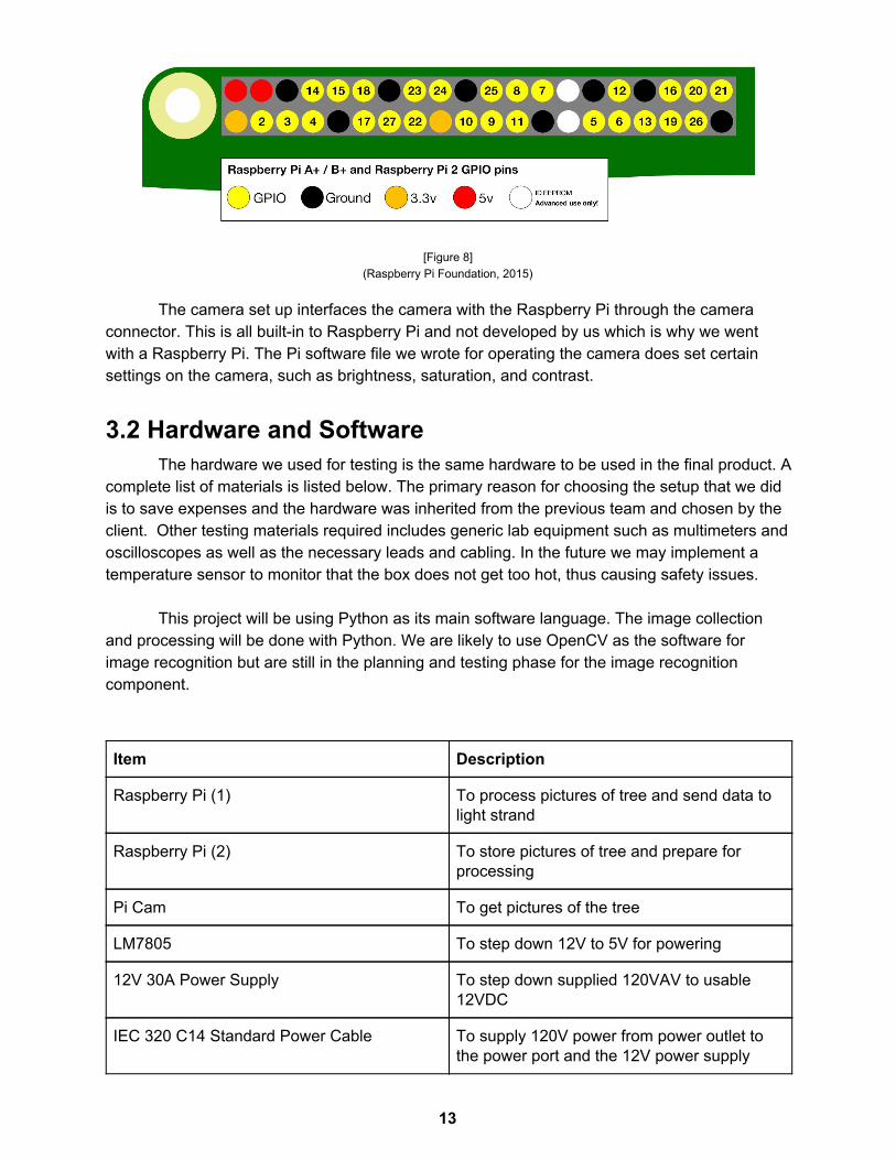
The hardware and software interface through the Raspberry Pi pins. The power system connects to the Raspberry Pi ground and 5v pins. Having a common ground is needed because voltage is relative, so the ground needs to be be consistent so the receiver (power distribution system/5v regulator circuit) sees the same voltage across the ground and 5v connections as the Pi so the Pi can be powered, and the same thing for the data signal on the Pi and the 3v:5v level shifter circuit.
The lightControl python file defines on which Raspberry Pi pin to output the signal. We are using pin 18.
12
[Figure 8] (Raspberry Pi Foundation, 2015)
The camera set up interfaces the camera with the Raspberry Pi through the camera connector. This is all built-in to Raspberry Pi and not developed by us which is why we went with a Raspberry Pi. The Pi software file we wrote for operating the camera does set certain settings on the camera, such as brightness, saturation, and contrast.
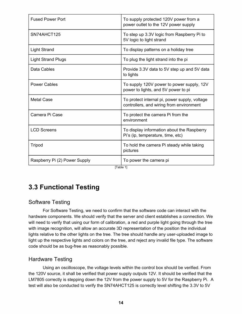
3.2 Hardware and Software The hardware we used for testing is the same hardware to be used in the final product. A
complete list of materials is listed below. The primary reason for choosing the setup that we did is to save expenses and the hardware was inherited from the previous team and chosen by the client. Other testing materials required includes generic lab equipment such as multimeters and oscilloscopes as well as the necessary leads and cabling. In the future we may implement a temperature sensor to monitor that the box does not get too hot, thus causing safety issues.
This project will be using Python as its main software language. The image collection
and processing will be done with Python. We are likely to use OpenCV as the software for image recognition but are still in the planning and testing phase for the image recognition component.
Item Description
Raspberry Pi (1) To process pictures of tree and send data to light strand
Raspberry Pi (2) To store pictures of tree and prepare for processing
Pi Cam To get pictures of the tree
LM7805 To step down 12V to 5V for powering
12V 30A Power Supply To step down supplied 120VAV to usable 12VDC
IEC 320 C14 Standard Power Cable To supply 120V power from power outlet to the power port and the 12V power supply
13
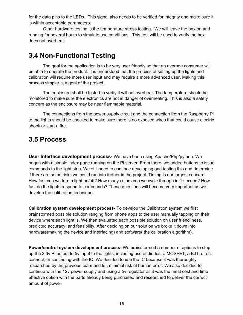
Fused Power Port To supply protected 120V power from a power outlet to the 12V power supply
SN74AHCT125 To step up 3.3V logic from Raspberry Pi to 5V logic to light strand
Light Strand To display patterns on a holiday tree
Light Strand Plugs To plug the light strand into the pi
Data Cables Provide 3.3V data to 5V step up and 5V data to lights
Power Cables To supply 120V power to power supply, 12V power to lights, and 5V power to pi
Metal Case To protect internal pi, power supply, voltage controllers, and wiring from environment
Camera Pi Case To protect the camera Pi from the environment
LCD Screens To display information about the Raspberry Pi’s (ip, temperature, time, etc)
Tripod To hold the camera Pi steady while taking pictures
Raspberry Pi (2) Power Supply To power the camera pi [Table 1]
3.3 Functional Testing
Software Testing For Software Testing, we need to confirm that the software code can interact with the
hardware components. We should verify that the server and client establishes a connection. We will need to verify that using our form of calibration, a red and purple light going through the tree with image recognition, will allow an accurate 3D representation of the position the individual lights relative to the other lights on the tree. The tree should handle any user-uploaded image to light up the respective lights and colors on the tree, and reject any invalid file type. The software code should be as bug-free as reasonably possible.
Hardware Testing Using an oscilloscope, the voltage levels within the control box should be verified. From
the 120V source, it shall be verified that power supply outputs 12V. It should be verified that the LM7805 correctly is stepping down the 12V from the power supply to 5V for the Raspberry Pi. A test will also be conducted to verify the SN74AHCT125 is correctly level shifting the 3.3V to 5V
14
for the data pins to the LEDs. This signal also needs to be verified for integrity and make sure it is within acceptable parameters.
Other hardware testing is the temperature stress testing. We will leave the box on and running for several hours to simulate use conditions. This test will be used to verify the box does not overheat.
3.4 Non-Functional Testing The goal for the application is to be very user friendly so that an average consumer will
be able to operate the product. It is understood that the process of setting up the lights and calibration will require more user input and may require a more advanced user. Making this process simpler is a goal of the project.
The enclosure shall be tested to verify it will not overheat. The temperature should be monitored to make sure the electronics are not in danger of overheating. This is also a safety concern as the enclosure may be near flammable material.
The connections from the power supply circuit and the connection from the Raspberry Pi to the lights should be checked to make sure there is no exposed wires that could cause electric shock or start a fire.
3.5 Process User Interface development process- We have been using Apache/Php/python. We began with a simple index page running on the Pi server. From there, we added buttons to issue commands to the light strip. We still need to continue developing and testing this and determine if there are some risks we could run into further in the project. Timing is our largest concern. How fast can we turn a light on/off? How many colors can we cycle through in 1 second? How fast do the lights respond to commands? These questions will become very important as we develop the calibration technique.
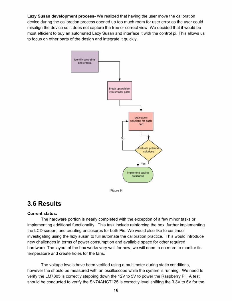
Calibration system development process- To develop the Calibration system we first brainstormed possible solution ranging from phone apps to the user manually tapping on their device where each light is. We then evaluated each possible solution on user friendliness, predicted accuracy, and feasibility. After deciding on our solution we broke it down into hardware(making the device and interfacing) and software( the calibration algorithm).
Power/control system development process- We brainstormed a number of options to step up the 3.3v Pi output to 5v input to the lights, including use of diodes, a MOSFET, a BJT, direct connect, or continuing with the IC. We decided to use the IC because it was thoroughly researched by the previous team and left minimal risk of human error. We also decided to continue with the 12v power supply and using a 5v regulator as it was the most cost and time effective option with the parts already being purchased and researched to deliver the correct amount of power.
15
Lazy Susan development process- We realized that having the user move the calibration device during the calibration process opened up too much room for user error as the user could misalign the device so it does not capture the tree or correct view. We decided that it would be most efficient to buy an automated Lazy Susan and interface it with the control pi. This allows us to focus on other parts of the design and integrate it quickly.
[Figure 9]
3.6 Results Current status:
The hardware portion is nearly completed with the exception of a few minor tasks or implementing additional functionality. This task include reinforcing the box, further implementing the LCD screen, and creating enclosures for both Pis. We would also like to continue investigating using the lazy susan to full automate the calibration practice. This would introduce new challenges in terms of power consumption and available space for other required hardware. The layout of the box works very well for now, we will need to do more to monitor its temperature and create holes for the fans.
The voltage levels have been verified using a multimeter during static conditions, however the should be measured with an oscilloscope while the system is running. We need to verify the LM7805 is correctly stepping down the 12V to 5V to power the Raspberry Pi. A test should be conducted to verify the SN74AHCT125 is correctly level shifting the 3.3V to 5V for the
16
data pins to the LEDs. This signal also needs to be verified for integrity and make sure it is within acceptable parameters. Further implementation will take place during the Fall 2019 semester during EE492.
Software is reworking most of the light strand code from the previous team. Currently we can issue manual commands to the LEDs to control them. We are currently researching image recognition techniques. More work is needed to develop the server/client further. Current Issues:
We still need to work on the image recognition and the system calibration as a whole. An environment issue is that the connection between the Pi’s and the Iowa State network has been problematic, so we will be transitioning to an isolated network, that is the Raspberry Pi will be broadcasting its own separate wi-fi network. Another future issue is that the power to the pi has been sometimes intermittent. The LM7805 is limited to 1.5A output current, we suspect this may be part of the issue and is currently being investigated.
While the he tin box is laid out nicely, not structurally stable in some locations. A lot of force is required to plug and unplug the 120V AC connector and this causes the tin to bend. We have reinforced behind the plug and it has fixed but not completely alleviated the situation. We also need to test to make sure the box can withstand running for several hours at a time to simulate use conditions. This has been impossible until recently so this should be verified as soon as possible to make sure there are not major deficiencies in the design.
4 Closing Material
4.1 Conclusion Our current total work encompasses the completion of the server on the control pi, a
basic web application to control the lights, and integration of the previous team’s code into our project. Along with this, we are currently in the process of finalizing the setup of both the control Pi and the image processing Pi with cameras and displays as well as setting up a file share between the two.
The end product of this project is to allow a user to string a holiday tree or similar object with lights, auto-calibrate them, and then display images, patterns, and simple animations. From this, we can break it down into more specific goals being:
1) Light system is simple and intuitive to use and requires no special setup instructions 2) Light’s auto calibrate based on the second Pi equipped with a camera for image
processing. 3) The Light system is rugged and capable of being outdoors in rain/snow with minimal
effect on performance. 4) The user can create custom designs/patterns/animations on the web application, or can
simply upload/select premade ones.
17
Following the work that has already been done on the project, we aim to accomplish a number of things. Firstly, we need to set up the two Pis in a file-share configuration so that once the calibration Pi finishes, the configuration file can be sent to the control Pi. The calibration Pi must also be set up to handle auto-calibration using image recognition, however, we will have a web app set up in the meantime to enable manual configuration. The web application needs to be finalized and allow for a variable number of lights as well as dragging and dropping design, pattern, and animation files to upload. The control Pi must run a server to allow user input from the web application and issue commands to the light strip. Finally, the Lights should reflect an accurate depiction of the chosen pattern/design/animation with as little latency between upload as possible. As a team, we’ve discussed the possibility of changing goals and requirements to make the project more feasible or intuitive. Based on these meetings, we’ve determined that this plan of action best suits our needs as it best paves the path to the completion of our goals.
18
4.2 References
[1] “What is a Raspberry Pi?,” Raspberry Pi. [Online]. Available: https://www.raspberryPi.org/help/what- is-a-raspberry-Pi/. [Accessed: 20-Apr-2019].
[2] “Learn About LED Lighting,” Learn About LED lights | ENERGY STAR. [Online]. Available:
[3] “Home,” – Secure Remote Login and File Transfer | SSH.COM. [Online]. Available:
https://www.ssh.com/ssh/protocol/. [Accessed: 20-Apr-2019]. [4] A. Wilkins, J. Veitch and B. Lehman, "LED lighting flicker and potential health concerns:
IEEE standard PAR1789 update," 2010 IEEE Energy Conversion Congress and Exposition, Atlanta, GA, 2010, pp. 171-178.
[5] IEEE Standard for Information technology--Telecommunications and information exchange between systems Local and metropolitan area networks--Specific requirements - Part 11: Wireless LAN Medium Access Control (MAC) and Physical Layer (PHY) Specifications," in IEEE Std 802.11-2016 (Revision of IEEE Std 802.11-2012) , vol., no., pp.1-3534, 14 Dec. 2016
[6] IEEE Standard for Camera Phone Image Quality," in IEEE Std 1858-2016 (Incorporating IEEE Std 1858-2016/Cor 1-2017) , vol., no., pp.1-146, May 5 2017
[8] G. Bradski, “The OpenCV Library,” Dr. Dobb's Journal of Software Tools, 2000. https://opencv.org/
[9] Nxp Semiconductors. "I2C-bus specification user manual." I2C-bus specification. 4 Apr. 2014. NXP. 26 Mar. 2019 <https://www.nxp.com/docs/en/user-guide/UM10204.pdf>.
[10] Raspberry Pi Foundation. "GPIO." GPIO - Raspberry Pi Documentation. 2015. 26 Mar.
2019 <https://www.raspberrypi.org/documentation/usage/gpio/>. [11] JSON:API. (n.d.). Retrieved from https://jsonapi.org/ [12] “802.11-2012 - IEEE Standard for Information technology--Telecommunications and
information exchange between systems Local and metropolitan area networks--Specific requirements Part 11: Wireless LAN Medium Access Control (MAC) and Physical Layer (PHY) Specifications,” IEEE. [Online]. Available: https://standards.ieee.org/standard/802_11-2012.html. [Accessed: 24-Apr-2019].
[13] R. Altkorn, S. Milkovich, and G. Rider, Light emitting diode safety and safety standards - IEEE Conference Publication. [Online]. Available: https://ieeexplore.ieee.org/document/1529515. [Accessed: 24-Apr-2019].