24
1 Lect- 2

1
Lect- 2
Prof. Bhaskar Roy, Prof. A M Pradeep, Department of Aerospace, IIT Bombay 2
Lect-2
In this lecture...
• Axial flow compressors and fans– Thermodynamics of compression
– P-v and T-s diagrams of compressors– Thermodynamics of compression
process– Multi-stage compression
– Basic operation of axial compressors/fans– Velocity triangles– Work and compression
Prof. Bhaskar Roy, Prof. A M Pradeep, Department of Aerospace, IIT Bombay 3
Lect-2
Introduction
• Simplified aero-thermodynamic analysis• Optimised cycle design to precede the
detailed component design• Prediction of work requirements• Efficiency of the compressor• Enables faster design modifications
Prof. Bhaskar Roy, Prof. A M Pradeep, Department of Aerospace, IIT Bombay 4
Lect-2
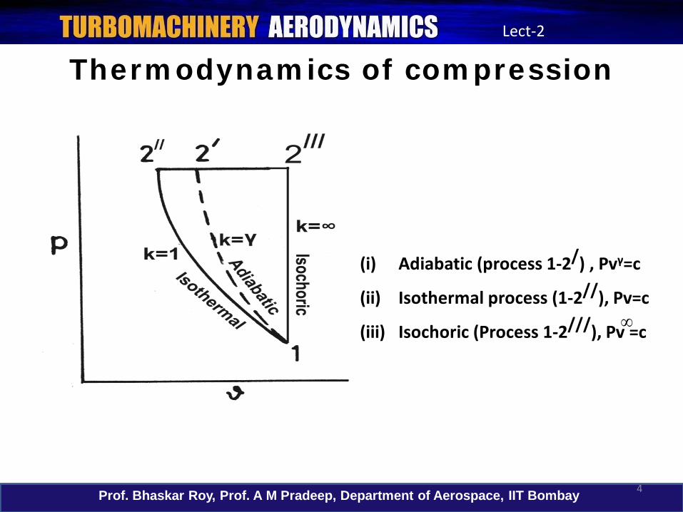
Thermodynamics of compression
(i) Adiabatic (process 1-2/) , Pvγ=c
(ii) Isothermal process (1-2//), Pv=c
(iii) Isochoric (Process 1-2///), Pv =c ∞
Prof. Bhaskar Roy, Prof. A M Pradeep, Department of Aerospace, IIT Bombay 5
Lect-2
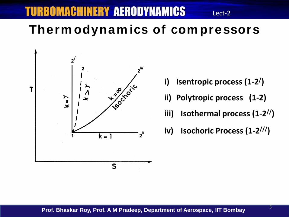
Thermodynamics of compressors
i) Isentropic process (1-2/)
ii) Polytropic process (1-2)
iii) Isothermal process (1-2//)
iv) Isochoric Process (1-2///)

Prof. Bhaskar Roy, Prof. A M Pradeep, Department of Aerospace, IIT Bombay 6
Lect-2
Thermodynamics of compressors
• The compressionprocess is usually expressed in H-s or T-s diagrams.
• The ideal compression process is assumed to be isentropic.
• Deviation from this is expressed as isentropic efficiency.

Prof. Bhaskar Roy, Prof. A M Pradeep, Department of Aerospace, IIT Bombay 7
Lect-2
Thermodynamics of compressors
X1 , X2 are the losses in the rotor and the stator respectively
Compression in terms of static parameters

Prof. Bhaskar Roy, Prof. A M Pradeep, Department of Aerospace, IIT Bombay 8
Lect-2
Thermodynamics of compressors
Compression in terms of total parameters

Prof. Bhaskar Roy, Prof. A M Pradeep, Department of Aerospace, IIT Bombay 9
Lect-2
Thermodynamics of multi-stage compressors
• The flow at the rotor exit with high kinetic energy is still to be converted to static pressure through diffusion.
• The exit kinetic energy of a compressor is of the same order as the entry kinetic energy and the entire work input is expected to be converted to pressure.
Rotor isentropic, stator isothermalRotor polytropic, stator isothermal
Averaged T-s characteristics

Prof. Bhaskar Roy, Prof. A M Pradeep, Department of Aerospace, IIT Bombay 10
Lect-2
Basic operation of axial compressors• Axial flow compressors usually consists of a
series of stages.• Each stage comprises of a row of rotor
blades followed by a row of stator blades.• The working fluid is initially accelerated by
the rotor blades and then decelerated in the stator passages.
• In the stator, the kinetic energy transferred in the rotor is converted to static pressure.
• This process is repeated in several stages to yield the necessary overall pressure ratio.

Prof. Bhaskar Roy, Prof. A M Pradeep, Department of Aerospace, IIT Bombay 11
Lect-2
Basic operation of axial compressors• The compression process consists of a series of
diffusions.• This occurs both in the rotor as well as the
stator. • Due to motion of the rotor blades two distinct
velocity components: absolute and relative velocities in the rotor.
• The absolute velocity of the fluid is increased in the rotor, whereas the relative velocity is decreased, leading to diffusion.
• Per stage pressure ratio is limited because a compressor operates in an adverse pressure gradient environment.
Prof. Bhaskar Roy, Prof. A M Pradeep, Department of Aerospace, IIT Bombay 12
Lect-2
Basic operation of axial compressors
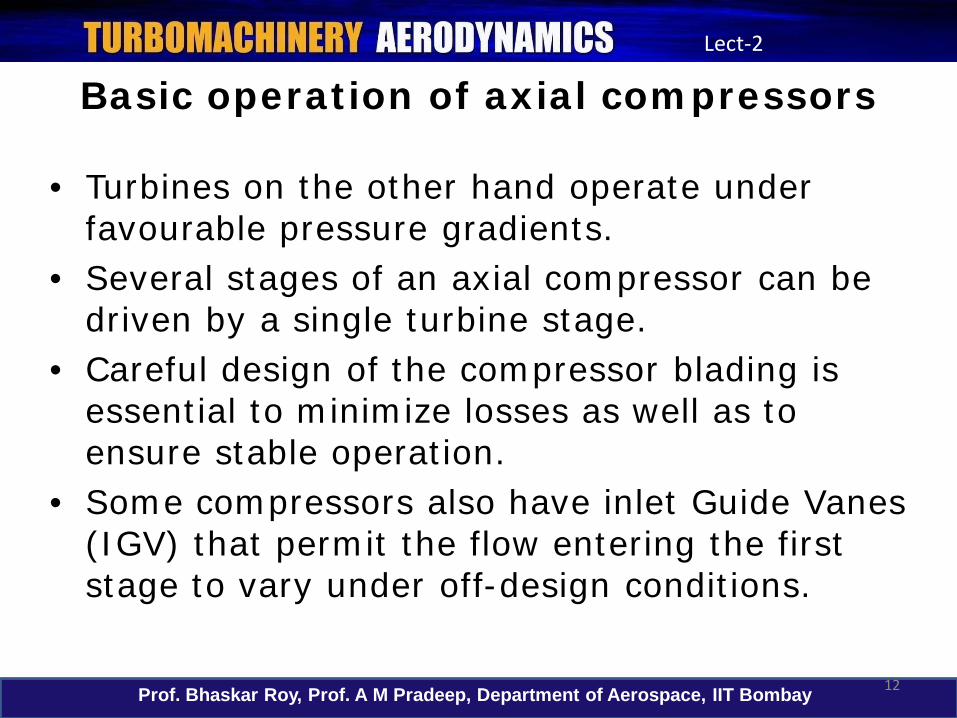
• Turbines on the other hand operate under favourable pressure gradients.
• Several stages of an axial compressor can be driven by a single turbine stage.
• Careful design of the compressor blading is essential to minimize losses as well as to ensure stable operation.
• Some compressors also have inlet Guide Vanes (IGV) that permit the flow entering the first stage to vary under off-design conditions.

Prof. Bhaskar Roy, Prof. A M Pradeep, Department of Aerospace, IIT Bombay 13
Lect-2
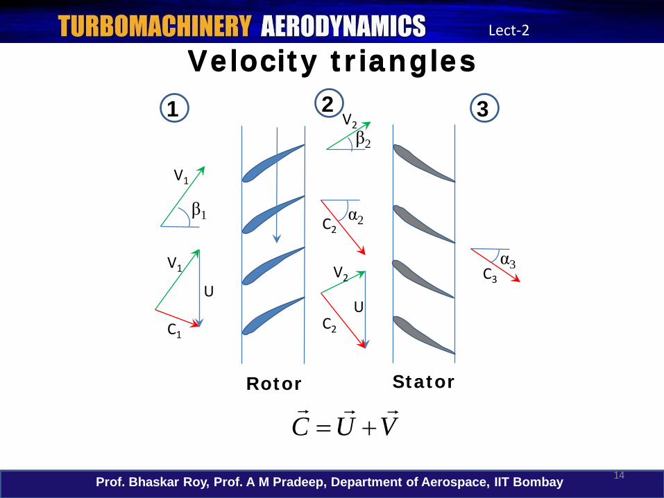
Velocity triangles• Elementary analysis of axial compressors begins
with velocity triangles.• The analysis will be carried out at the mean height
of the blade, where the peripheral velocity or the blade speed is, U.
• The absolute component of velocity will be denoted by, C and the relative component by, V.
• The axial velocity (absolute) will be denoted by Caand the tangential components will be denoted by subscript w (for eg, Cw or Vw)
• α denotes the angle between the absolute velocity with the axial direction and β the corresponding angle for the relative velocity.
Prof. Bhaskar Roy, Prof. A M Pradeep, Department of Aerospace, IIT Bombay 14
Lect-2
Velocity trianglesVelocity triangles
U
C1C2
C3V1 V2
V2
C2
Rotor Stator
1 2 3
β1
β2
α2
α3
U
V1
VUC
+=

Prof. Bhaskar Roy, Prof. A M Pradeep, Department of Aerospace, IIT Bombay 15
Lect-2
Velocity trianglesVelocity triangles
U
C1
C2
Ca
V1
V2
β1
β2α2
α1
ΔCw
Vw2
Vw1
Cw2
Cw1

Prof. Bhaskar Roy, Prof. A M Pradeep, Department of Aerospace, IIT Bombay 16
Lect-2
Property changes across a stage
Total enthalpy
Absolute velocity
Static pressure
C1 C2 C3
h01 h02 h03
P1 P2 P3

Prof. Bhaskar Roy, Prof. A M Pradeep, Department of Aerospace, IIT Bombay 17
Lect-2
Work and compression• Assuming Ca=Ca1=Ca2, from the velocity
triangles, we can see that
• By considering the change in angular momentum of the air passing through the rotor, work done per unit mass flow is
2211 βαβα tantanCUandtantan
CU
aa
+=+=
( )
ly.respective rotor, theafter and before velocity fluid the of components tangential the areC and C where,CCUw wwww 2112 −=

Prof. Bhaskar Roy, Prof. A M Pradeep, Department of Aerospace, IIT Bombay 18
Lect-2
Work and compression
w
a
a
CUw words,other In)tan(tanUCw
)tan(tan)tan(tan,Since)tan(tanUCw
as, written be also can equation above The
Δββ
ββαααα
=
−=∴
−=−
−=
21
2112
12
• The input energy will reveal itself in the form of rise in stagnation temperature of the air.
• The work done as given above will also be equal to the change in stagnation enthalpy across the stage.

Prof. Bhaskar Roy, Prof. A M Pradeep, Department of Aerospace, IIT Bombay 19
Lect-2
Work and compression
01
0
01
03
0103
0103
0203
0101
00102
0102
1TT
TT
as expressed be can Thishhhh
as ,,efficiency stage define us LetTT stator, the through passes fluid the
as done iswork no and adiabatic is flow the SinceTcCU
TT
cCUTT
CUhh
sts
sst
st
p
w
p
w
w
Δη
η
η
ΔΔΔΔ
+=
−−
=
=
=⇒=−
=−

Prof. Bhaskar Roy, Prof. A M Pradeep, Department of Aerospace, IIT Bombay 20
Lect-2
Work and compression
( )
( )1
0101
03
1
01
0
01
03
01030
1
1
−
−
+=
+=
−=
γγ
γγ
Δη
Δη
/
p
wst
/
st
TcCU
PP
give, to equationearlier the with combined be can This
TT
PP
ratio, pressure of terms InTTΔT equation, above the In
Prof. Bhaskar Roy, Prof. A M Pradeep, Department of Aerospace, IIT Bombay 21
Lect-2
Work and compression• From the above equation that relates the
per stage temperature rise to the pressure ratio, it can be seen that to obtain a high temperature ratio for a given overall pressure ratio (for minimizing number of stages),– High blade speed: limited by blades stresses– High axial velocity, high fluid deflection
(β1-β2): Aerodynamic considerations and adverse pressure gradients limit the above.

Prof. Bhaskar Roy, Prof. A M Pradeep, Department of Aerospace, IIT Bombay 22
Lect-2
Work and compression• From the above equation that relates the
per stage temperature rise to the pressure ratio, it can be seen that to obtain a high temperature ratio for a given overall pressure ratio (for minimizing number of stages),– High blade speed: limited by blades stresses– High axial velocity, high fluid deflection
(β1-β2): Aerodynamic considerations and adverse pressure gradients limit the above.

Prof. Bhaskar Roy, Prof. A M Pradeep, Department of Aerospace, IIT Bombay 23
Lect-2
In this lecture...
• Axial flow compressors and fans– Thermodynamics of compression
– P-v and T-s diagrams of compressors– Thermodynamics of compression
process– Multi-stage compression
– Basic operation of axial compressors/fans– Velocity triangles– Work and compression

Prof. Bhaskar Roy, Prof. A M Pradeep, Department of Aerospace, IIT Bombay 24
Lect-2
In the next lecture...
• Two-dimensional analytical model• Performance parameters• Cascade aerodynamics


