W0-1 AGH 2014 April, 2014 Lecture-0 ANSYS in how to start From zero to results W0:Introduction W0-2 ANSYS Warsztaty . April, 2014 AGH AGH –WEiP Schedule Workshop plan Week 1 - Quick start in ANSYS Week 2 – Geometry –DesignModeler (DM) Week 3 – Mesh – Meshing Week 4 – Solver – FLUENT/CFX Week 5 - Post Processing Week 6 – Import/Export, Data Visualisation Week 7 – Exam
Transcript
W0-1AGH 2014 April, 2014
Lecture-0
ANSYS in how to start
From zero to results
W0:Introduction
W0-2ANSYS Warsztaty.
April, 2014AGH
AGH –WEiPSchedule
Workshop plan
Week 1 - Quick start in ANSYS
Week 2 – Geometry –DesignModeler (DM)
Week 3 – Mesh – Meshing
Week 4 – Solver – FLUENT/CFX
Week 5 - Post Processing
Week 6 – Import/Export, Data Visualisation
Week 7 – Exam
W0:Introduction
W0-3ANSYS Warsztaty.
April, 2014AGH
AGH –WEiPANSYS
Exercise plan
• Week 1 – Steady problems
• Week 2 – Unsteady problems
• Week 3 – Convection
• Week 4 – Turbulent Flows
• Week 5 – Turbomaschinery
• Week 6 – Complex tasks, multiphase flows
• Week 7 – Exam
W0:Introduction
W0-4ANSYS Warsztaty.
April, 2014AGH
AGH –WEiPGoals
• Goals:
–ANSYS in 45 minutes
–Workbench Overview
–Navigate through the GUI viewing controls.
–ANSYS DesignModeler (DM) Overview
–Draw and dimension a 2-D sketch on the new plane (dimensioning will adequately specify the size and location of the sketch)
–ANSYS Meshing (AM) Overview
–Solution- Tutorial #1: 2D plate
–Post-processing
W0:Introduction
W0-5ANSYS Warsztaty.
April, 2014AGH
AGH –WEiPRuning ANSYS
• Uruchamianie systemu ANSYS
Program ANSYS, jako dość wszechstronne i złożone narzędzie, możepracować w różnych trybach, począwszy od trybu wsadowego,poprzez różne interfejsy graficzne, a skończywszy na najbardziejrozbudowanym interfejsie graficznym ANSYS Workbench,umożliwiającym modelowanie złożonych struktur przestrzennych wśrodowisku przypominającym systemy CAD. Poniżej omówiony zostaniestandardowy tryb pracy interaktywnej dostępny w każdej instalacji ikonfiguracji ANSYSa. Warto w tym miejscu nadmienić, że wzaawansowanych zastosowaniach dość przydatny jest również na pozórprzestarzały już tryb wsadowy
We are going tu work in most advanced ANSYS Workbench
W0:Introduction
W0-6ANSYS Warsztaty.
April, 2014AGH
AGH –WEiPANSYS Workbench
• What is Workbench?
– Platform for integration of all ANSYS analysis tools.
– Solid mechanics, fluid dynamics, EM, optimization, etc.
– Entire project contained in common platform:
– geometry creation, meshing, analysis, and
– post-processing.
W0:Introduction
W0-7ANSYS Warsztaty.
April, 2014AGH
AGH –WEiP
• To start Workbench - Double click on ANSYS Workbench 15 icon
Starting Workbench
W0:Introduction
W0-8ANSYS Warsztaty.
April, 2014AGH
AGH –WEiPWorkbench Overview
W0:Introduction
W0-9ANSYS Warsztaty.
April, 2014AGH
AGH –WEiPThe Workbench Graphical User Interface
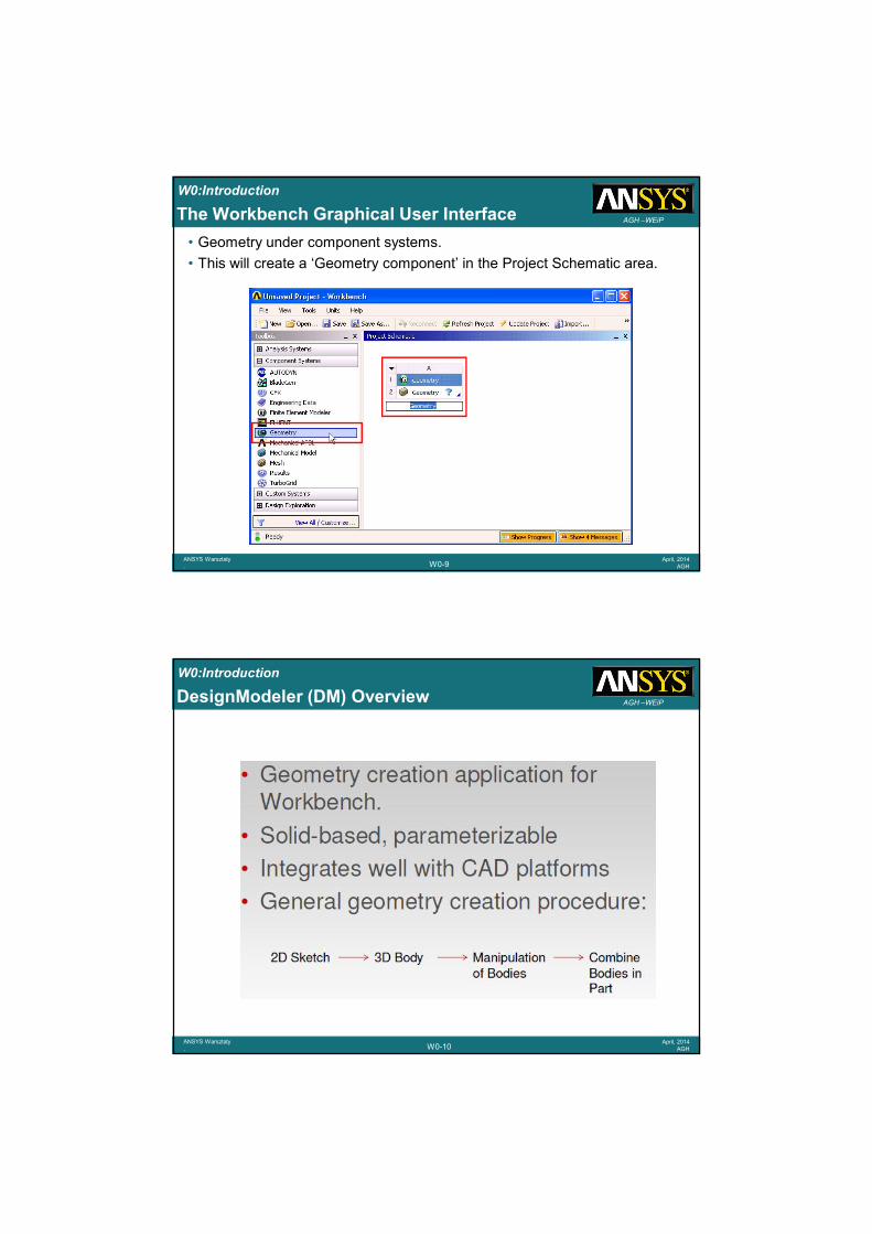
• Geometry under component systems.
• This will create a ‘Geometry component’ in the Project Schematic area.
W0:Introduction
W0-10ANSYS Warsztaty.
April, 2014AGH
AGH –WEiPDesignModeler (DM) Overview
W0:Introduction
W0-11ANSYS Warsztaty.
April, 2014AGH
AGH –WEiP
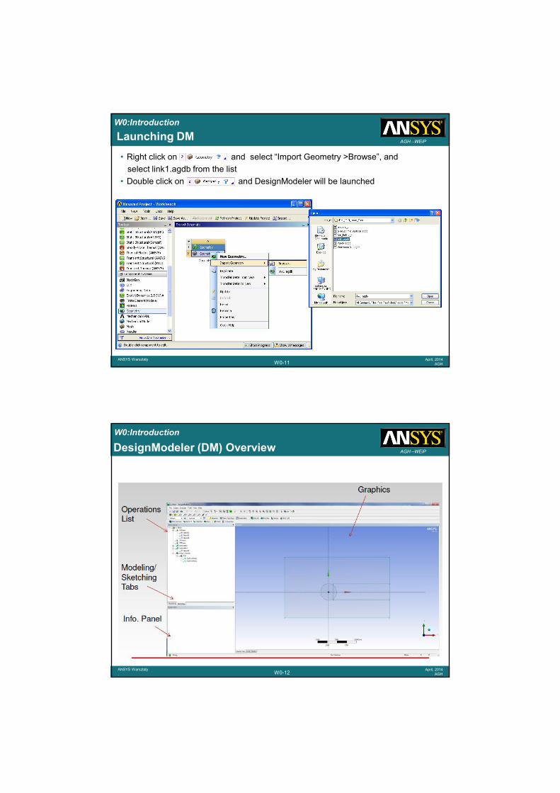
• Right click on and select “Import Geometry >Browse”, and
select link1.agdb from the list
• Double click on and DesignModeler will be launched
Launching DM
W0:Introduction
W0-12ANSYS Warsztaty.
April, 2014AGH
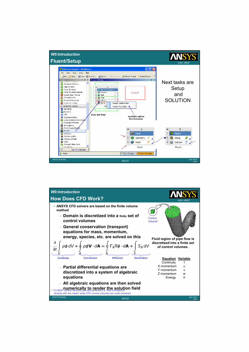
AGH –WEiPDesignModeler (DM) Overview
W0:Introduction
W0-13ANSYS Warsztaty.
April, 2014AGH
AGH –WEiPMesh
Next task to geometry is
mesh
W0:Introduction
W0-14ANSYS Warsztaty.
April, 2014AGH
AGH –WEiPWhat is the “ANSYS Meshing Application”?
• ANSYS has been working to integrate “best in class” technologies from several sources:– ICEM CFD
– TGrid
– GAMBIT
– CFX
– ANSYS Prep/Post
– Etc.
W0:Introduction
W0-15ANSYS Warsztaty.
April, 2014AGH
AGH –WEiPANSYS Meshing Application Overview
• The objective of the ANSYS Meshing Application in Workbench is to provide access to common ANSYS Inc. meshing tools in a single location, for use by any analysis type:
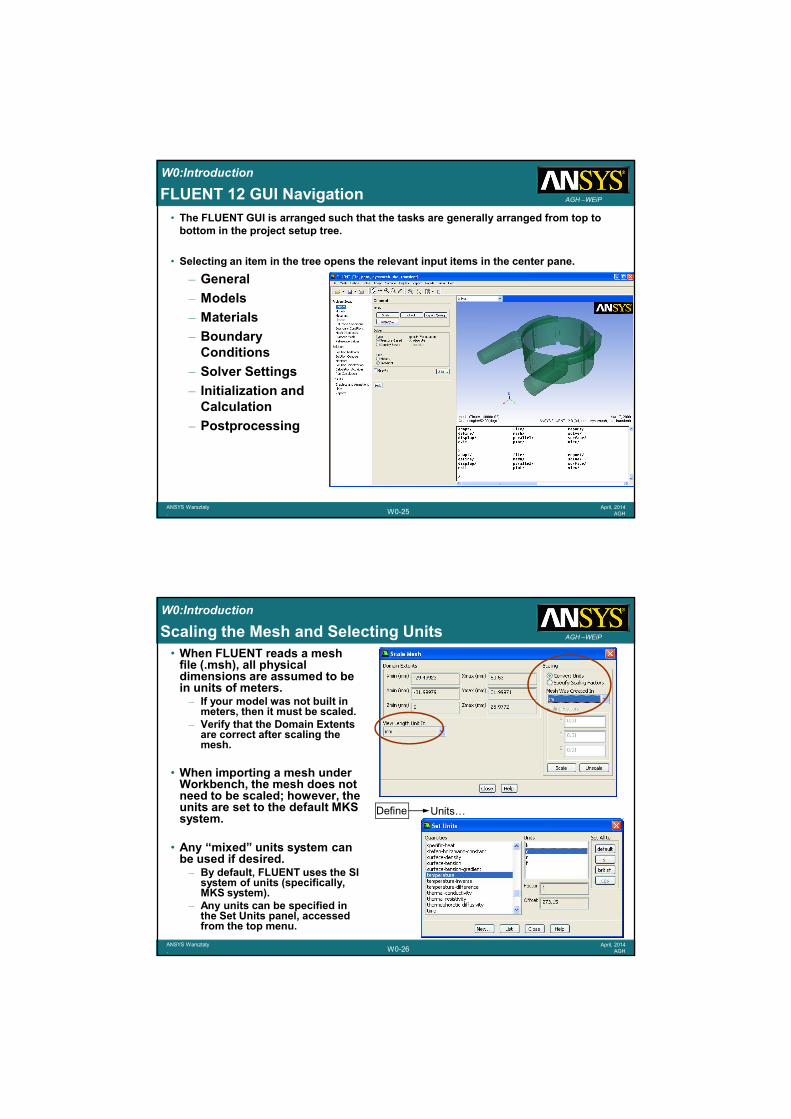
AGH –WEiPSOLVER• Parallel processing can be used to run
FLUENT on multiple processors to decrease turnaround time and increase simulation efficiency.– Critical for cases involving large meshes
and/or complex physics.– FLUENT is fully parallelized and capable of
running across most hardware and software configurations, such as compute clusters or multi-processor machines.
• Parallel FLUENT can be launched either using the system command prompt or using the FLUENT Launcher panel.– For example, to launch an n-CPU parallel
session, use the commandfluent 3d –tn
• The mesh can be partitioned either manually or automatically using a number of different methods.– Non-conformal meshes, sliding mesh
interfaces and shell conduction zones require partitioning in serial.
• A web-based lecture is available on the FLUENT User Services Center.
W0:Introduction
W0-25ANSYS Warsztaty.
April, 2014AGH
AGH –WEiPFLUENT 12 GUI Navigation
• The FLUENT GUI is arranged such that the tasks are generally arranged from top to bottom in the project setup tree.
• Selecting an item in the tree opens the relevant input items in the center pane.
– General
– Models
– Materials
– BoundaryConditions
– Solver Settings
– Initialization andCalculation
– Postprocessing
W0:Introduction
W0-26ANSYS Warsztaty.
April, 2014AGH
AGH –WEiPScaling the Mesh and Selecting Units
• When FLUENT reads a mesh file (.msh), all physical dimensions are assumed to be in units of meters.– If your model was not built in
meters, then it must be scaled.– Verify that the Domain Extents
are correct after scaling the mesh.
• When importing a mesh under Workbench, the mesh does not need to be scaled; however, the units are set to the default MKS system.
• Any “mixed” units system can be used if desired.– By default, FLUENT uses the SI
system of units (specifically, MKS system).
– Any units can be specified in the Set Units panel, accessed from the top menu.
Define Units…
W0:Introduction
W0-27ANSYS Warsztaty.
April, 2014AGH
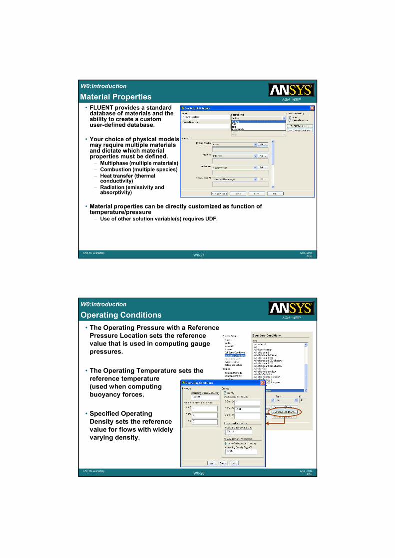
AGH –WEiPMaterial Properties
• FLUENT provides a standarddatabase of materials and theability to create a customuser-defined database.
• Your choice of physical modelsmay require multiple materialsand dictate which materialproperties must be defined.– Multiphase (multiple materials)– Combustion (multiple species)– Heat transfer (thermal
conductivity)– Radiation (emissivity and
absorptivity)
• Material properties can be directly customized as function of temperature/pressure– Use of other solution variable(s) requires UDF.
W0:Introduction
W0-28ANSYS Warsztaty.
April, 2014AGH
AGH –WEiPOperating Conditions
• The Operating Pressure with a Reference Pressure Location sets the reference value that is used in computing gauge pressures.
• The Operating Temperature sets the reference temperature(used when computing buoyancy forces.
• Specified Operating Density sets the reference value for flows with widely varying density.
W0:Introduction
W0-29ANSYS Warsztaty.
April, 2014AGH
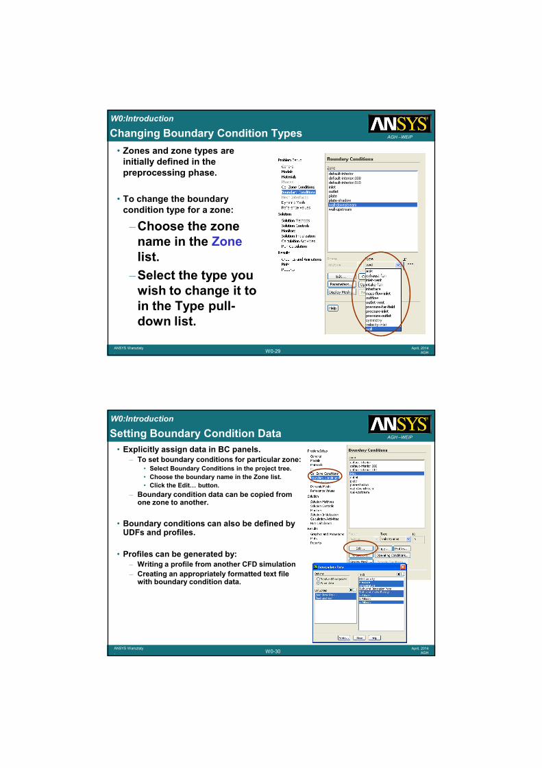
AGH –WEiPChanging Boundary Condition Types
• Zones and zone types are initially defined in the preprocessing phase.
• To change the boundary condition type for a zone:
–Choose the zone name in the Zonelist.
–Select the type you wish to change it to in the Type pull-down list.
W0:Introduction
W0-30ANSYS Warsztaty.
April, 2014AGH
AGH –WEiPSetting Boundary Condition Data
• Explicitly assign data in BC panels.– To set boundary conditions for particular zone:
• Select Boundary Conditions in the project tree.
• Choose the boundary name in the Zone list.
• Click the Edit… button.
– Boundary condition data can be copied from one zone to another.
• Boundary conditions can also be defined by UDFs and profiles.
• Profiles can be generated by:– Writing a profile from another CFD simulation
– Creating an appropriately formatted text file with boundary condition data.
W0:Introduction
W0-31ANSYS Warsztaty.
April, 2014AGH
AGH –WEiPVelocity Inlet
• Velocity Specification Method
–Magnitude, Normal to Boundary
–Components
–Magnitude and Direction
• Applies a uniform velocity profileat the boundary, unless UDF orprofile is used.
• Velocity inlets are intended foruse in incompressible flows andare not recommended for compressible flows.
• Velocity Magnitude input can be negative, implying that you can prescribe the exit velocity.
W0:Introduction
W0-32ANSYS Warsztaty.
April, 2014AGH
AGH –WEiPWall Boundary Conditions
• Five thermal conditions
– Heat Flux
– Temperature
– Convection – simulates an external convection environment which is not modeled (user-prescribed heat transfer coefficient).
– Radiation – simulates an external radiation environment which is not modeled (user-prescribed external emissivity and radiation temperature).
– Mixed – Combination of Convection and Radiation boundary conditions.
• Wall material and thickness can be defined for 1D or shell conduction calculations. heat transfer calculations.
W0:Introduction
W0-33ANSYS Warsztaty.
April, 2014AGH
AGH –WEiPProblem Setup – Heat Source
• An energy (heat) source is added to the solid zone to simulate the heat generation by the heat-generating electronic components.
W0:Introduction
W0-34ANSYS Warsztaty.
April, 2014AGH
AGH –WEiPTemperature Distribution (Front and Top View)
Flowdirection
Convection Boundary1.5 W/m2 K298 K free stream temp.
Convection boundary1.5 W/m2 K298 K free stream tempFront View
Top View(image mirrored about symmetry plane)
Elect. Component(solid zone)2 Watts source
Board(solid zone)
Air (fluid zone)
298
426
410
394
378
362
346
330
314
Temp.(ºF)
Flowdirection
W0:Introduction
W0-35ANSYS Warsztaty.
April, 2014AGH
AGH –WEiPConvergence Monitors – Residuals
• Residual plots show when the residual values have reached the specified tolerance.
All equationsconverged.
10-3
10-6
W0:Introduction
W0-36ANSYS Warsztaty.
April, 2014AGH
AGH –WEiPResults
NOW We are going
to the last stepRESULTS
W0:Introduction
W0-37ANSYS Warsztaty.
April, 2014AGH
AGH –WEiPStarting CFD-Post
• Within ANSYS Workbench– Drag the CFD-Post icon in the
Component Systems list tothe project tree.
– OR, create a standaloneCFD-Post session.
• From the Start Menu or Command Line– Start > Programs > ANSYS 12.0 > ANSYS CFD-Post
• CFD-Post can also be started from the CFX-Solver Manager or the CFX Launcher
W0:Introduction
W0-38ANSYS Warsztaty.
April, 2014AGH
AGH –WEiPGUI Layout
Outline tab (“model tree”)
Details view
Additional tabs (various tools)
Various Viewers (3D, Chart, …)
W0:Introduction
W0-39ANSYS Warsztaty.
April, 2014AGH
AGH –WEiP
1. Prepare locations where data will be extracted from or plots generated
2. Create variables/expressions which will be used to extract data (if necessary)
3. i) Generate qualitative dataat locations
ii) Generate quantitative
data at locations
4. Generate Reports
CFD-Post General Workflow
W0:Introduction
W0-40ANSYS Warsztaty.
April, 2014AGH
AGH –WEiPCreating Locations
• Locations are created from the Insert menu or from the toolbar
• Once created, all Locations appear as entries in the Outline tree
Use the check boxes next to each object in the Outline tree to quickly control visibility
Double-click objects in the Outline tree to edit
Right-click objects in the Outline tree to Duplicate or Delete
W0:Introduction
W0-41ANSYS Warsztaty.
April, 2014AGH
AGH –WEiP
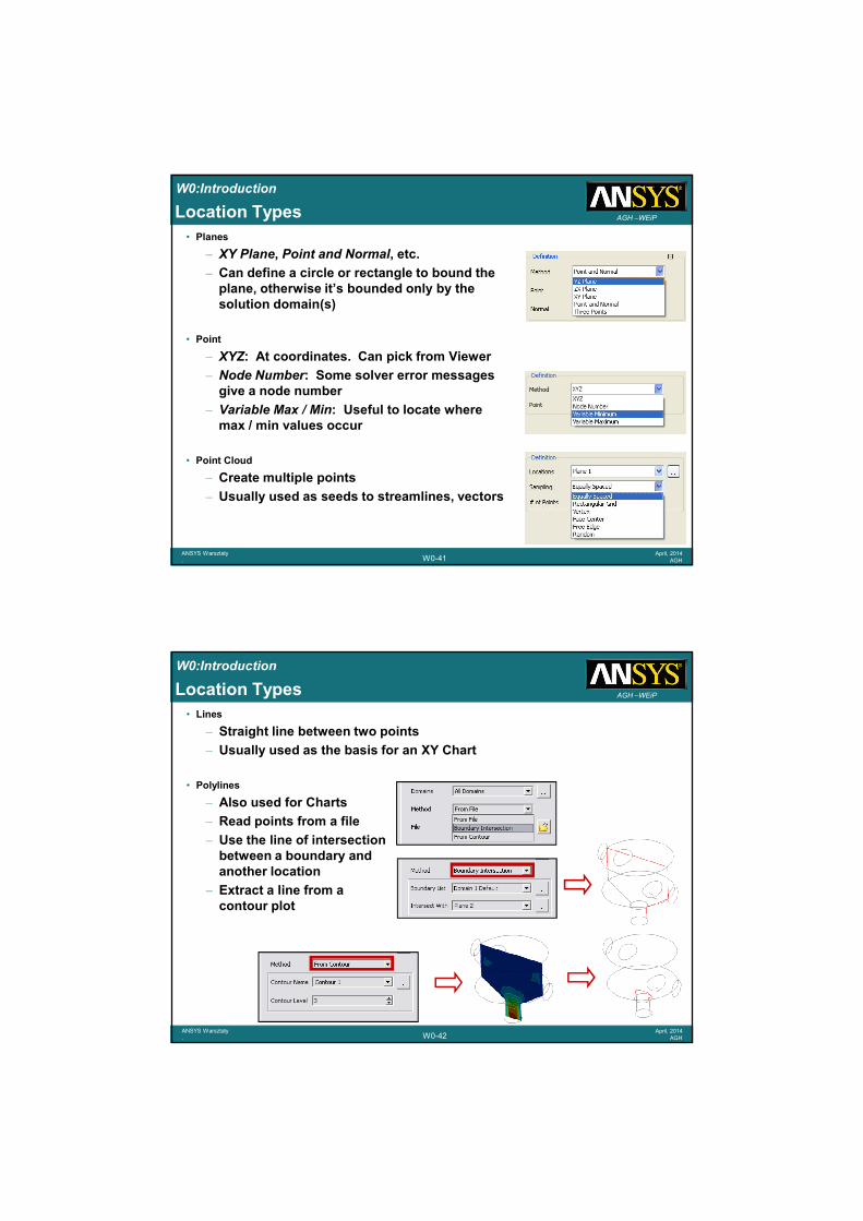
• Planes
– XY Plane, Point and Normal, etc.
– Can define a circle or rectangle to bound the plane, otherwise it’s bounded only by the solution domain(s)
• Point
– XYZ: At coordinates. Can pick from Viewer
– Node Number: Some solver error messages give a node number
– Variable Max / Min: Useful to locate where max / min values occur
• Point Cloud
– Create multiple points
– Usually used as seeds to streamlines, vectors
Location Types
W0:Introduction
W0-42ANSYS Warsztaty.
April, 2014AGH
AGH –WEiPLocation Types
• Lines
– Straight line between two points
– Usually used as the basis for an XY Chart
• Polylines
– Also used for Charts
– Read points from a file
– Use the line of intersectionbetween a boundary andanother location
– Extract a line from acontour plot
W0:Introduction
W0-43ANSYS Warsztaty.
April, 2014AGH
AGH –WEiPLocation Types
• Volumes
– Elements are either in or out
• No cut volumes
– From Surface• A volume is formed from all elements
touching (or above / below) the selected location
• Can be useful for mesh checking
– Isovolume• Base on a variable at, above or below a
given value, or between two values
W0:Introduction
W0-44ANSYS Warsztaty.
April, 2014AGH
AGH –WEiPLocation Types
• Isosurfaces
– Surface of a variable at a specified value
• Iso Clip
– An Iso Clip takes a copy of any existing location and then clips it using one or more criteria
• E.g. a outlet boundary plot which is then clipped by Velocity >= 10 [m/s] and Velocity <= 20 [m/s]
– Can clip using any variable, including geometric variables
Isosurface of pressure behind a flap valve
W0:Introduction
W0-45ANSYS Warsztaty.
April, 2014AGH
AGH –WEiP
• Timestep Selector
– Transient results are post-processed by loading in the end results file, then selecting different timesteps from the Timestep Selector
• Animation
– Animate objects, create MPEGs
– More on next slide
• Quick Editor
– Provides a very quick way to change the “primary” value associated with each object
• Probe
– Pick a point from the Viewer and probe a variable value at that point
Other Tools
Timestep Animation Quick ProbeSelector Editor
W0:Introduction
W0-46ANSYS Warsztaty.
April, 2014AGH
AGH –WEiPCase Comparison
• When multiple files are loaded you can select Case Comparison from the Outline tree
– Automatically generates difference variables and plots
k-eSST
Difference Plot
• Expression syntax:– function()@CASE:#.Location
– E.g: areaAve(Pressure)@CASE:1.Inlet
W0:Introduction
W0-47ANSYS Warsztaty.
April, 2014AGH
AGH –WEiPFiles
• Results– ANSYS – CFD Post can read ANSYS
results for temperature, velocity, acceleration, magnetic forces, stress, strain, and mesh deformation
• Import– Locations – .csv files which contain
point data which defines a polyline or surface
– ANSYS Surface Mesh (.cdb): To allow for export of data on a surface for use as a boundary condition in ANSYS
• Export– Profile Boundary Data: for use in CFX-Pre
– General formatted results data
– ANSYS Load Data: Written onto an imported ANSYS .cdb file