216
1 Lecture 1
| Date post: | 30-Dec-2015 |
| Category: |
Documents |
| Upload: | marvene-grealish |
| View: | 44 times |
| Download: | 0 times |

1
Lecture 1

2
Software Engineering

3
Organization of this Lecture:
What is Software Engineering? Programs vs. Software Products Evolution of Software Engineering Notable Changes In Software
Development Practices Introduction to Life Cycle Models Summary

4
What is Software Engineering?
Engineering approach to develop software.Building Construction Analogy.
Systematic collection of past experience:techniques, methodologies,guidelines.

5
Why Study Software Engineering? (1)
To acquire skills to develop large programs. Exponential growth in complexity and
difficulty level with size.The ad hoc approach breaks down when
size of software increases: --- “One thorn of experience is worth a whole wilderness of warning.”

6
Why Study Software Engineering? (2)
Ability to solve complex programming problems: How to break large projects into
smaller and manageable parts?Learn techniques of:
specification, design, interface development, testing, project management, etc.
7
Why Study Software Engineering? (3)
To acquire skills to be a better programmer:
Higher Productivity Better Quality Programs

8
Software Crisis
Software products:fail to meet user requirements.frequently crash.expensive.difficult to alter, debug, and
enhance.often delivered late.use resources non-optimally.

9
Software Crisis (cont.)
Year
Hw costSw cost
Relative Cost of Hardware and Software1960 1999

10
Factors contributing to the software crisis
Larger problems, Lack of adequate training in
software engineering, Increasing skill shortage, Low productivity
improvements.

11
Programs versus Software Products
Usually small in size Author himself is sole
user Single developer Lacks proper user
interface Lacks proper
documentation Ad hoc development.
Large Large number of
users Team of developers Well-designed
interface Well documented &
user-manual prepared
Systematic development
12
Computer Systems Engineering
Computer systems engineering: encompasses software
engineering.Many products require
development of software as well as specific hardware to run it: a coffee vending machine, a mobile communication product, etc.
13
Computer Systems Engineering
The high-level problem:deciding which tasks are to be
solved by software which ones by hardware.

14
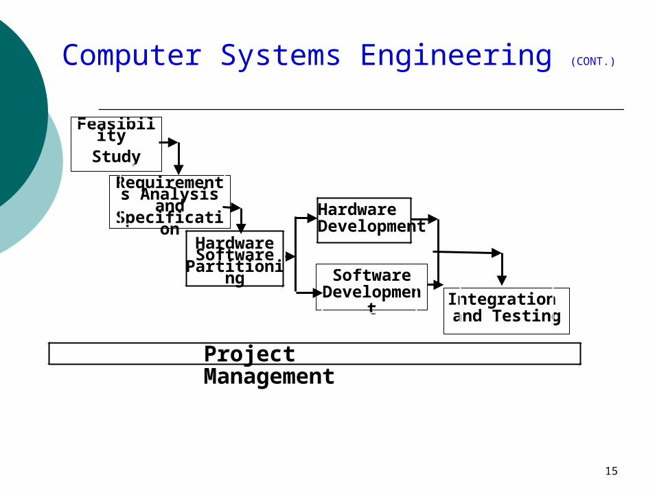
Computer Systems Engineering (CONT.)
Often, hardware and software are developed together:Hardware simulator is used during
software development. Integration of hardware and
software. Final system testing
15
Computer Systems Engineering (CONT.)
Feasibility Study
Requirements Analysis and Specification
Hardware Software
Partitioning
Hardware Development
Software Development Integration
and Testing
Project Management

16
Emergence of Software Engineering
Early Computer Programming (1950s):Programs were being written in
assembly language. Programs were limited to about
a few hundreds of lines of assembly code.

17
Early Computer Programming (50s)
Every programmer developed his own style of writing programs:according to his intuition
(exploratory programming).

18
High-level languages such as FORTRAN, ALGOL, and COBOL were introduced:This reduced software
development efforts greatly.
High-Level Language Programming (Early 60s)

19
Control Flow-Based Design (late 60s)
Size and complexity of programs increased further:exploratory programming style
proved to be insufficient. Programmers found:
very difficult to write cost-effective and correct programs.

20
Control Flow-Based Design (late 60s)
A program's control structure indicates: the sequence in which the program's
instructions are executed. To help design programs having
good control structure:flow charting technique was
developed.

21
Control Flow-Based Design (late 60s)
Using flow charting technique: one can represent and design a program's control structure.
Usually one understands a program:by mentally simulating the program's execution sequence.

111 22
Control Flow-Based Design (Late 60s)
A program having a messy flow chart representation: difficult to understand and debug.

23
Structured Programming
A program is called structured when it uses only the
following types of constructs:sequence, selection, iteration

24
Structured programs
Unstructured control flows are avoided.
Consist of a neat set of modules.
Use single-entry, single-exit program constructs.

25
However, violations to this feature are permitted:due to practical considerations such as:premature loop exit to support exception handling.
Structured programs

26
Structured programs
Structured programs are:Easier to read and understand,
easier to maintain, require less effort and time for development.

27
Structured Programming
Research experience shows: programmers commit less number of errors while using structured if-then-else and do-while statements
compared to test-and-branch constructs.

28
Data Structure-Oriented Design (Early 70s)
Soon it was discovered:it is important to pay more attention to the design of data structures of a program than to the design of its control structure.

29
Data Structure-Oriented Design (Early 70s)
Techniques which emphasize designing the data structure: derive program structure from
it:called data structure-data structure-oriented design oriented design techniques.techniques.

30
Data Flow-Oriented Design (Late 70s)
Data flow-oriented techniques advocate: the data items input to a system
must first be identified, processing required on the data
items to produce the required outputs should be determined.

31
Data Flow-Oriented Design (Late 70s)
Data flow technique identifies:different processing stations (functions) in a system
the items (data) that flow between processing stations.

32
Data Flow-Oriented Design (Late 70s)
Data flow technique is a generic technique:can be used to model the working of
any systemnot just software systems.
A major advantage of the data flow technique is its simplicity.

33
Data Flow Model of a Car Assembly Unit
FitEngine
Paint and Test
FitWheels
FitDoors
Chassis Store
Door Store
Wheel Store
Engine Store
Car
Partly Assembled Car
Assembled Car
Chassis with Engine

34
Object-Oriented Design (80s)
Object-oriented technique:an intuitively appealing design
approach: natural objects (such as
employees, pay-roll-register, etc.) occurring in a problem are first identified.

35
Object-Oriented Design (80s)
Relationships among objects:such as composition, reference,
and inheritance are determined. Each object essentially acts as
a data hiding (or data abstraction) entity.

36
Object-Oriented Design (80s)
Object-Oriented Techniques have gained wide acceptance:SimplicityReuse possibilitiesLower development time and
costMore robust codeEasy maintenance

37
Evolution of Design Techniques
Object-Oriented
Ad hoc
Data flow-based
Data structure-based
Control flow-based
38
Evolution of Other Software Engineering Techniques
The improvements to the software design methodologiesare indeed very conspicuous.
In additions to the software design techniques: several other techniques
evolved.
39
Evolution of Other Software Engineering Techniques
life cycle models, specification techniques, project management techniques, testing techniques, debugging techniques, quality assurance techniques, software measurement
techniques, CASE tools, etc.
40
Differences between the exploratory style and modern software development practices
Use of Life Cycle Models Software is developed through
several well-defined stages: requirements analysis and
specification,design, coding, testing, etc.

41
Differences between the exploratory style and modern software development practices
Emphasis has shifted from error correction to error
prevention. Modern practices emphasize:
detection of errors as close to their point of introduction as possible.

42
Differences between the exploratory style and modern software development practices (CONT.)
In exploratory style, errors are detected only during testing,
Now, focus is on detecting as many errors as possible in each phase of development.
43
Differences between the exploratory style and modern software development practices (CONT.)
In exploratory style, coding is synonymous with program development.
Now, coding is considered only a small part of program development effort.

44
Differences between the exploratory style and modern software development practices (CONT.)
A lot of effort and attention is now being paid to: requirements specification.
Also, now there is a distinct design phase:standard design techniques are
being used.

45
Differences between the exploratory style and modern software development practices (CONT.)
During all stages of development process:Periodic reviews are being carried
out Software testing has become
systematic:standard testing techniques are
available.
46
Differences between the exploratory style and modern software development practices (CONT.)
There is better visibility of design and code: visibility means production of good quality,
consistent and standard documents. In the past, very little attention was being
given to producing good quality and consistent documents.
We will see later that increased visibility makes software project management easier.

47
Differences between the exploratory style and modern software development practices (CONT.)
Because of good documentation:fault diagnosis and maintenance are
smoother now. Several metrics are being used:
help in software project management, quality assurance, etc.

48
Differences between the exploratory style and modern software development practices (CONT.)
Projects are being thoroughly planned: estimation, scheduling, monitoring mechanisms.
Use of CASE tools.

49
Software Life Cycle
Software life cycle (or software process): series of identifiable stages that a software product undergoes during its life time:
Feasibility studyrequirements analysis and specification, design, coding, testingmaintenance.

50
Life Cycle Model
A software life cycle model (or process model):a descriptive and diagrammatic
model of software life cycle: identifies all the activities required for
product development, establishes a precedence ordering among
the different activities, Divides life cycle into phases.

51
Life Cycle Model (CONT.)
Several different activities may be carried out in each life cycle phase. For example, the design stage might
consist of:structured analysis activity followed by
structured design activity.

52
Why Model Life Cycle ?
A written description:forms a common understanding of
activities among the software developers.
helps in identifying inconsistencies, redundancies, and omissions in the development process.
Helps in tailoring a process model for specific projects.

53
Why Model Life Cycle ?
Processes are tailored for special projects.A documented process model
helps to identify where the tailoring is to occur.

54
Life Cycle Model (CONT.)
The development team must identify a suitable life cycle model:and then adhere to it.Primary advantage of adhering to a
life cycle model:helps development of software in a
systematic and disciplined manner.

55
Life Cycle Model (CONT.)
When a program is developed by a single programmer --- he has the freedom to decide his
exact steps.

56
Life Cycle Model (CONT.)
When a software product is being developed by a team: there must be a precise
understanding among team members as to when to do what,
otherwise it would lead to chaos and project failure.

57
Life Cycle Model (CONT.)
A software project will never succeed if: one engineer starts writing code,another concentrates on writing the
test document first, yet another engineer first defines the
file structureanother defines the I/O for his portion
first.

58
Life Cycle Model (CONT.)
A life cycle model:defines entry and exit criteria
for every phase. A phase is considered to be
complete:only when all its exit criteria are satisfied.

59
Life Cycle Model (CONT.)
The phase exit criteria for the software requirements specification phase: Software Requirements Specification (SRS)
document is complete, reviewed, and approved by the customer.
A phase can start: only if its phase-entry criteria have been
satisfied.

60
Life Cycle Model (CONT.)
It becomes easier for software project managers:to monitor the progress of the
project.
61
Life Cycle Model (CONT.)
Many life cycle models have been proposed.
We will confine our attention to a few important and commonly used models. classical waterfall model iterative waterfall, evolutionary, prototyping, and spiral model

62
Summary
Software engineering is:systematic collection of decades
of programming experience together with the innovations
made by researchers.

63
Summary
A fundamental necessity while developing any large software product: adoption of a life cycle model.

64
Summary
Adherence to a software life cycle model:helps to do various development
activities in a systematic and disciplined manner.
also makes it easier to manage a software development effort.
65
Lecture 2

66
Life Cycle Models

67
Classical Waterfall Model
Classical waterfall model divides life cycle into phases: feasibility study, requirements analysis and
specification, design, coding and unit testing, integration and system testing, maintenance.

68
Classical Waterfall Model
Feasibility Study
Req. Analysis
Design
Coding
Testing
Maintenance

69
Feasibility Study
Main aim of feasibility study:determine whether developing the product financially worthwhile technically feasible.
First roughly understand what the customer wants: different data which would be input to the system, processing needed on these data, output data to be produced by the system, various constraints on the behavior of the system.

70
Activities during Feasibility Study
Work out an overall understanding of the problem.
Formulate different solution strategies.
Examine alternate solution strategies in terms of:
resources required, cost of development, and development time.

71
Activities during Feasibility Study
Perform a cost/benefit analysis: to determine which solution is the
best. you may determine that none of
the solutions is feasible due to: high cost, resource constraints, technical reasons.

72
Requirements Analysis and Specification
Aim of this phase:understand the exact
requirements of the customer, document them properly.
Consists of two distinct activities: requirements gathering and
analysis requirements specification.
73
Goals of Requirements Analysis
Collect all related data from the customer:analyze the collected data to
clearly understand what the customer wants,
find out any inconsistencies and incompleteness in the requirements,
resolve all inconsistencies and incompleteness.

74
Requirements Gathering
Gathering relevant data:usually collected from the end-
users through interviews and discussions.
For example, for a business accounting software:
interview all the accountants of the organization to find out their requirements.

75
Requirements Analysis (CONT.)
The data you initially collect from the users:would usually contain several contradictions and ambiguities:
each user typically has only a partial and incomplete view of the system.

76
Requirements Analysis (CONT.)
Ambiguities and contradictions: must be identified resolved by discussions with the
customers. Next, requirements are organized:
into a Software Requirements Specification (SRS) document.

77
Requirements Analysis (CONT.)
Engineers doing requirements analysis and specification: are designated as
analysts.

78
Design
Design phase transforms requirements specification: into a form suitable for implementation in some programming language.

79
Design In technical terms:
during design phase, software architecture is derived from the SRS document.
Two design approaches: traditional approach, object oriented approach.

80
Traditional Design Approach
Consists of two activities:Structured analysis Structured design

81
Structured Analysis Activity
Identify all the functions to be performed.
Identify data flow among the functions.
Decompose each function recursively into sub-functions. Identify data flow among the
subfunctions as well.

82
Structured Analysis (CONT.)
Carried out using Data flow diagrams (DFDs).
After structured analysis, carry out structured design:architectural design (or high-
level design)detailed design (or low-level
design).

83
Structured Design
High-level design: decompose the system into modules, represent invocation relationships
among the modules.
Detailed design: different modules designed in greater
detail: data structures and algorithms for each
module are designed.

84
Object Oriented Design
First identify various objects (real world entities) occurring in the problem: identify the relationships among the
objects. For example, the objects in a pay-roll
software may be: employees, managers, pay-roll register, Departments, etc.

85
Object Oriented Design (CONT.)
Object structurefurther refined to obtain the
detailed design. OOD has several advantages:
lower development effort, lower development time, better maintainability.
86
Implementation
Purpose of implementation phase (aka coding and unit testing phase):translate software design into source code.
87
Implementation
During the implementation phase: each module of the design is
coded, each module is unit tested
tested independently as a stand alone unit, and debugged,
each module is documented.

88
Implementation (CONT.)
The purpose of unit testing:test if individual modules work
correctly. The end product of
implementation phase: a set of program modules that
have been tested individually.

89
Integration and System Testing
Different modules are integrated in a planned manner: modules are almost never integrated
in one shot. Normally integration is carried out
through a number of steps.
During each integration step, the partially integrated system is
tested.

90
Integration and System Testing
M1
M4M3
M2
91
System Testing
After all the modules have been successfully integrated and tested: system testing is carried out.
Goal of system testing: ensure that the developed system functions according to its requirements as specified in the SRS document.

92
Maintenance
Maintenance of any software product: requires much more effort than
the effort to develop the product itself.
development effort to maintenance effort is typically 40:60.

93
Maintenance (CONT.)
Corrective maintenance: Correct errors which were not discovered
during the product development phases. Perfective maintenance:
Improve implementation of the system enhance functionalities of the system.
Adaptive maintenance: Port software to a new environment,
e.g. to a new computer or to a new operating system.

94
Iterative Waterfall Model
Classical waterfall model is idealistic:assumes that no defect is
introduced during any development activity.
in practice: defects do get introduced in almost every phase of the life cycle.

95
Iterative Waterfall Model (CONT.)
Defects usually get detected much later in the life cycle: For example, a design defect
might go unnoticed till the coding or testing phase.
96
Iterative Waterfall Model (CONT.)
Once a defect is detected: we need to go back to the phase
where it was introduced redo some of the work done during
that and all subsequent phases.
Therefore we need feedback paths in the classical waterfall model.

97
Iterative Waterfall Model (CONT.)
Feasibility Study
Req. Analysis
Design
Coding
Testing
Maintenance

98
Prototyping Model
Before starting actual development, a working prototype of the system
should first be built.
A prototype is a toy implementation of a system: limited functional capabilities, low reliability, inefficient performance.

99
Reasons for developing a prototype
Illustrate to the customer:input data formats, messages,
reports, or interactive dialogs. Examine technical issues
associated with product development: Often major design decisions depend
on issues like: response time of a hardware controller, efficiency of a sorting algorithm, etc.

100
Prototyping Model (CONT.)
The third reason for developing a prototype is:it is impossible to ``get it
right'' the first time, we must plan to throw away
the first product if we want to develop a good product.

101
Prototyping Model (CONT.)
Start with approximate requirements.
Carry out a quick design. Prototype model is built using
several short-cuts: Short-cuts might involve using inefficient,
inaccurate, or dummy functions. A function may use a table look-up rather
than performing the actual computations.

102
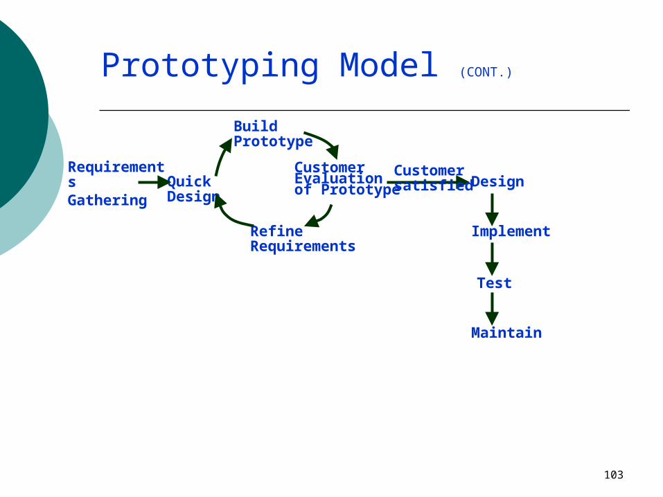
Prototyping Model (CONT.)
The developed prototype is submitted to the customer for his evaluation: Based on the user feedback, requirements
are refined. This cycle continues until the user approves
the prototype. The actual system is developed using
the classical waterfall approach.
103
Prototyping Model (CONT.)
RequirementsGathering Quick Design
Refine Requirements
Build Prototype
Customer Evaluation of Prototype Design
Implement
Test
Maintain
Customer satisfied

104
Evolutionary Model
Evolutionary model (aka successive versions or incremental model): The system is broken down into several
modules which can be incrementally implemented and delivered.
First develop the core modules of the system.
The initial product skeleton is refined into increasing levels of capability: by adding new functionalities in successive
versions.

105
Evolutionary Model (CONT.)
Successive version of the product:functioning systems capable of
performing some useful work. A new release may include new
functionality:also existing functionality in the current release might have been enhanced.

106
Evolutionary Model (CONT.)
AB
C
A AB

107
Advantages of Evolutionary Model
Users get a chance to experiment with a partially developed system: much before the full working version is
released, Helps finding exact user
requirements: much before fully working system is
developed. Core modules get tested thoroughly:
reduces chances of errors in final product.

108
Disadvantages of Evolutionary Model
Often, difficult to subdivide problems into functional units: which can be incrementally
implemented and delivered. evolutionary model is useful for
very large problems, where it is easier to find modules for incremental implementation.

109
Spiral Model
Proposed by Boehm in 1988. Each loop of the spiral represents a
phase of the software process: the innermost loop might be concerned with
system feasibility, the next loop with system requirements
definition, the next one with system design, and so on.
There are no fixed phases in this model, the phases shown in the figure are just examples.

110
Spiral Model (CONT.)
The team must decide: how to structure the project into
phases. Start work using some generic
model: add extra phases
for specific projects or when problems are identified during a project.
Each loop in the spiral is split into four sectors (quadrants).

111
Spiral Model (CONT.)
Determine Objectives
Identify & Resolve Risks
Develop Next Level of Product
Customer Evaluation of Prototype

112
Comparison of Different Life Cycle Models
Iterative waterfall model most widely used model. But, suitable only for well-understood
problems.
Prototype model is suitable for projects not well understood: user requirements technical aspects

113
Comparison of Different Life Cycle Models (CONT.)
Evolutionary model is suitable for large problems: can be decomposed into a set of modules
that can be incrementally implemented, incremental delivery of the system is
acceptable to the customer. The spiral model:
suitable for development of technically challenging software products that are subject to several kinds of risks.

114
Lecture 3

115
Requirements Analysis and Specification

116
Organization of this Lecture
Brief review of previous lectures Introduction Requirements analysis Requirements specification SRS document Decision table Decision tree Summary
117
Requirements Analysis and Specification
Many projects fail: because they start implementing the
system:without determining whether they
are building what the customer really wants.

118
Requirements Analysis and Specification
It is important to learn: requirements analysis and
specification techniques thoroughly.

119
Requirements Analysis and Specification
Goals of requirements analysis and specification phase: fully understand the user requirements remove inconsistencies, anomalies, etc.
from requirements document requirements properly in an SRS
document

120
Requirements Analysis and Specification
Consists of two distinct activities:Requirements Gathering and Analysis
Specification
121
Requirements Analysis
Requirements analysis consists of two main activities:Requirements gatheringAnalysis of the gathered
requirements

122
Requirements Analysis
Analyst gathers requirements through:observation of existing systems,studying existing procedures,discussion with the customer and
end-users,analysis of what needs to be done,
etc.

123
Requirements Gathering (CONT.)
Some desirable attributes of a good system analyst:Good interaction skills, imagination and creativity, experience.

124
Analysis of the Gathered Requirements
After gathering all the requirements: analyze it:
Clearly understand the user requirements, Detect inconsistencies, ambiguities, and
incompleteness.
Incompleteness and inconsistencies: resolved through further discussions with the
end-users and the customers.

125
Software Requirements Specification
Main aim of requirements specification:systematically organize the
requirements arrived during requirements analysis
document requirements properly.
126
Software Requirements Specification
The SRS document is useful in various contexts:statement of user needscontract documentreference documentdefinition for implementation

127
Properties of a good SRS document
It should be concise and at the same time should not be ambiguous.
It should specify what the system must do and not say how to do it.
Easy to change., i.e. it should be well-structured.
It should be consistent. It should be complete.

128
Properties of a good SRS document (cont...)
It should be traceable you should be able to trace which part of the
specification corresponds to which part of the design and code, etc and vice versa.
It should be verifiable e.g. “system should be user friendly” is not verifiable

129
SRS Document (CONT.)
SRS document, normally contains three important parts:functional requirements,nonfunctional requirements,constraints on the system.

130
Functional Requirements
Functional requirements describe: A set of high-level requirementsEach high-level requirement:
takes in some data from the useroutputs some data to the user
Each high-level requirement:might consist of a set of identifiable
functions

131
Functional Requirements
For each high-level requirement:every function is described in terms of
input data set output data setprocessing required to obtain the output
data set from the input data set

132
Nonfunctional Requirements
Characteristics of the system which can not be expressed as functions:
maintainability, portability, usability, etc.

133
Nonfunctional Requirements
Nonfunctional requirements include: reliability issues, performance issues, human-computer interface issues, Interface with other external systems, security, maintainability, etc.

134
Examples of constraints
Hardware to be used, Operating system
or DBMS to be used Capabilities of I/O devices Standards compliance Data representations
by the interfaced system
135
Organization of the SRS Document
Introduction. Functional Requirements Nonfunctional Requirements
External interface requirementsPerformance requirements
Constraints

136
Example Functional Requirements
List all functional requirements with proper numbering.
Req. 1: Once the user selects the “search” option,
he is asked to enter the key words. The system should output details of all books
whose title or author name matches any of the key words entered.
Details include: Title, Author Name, Publisher name, Year of Publication, ISBN Number, Catalog Number, Location in the Library.
137
Example Functional Requirements
Req. 2: When the “renew” option is selected,
the user is asked to enter his membership number and password.
After password validation, the list of the books borrowed by him are
displayed. The user can renew any of the books:
by clicking in the corresponding renew box.

138
Req. 1:
R.1.1: Input: “search” option, Output: user prompted to enter the key words.
R1.2: Input: key words Output: Details of all books whose title or author name
matches any of the key words. Details include: Title, Author Name, Publisher name, Year
of Publication, ISBN Number, Catalog Number, Location in the Library.
Processing: Search the book list for the keywords

139
Req. 2: R2.1:
Input: “renew” option selected, Output: user prompted to enter his membership
number and password. R2.2:
Input: membership number and password Output:
list of the books borrowed by user are displayed. User prompted to enter books to be renewed or
user informed about bad password Processing: Password validation, search books
issued to the user from borrower list and display.

140
Req. 2:
R2.3: Input: user choice for renewal of the
books issued to him through mouse clicks in the corresponding renew box.
Output: Confirmation of the books renewed
Processing: Renew the books selected by the in the borrower list.

141
Summary Requirements analysis and
specification an important phase of software
development: any error in this phase would affect all
subsequent phases of development.
Consists of two different activities: Requirements gathering and analysis Requirements specification

142
Summary The aims of requirements analysis:
Gather all user requirements Clearly understand exact user requirements Remove inconsistencies and incompleteness.
The goal of specification: systematically organize requirements document the requirements in an SRS document.

143
Summary Main components of SRS document:
functional requirements nonfunctional requirements constraints

144
Lecture 4

145
Software Design

146
Organization of this Lecture
Brief review of previous lectures Introduction to software design Goodness of a design Functional Independence Cohesion and Coupling Function-oriented design vs. Object-
oriented design Summary

147
Introduction
Design phase transforms SRS document: into a form easily implementable in
some programming language.
SRS DocumentDesign Activities
Design Documents

148
Items Designed During Design Phase
module structure, control relationship among the modules
call relationship or invocation relationship interface among different modules,
data items exchanged among different modules,
data structures of individual modules, algorithms for individual modules.

149
Module Structure

150
IntroductionA module consists of:
several functions associated data structures.
Data
Functions
D1 ..D2 ..D3 ..
F1 ..F2 ..F3 ..F4 ..F5 ..

151
Introduction
Good software designs:seldom arrived through a single
step procedure:but through a series of steps and
iterations.

152
Introduction
Design activities are usually classified into two stages: preliminary (or high-level) design detailed design.
Meaning and scope of the two stages: vary considerably from one methodology to
another.

153
High-level design
Identify: modules control relationships among modules interfaces among modules.
d1 d2
d3 d1 d4

154
High-level design
The outcome of high-level design: program structure (or software
architecture).

155
High-level Design
Several notations are available to represent high-level design:Usually a tree-like diagram
called structure chart is used. Other notations:
Jackson diagram or Warnier-Orr diagram can also be used.

156
Detailed design
For each module, design:data structurealgorithms
Outcome of detailed design:module specification.

157
A fundamental question:
How to distinguish between good and bad designs? Unless we know what a good
software design is: we can not possibly design one.

158
Good and bad designs
There is no unique way to design a system.
Even using the same design methodology: different engineers can arrive at
very different design solutions.We need to distinguish
between good and bad designs.

159
What Is Good Software Design?
SW Design quality depends on the following characteristics:
1. Modularity
2. Coupling
3. Cohesion
4. Understandability
5. Adaptability & Maintainability
160
Modularity Modularity is a fundamental
attributes of any good design.Decomposition of a problem cleanly
into modules:Modules are almost independent of
each other
161
Modularity If modules are independent:
modules can be understood separately,
reduces the complexity greatly. To understand why this is so,
remember that it is very difficult to break a bunch of sticks but very easy to break the sticks individually.

162
Example of Cleanly and Non-cleanly Decomposed Modules

163
Modularity In technical terms, modules should
display:high cohesionlow coupling.
We will shortly discuss:cohesion and coupling.

164
Cohesion and Coupling
Cohesion is a measure of: functional strength of a module. A cohesive module performs a single
task or function. Coupling between two modules:
a measure of the degree of interdependence or interaction between the two modules.

165
Cohesion and Coupling
A module having high cohesion and low coupling:functionally independent of
other modules: A functionally independent module has minimal interaction with other modules.

166
Functional Independence
Unfortunately, there are no ways:to quantitatively measure the
degree of cohesion and coupling:classification of different kinds of
cohesion and coupling:will give us some idea regarding the
degree of cohesiveness of a module.

167
Classification of Cohesiveness
coincidentallogical
temporal
procedural
sequential
communicational
functional
Degree of cohesion

168
Coincidental cohesion
The module performs a set of tasks:which relate to each other very
loosely, if at all. the module contains a random
collection of functions. functions have been put in the module
out of pure coincidence without any thought or design.
169
Logical cohesion
All elements of the module perform similar operations:e.g. error handling, data input, data
output, etc. An example of logical cohesion:
a set of print functions to generate an output report arranged into a single module.

170
Temporal cohesion
The module contains tasks that are related by the fact: all the tasks must be executed in the same
time span. Example:
The set of functions responsible for initialization, start-up, shut-down of some process,
etc.
171
Procedural cohesion
The set of functions of the module: all part of a procedure
(algorithm)certain sequence of steps have
to be carried out in a certain order for achieving an objective,
e.g. the algorithm for decoding a message.

172
Communicational cohesion
All functions of the module: reference or update the same data
structure, Example:
the set of functions defined on an array or a stack.

173
Sequential cohesion
Elements of a module form different parts of a sequence, output from one element of the
sequence is input to the next. Example:
sort
search
display

174
Functional cohesion
Different elements of a module cooperate:to achieve a single function, e.g. managing an employee's
pay-roll. When a module displays
functional cohesion, we can describe the function
using a single sentence.

175
Determining Cohesiveness
Write down a sentence to describe the function of the module If the sentence is compound,
it has a sequential or communicational cohesion.
If it has words like “first”, “next”, “after”, “then”, etc. it has sequential or temporal cohesion.
If it has words like initialize, it probably has temporal cohesion.

176
Coupling
Coupling indicates: how closely two modules
interact or how interdependent they are.
The degree of coupling between two modules depends on their interface complexity.

177
Coupling
There are no ways to precisely determine coupling between two modules: classification of different types of
coupling will help us to approximately estimate the degree of coupling between two modules.
Five types of coupling can exist between any two modules.
178
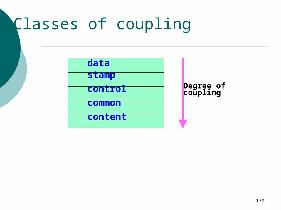
Classes of coupling
content
common
stamp
control
data
Degree of coupling

179
Data couplingTwo modules are data
coupled, if they communicate via a
parameter: an elementary data item, e.g an integer, a float, a character, etc.
The data item should be problem related:not used for control purpose.

180
Stamp coupling
Two modules are stamp coupled, if they communicate via a
composite data item such as a record in PASCAL or a structure in C.
181
Control coupling
Data from one module is used to direct order of instruction execution in
another. Example of control coupling:
a flag set in one module and tested in another module.

182
Common Coupling
Two modules are common coupled, if they share some global data.
183
Content coupling
Content coupling exists between two modules: if they share code, e.g, branching from one module into
another module. The degree of coupling increases
from data coupling to content coupling.

184
Design Approaches
Two fundamentally different software design approaches:Function-oriented designObject-oriented design

185
Design Approaches
These two design approaches are radically different. However, are complementary
rather than competing techniques.Each technique is applicable at
different stages of the design process.

186
Function-Oriented Design
A system is looked upon as somethingthat performs a set of functions.
Starting at this high-level view of the system:each function is successively refined
into more detailed functions.Functions are mapped to a module
structure.
187
Example
The function create-new-library- member:creates the record for a new
member, assigns a unique membership
numberprints a bill towards the
membership

188
Example
Create-library-member function consists of the following sub-functions: assign-membership-numbercreate-member-recordprint-bill

189
Function-Oriented Design
Each subfunction: split into more detailed subfunctions and so on.

190
Function-Oriented Design
The system state is centralized:accessible to different functions,
member-records:available for reference and updation
to several functions:create-new-memberdelete-memberupdate-member-record

191
Function-Oriented Design
Several function-oriented design approaches have been developed:Structured design (Constantine and
Yourdon, 1979) Jackson's structured design (Jackson,
1975) Warnier-Orr methodology Wirth's step-wise refinement Hatley and Pirbhai's Methodology

192
Object-Oriented Design
System is viewed as a collection of objects (i.e. entities).
System state is decentralized among the objects:each object manages its own
state information.

193
Object-Oriented Design Example
Library Automation Software:each library member is a separate object with its own data and functions.
Functions defined for one object:cannot directly refer to or change data of other objects.
194
Object-Oriented Design
Objects have their own internal data: defines their state.
Similar objects constitute a class. each object is a member of some
class. Classes may inherit features
from a super class. Conceptually, objects
communicate by message passing.

195
Object-Oriented versus Function-Oriented Design
Unlike function-oriented design, in OOD the basic abstraction is
not functions such as “sort”, “display”, “track”, etc.,
but real-world entities such as “employee”, “picture”, “machine”, “radar system”, etc.

196
Object-Oriented versus Function-Oriented Design
In OOD: software is not developed by
designing functions such as:update-employee-record, get-employee-address, etc.
but by designing objects such as:employees, departments, etc.
197
Object-Oriented versus Function-Oriented Design
Grady Booch sums up this fundamental difference saying:“Identify verbs if you are after procedural design and nouns if you are after object-oriented design.”

198
Object-Oriented versus Function-Oriented Design
In OOD:state information is not shared in a centralized data.
but is distributed among the objects of the system.

199
Object-Oriented versus Function-Oriented Design
Function-oriented techniques group functions together if:as a group, they constitute a higher
level function. On the other hand, object-oriented
techniques group functions together: on the basis of the data they operate
on.

200
Object-Oriented versus Function-Oriented Design
To illustrate the differences between object-oriented and function-oriented design approaches, let us consider an example --- An automated fire-alarm system for a
large building.

201
Fire-Alarm System:
We need to develop a computerized fire alarm system for a large multi-storied building:There are 80 floors and 1000
rooms in the building.
202
Fire-Alarm System:
Different rooms of the building:fitted with smoke detectors
and fire alarms. The fire alarm system would
monitor:status of the smoke detectors.

203
Fire-Alarm System
Whenever a fire condition is reported by any smoke detector: the fire alarm system should:
determine the location from which the fire condition was reported
sound the alarms in the neighboring locations.

204
Fire-Alarm System
The fire alarm system should: flash an alarm message on the
computer console: fire fighting personnel man the console round the clock.

205
Fire-Alarm System
After a fire condition has been successfully handled, the fire alarm system should
let fire fighting personnel reset the alarms.

206
Function-Oriented Approach:
/* Global data (system state) accessible by various functions */BOOL detector_status[1000];int detector_locs[1000];BOOL alarm-status[1000]; /* alarm activated when status set */int alarm_locs[1000]; /* room number where alarm is located */int neighbor-alarms[1000][10];/*each detector has at most*/ /* 10 neighboring alarm locations */
The functions which operate on the system state: interrogate_detectors(); get_detector_location(); determine_neighbor(); ring_alarm(); reset_alarm(); report_fire_location();
207
Object-Oriented Approach:
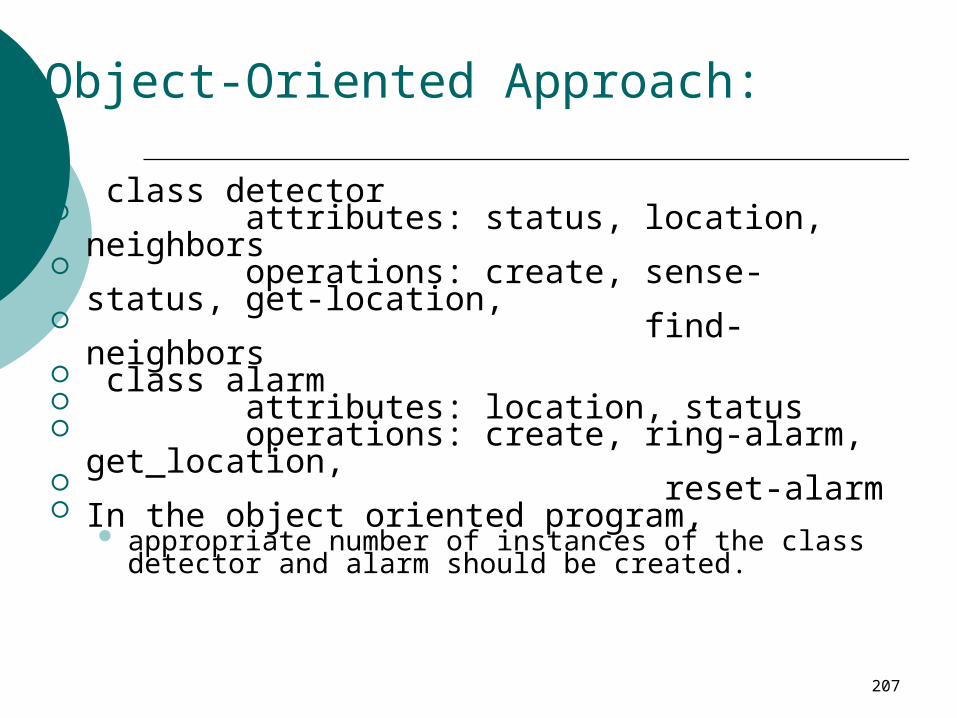
class detector attributes: status, location, neighbors operations: create, sense-status, get-
location, find-neighbors class alarm attributes: location, status operations: create, ring-alarm,
get_location, reset-alarm In the object oriented program,
appropriate number of instances of the class detector and alarm should be created.

208
Object-Oriented versus Function-Oriented Design
In the function-oriented program :the system state is centralizedseveral functions accessing these
data are defined. In the object oriented program,
the state information is distributed among various sensor and alarm objects.

209
Object-Oriented versus Function-Oriented Design
Use OOD to design the classes:then applies top-down function
oriented techniques to design the internal methods of classes.

210
Object-Oriented versus Function-Oriented Design
Though outwardly a system may appear to have been developed in an object oriented fashion, but inside each class there is a small
hierarchy of functions designed in a top-down manner.
211
Summary We started with an overview of:
activities undertaken during the software design phase.
We identified: the information need to be produced
at the end of the design phase:so that the design can be easily
implemented using a programming language.

212
Summary
We characterized the features of a good software design by introducing the concepts of:cohesion, coupling, etc.

213
Summary
We classified different types of cohesion and coupling:enables us to approximately determine the cohesion and coupling existing in a design.

214
Summary
Two fundamentally different approaches to software design:function-oriented approachobject-oriented approach

215
Summary
We looked at the essential philosophy behind these two approaches these two approaches are not
competing but complementary approaches.
216
The End
THANK YOU ALL FOR YOUR TIME AND EFFORT


