44
Lecture 14: Real-Time Ray Tracing Kayvon Fatahalian CMU 15-869: Graphics and Imaging Architectures (Fall 2011)

Lecture 14:Real-Time Ray Tracing
Kayvon FatahalianCMU 15-869: Graphics and Imaging Architectures (Fall 2011)

Kayvon Fatahalian, Graphics and Imaging Architectures (CMU 15-869, Fall 2011)
Recent push towards real-time ray tracing
Image credit: NVIDIA (this image can be rendered at “interactive rates” on NVIDIA Fermi: not real-time yet)

Kayvon Fatahalian, Graphics and Imaging Architectures (CMU 15-869, Fall 2011)
Visibility▪ Determine which scene geometry contributes to the appearance
of which screen pixels▪ Can be thought of as a problem of computing interacting pairs▪ Can be thought of as a search problem- Given polygon, !nd pixel(s) it contributes to
- Given pixel, !nd triangle(s) that contribute to it
Screen
Camera

Kayvon Fatahalian, Graphics and Imaging Architectures (CMU 15-869, Fall 2011)
▪ Commonly solved via point sampling- Rasterization:
- What scene geometry covers each visibility sample?- Coverage (what triangles cover) + occlusion (closest covering triangle)
- Ray tracing formulation:- Sample → ray in 3D- What scene geometry is intersected by each ray?- Which intersection is closest?
Screen
Camera
Visibility

Kayvon Fatahalian, Graphics and Imaging Architectures (CMU 15-869, Fall 2011)
Ray tracing▪ Perform ray-scene visibility queries▪ Given ray (origin, direction), !nd what scene object(s) are
intersected (“hit”) by ray, optionally determine point of intersection
Camera

Kayvon Fatahalian, Graphics and Imaging Architectures (CMU 15-869, Fall 2011)
Sampling light paths
Image credit: Wann Jensen, Hanrahan

Kayvon Fatahalian, Graphics and Imaging Architectures (CMU 15-869, Fall 2011)
Types of rays
▪ Camera (a.k.a., eye rays, primary rays)- Common origin, similar direction
▪ Shadow- Point source: common destination, similar direction
- Area source: similar destination, similar direction (ray “coherence” breaks down as light source increases in size: e.g., consider entire sky as an area light source)
▪ Indirect illumination- Mirror surface
- Glossy surface
- Diffuse surface Mirror Surface
Glossy Surface
Diffuse Surface
Point lightArea Light
Kayvon Fatahalian, Graphics and Imaging Architectures (CMU 15-869, Fall 2011)
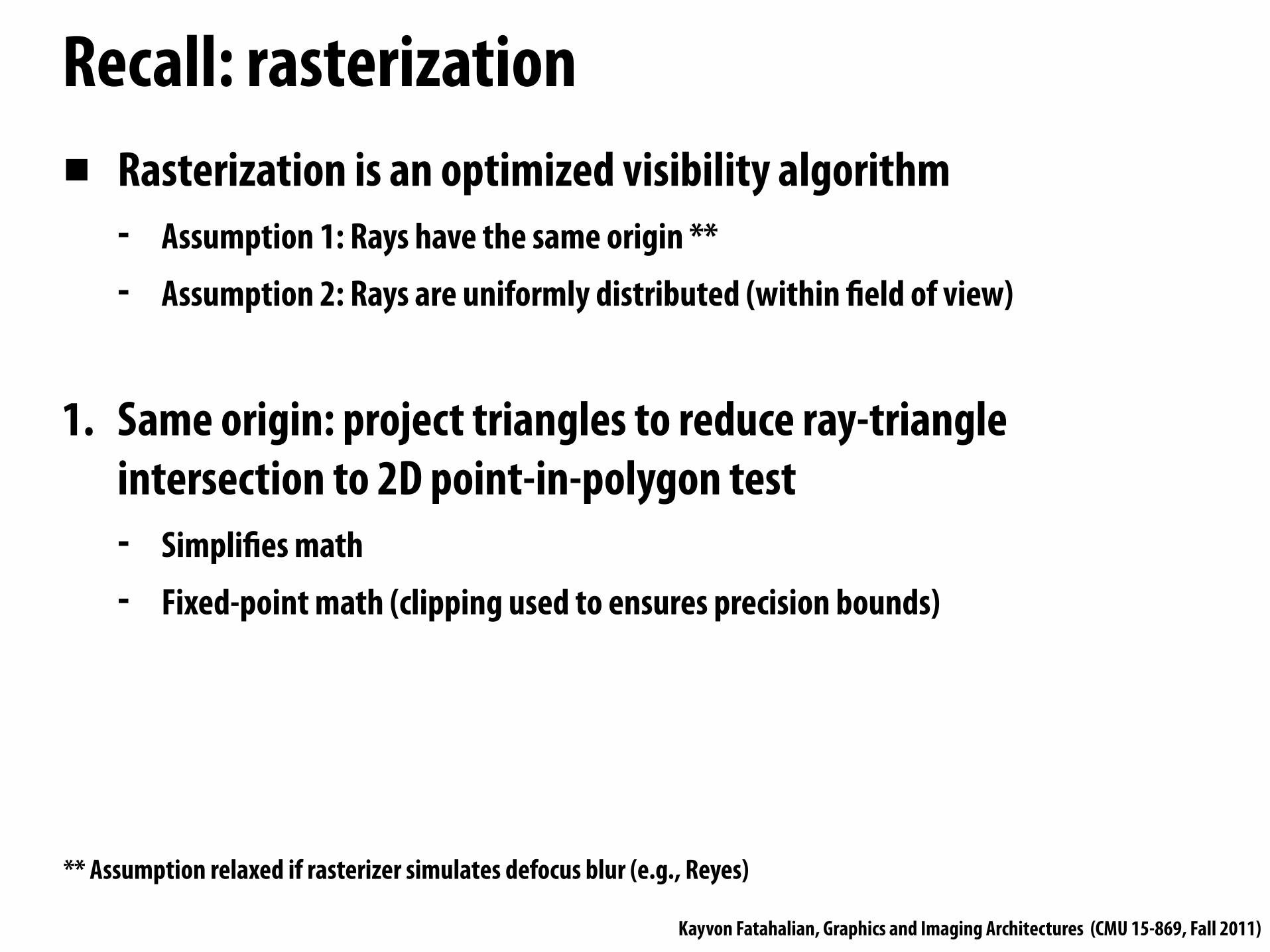
Recall: rasterization▪ Rasterization is an optimized visibility algorithm
- Assumption 1: Rays have the same origin **- Assumption 2: Rays are uniformly distributed (within !eld of view)
1. Same origin: project triangles to reduce ray-triangle intersection to 2D point-in-polygon test- Simpli!es math- Fixed-point math (clipping used to ensures precision bounds)
** Assumption relaxed if rasterizer simulates defocus blur (e.g., Reyes)

Kayvon Fatahalian, Graphics and Imaging Architectures (CMU 15-869, Fall 2011)
Rasterization: ray origin need not be camera position
Shadow mapping: place origin at shadowed light source
Image credits: Segal et al. 92, Cass Everitt
Shadow rays
Shadow map: stores shadow ray results

Kayvon Fatahalian, Graphics and Imaging Architectures (CMU 15-869, Fall 2011)
Shadow map undersampling
Image credit: Johnson et al. TOG 2005
Shadows computed using shadow map
Correct hard shadows

Kayvon Fatahalian, Graphics and Imaging Architectures (CMU 15-869, Fall 2011)
Rasterization: ray origin need not be camera positionEnvironment mapping:place ray origin at re"ective object
Image credit: http://en.wikipedia.org/wiki/Cube_mapping
Scene rendered 6 times, with ray origin at center of re"ective box(produces cube-map)
Center of projection
Cube map:stores results of approximate mirror re"ection rays
(Question: how can a glossy surface be rendered using the cube-map)
Kayvon Fatahalian, Graphics and Imaging Architectures (CMU 15-869, Fall 2011)
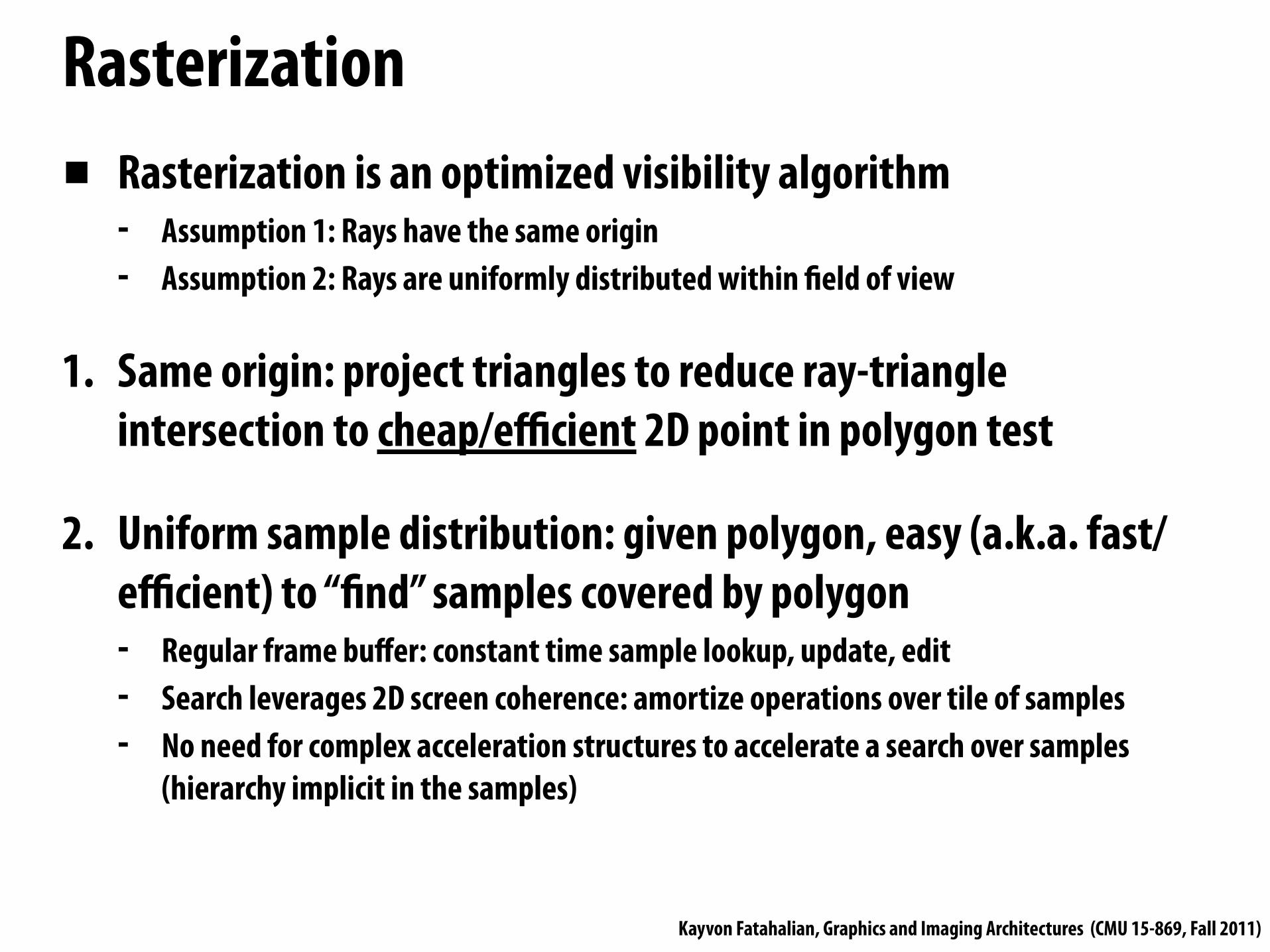
Rasterization▪ Rasterization is an optimized visibility algorithm
- Assumption 1: Rays have the same origin- Assumption 2: Rays are uniformly distributed within #eld of view
1. Same origin: project triangles to reduce ray-triangle intersection to cheap/efficient 2D point in polygon test
2. Uniform sample distribution: given polygon, easy (a.k.a. fast/efficient) to “!nd” samples covered by polygon- Regular frame buffer: constant time sample lookup, update, edit - Search leverages 2D screen coherence: amortize operations over tile of samples- No need for complex acceleration structures to accelerate a search over samples
(hierarchy implicit in the samples)

Kayvon Fatahalian, Graphics and Imaging Architectures (CMU 15-869, Fall 2011)
Rasterization: performance▪ Frame-buffer: !xed number of samples (determined by screen
resolution, sampling rate) and common sample representation- Efficient to !nd samples covered by polygon (highly optimized !xed-function
implementations of both coverage computation and frame-buffer update)
▪ Approach: stream over geometry (regular/predictable), directly access frame-buffer samples- Unpredictable access to samples, but manageable (see properties above, and
previous lectures about pipeline sorting and color/z-buffer caching/compression)
▪ Scales to high scene complexity

Kayvon Fatahalian, Graphics and Imaging Architectures (CMU 15-869, Fall 2011)
Review: Ray Tracing 101

Kayvon Fatahalian, Graphics and Imaging Architectures (CMU 15-869, Fall 2011)
ProblemGiven ray, !nd !rst intersection with scene geometry **
** Simpler, but common query: determine if any intersection exists

Kayvon Fatahalian, Graphics and Imaging Architectures (CMU 15-869, Fall 2011)
Acceleration structures Preprocess scene to build data structure to accelerate ray-scene visibility queries
e.g., bounding volume hierarchy (BVH)Idea: nodes group objects with spatial proximityAdapts to non-uniform density of scene objects
Image credit: Wald et al. TOG 2004
Three different bounding volume hierarchies for the same scene

Kayvon Fatahalian, Graphics and Imaging Architectures (CMU 15-869, Fall 2011)
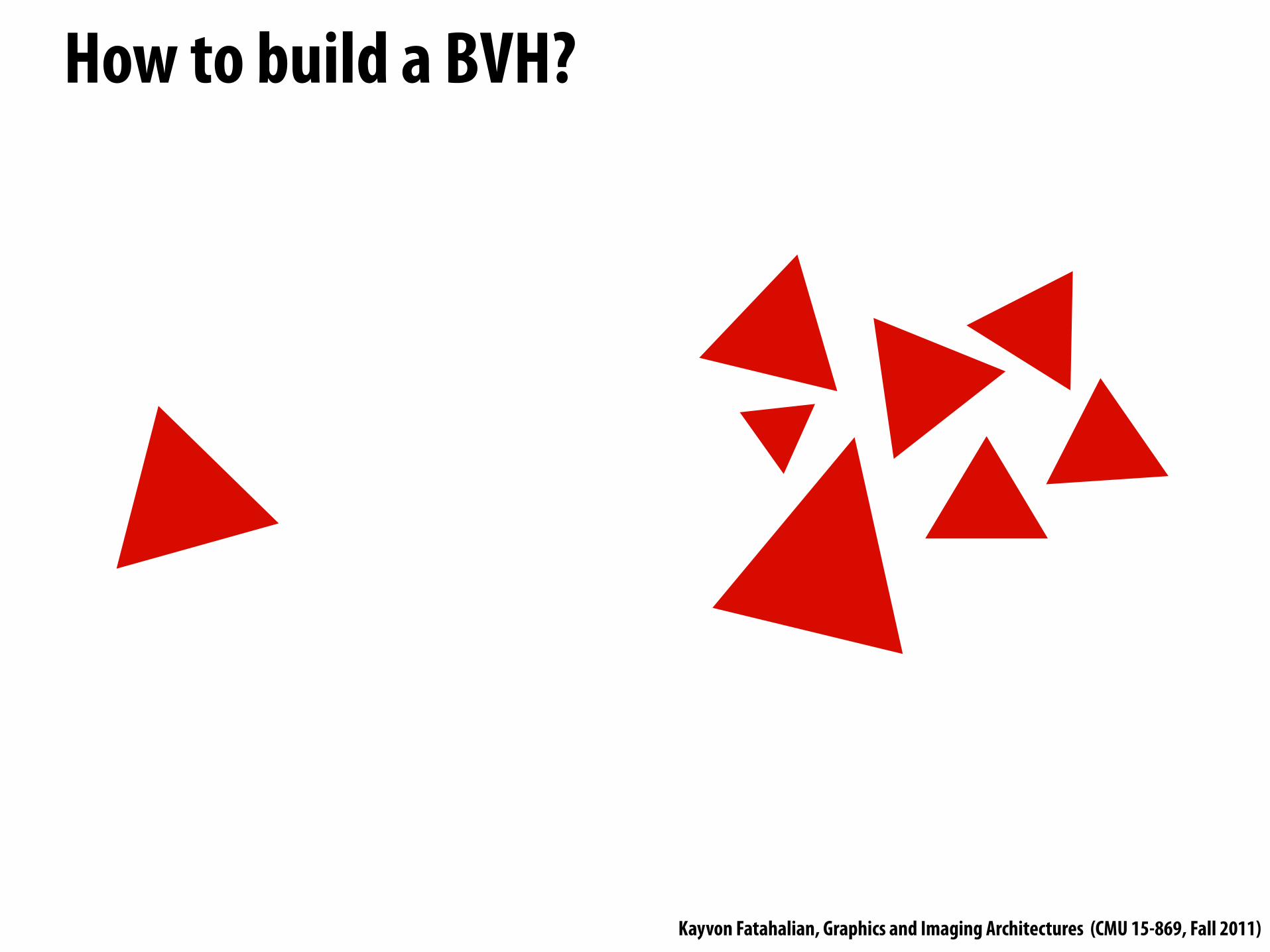
How to build a BVH?
Kayvon Fatahalian, Graphics and Imaging Architectures (CMU 15-869, Fall 2011)
How to build a BVH?
Kayvon Fatahalian, Graphics and Imaging Architectures (CMU 15-869, Fall 2011)
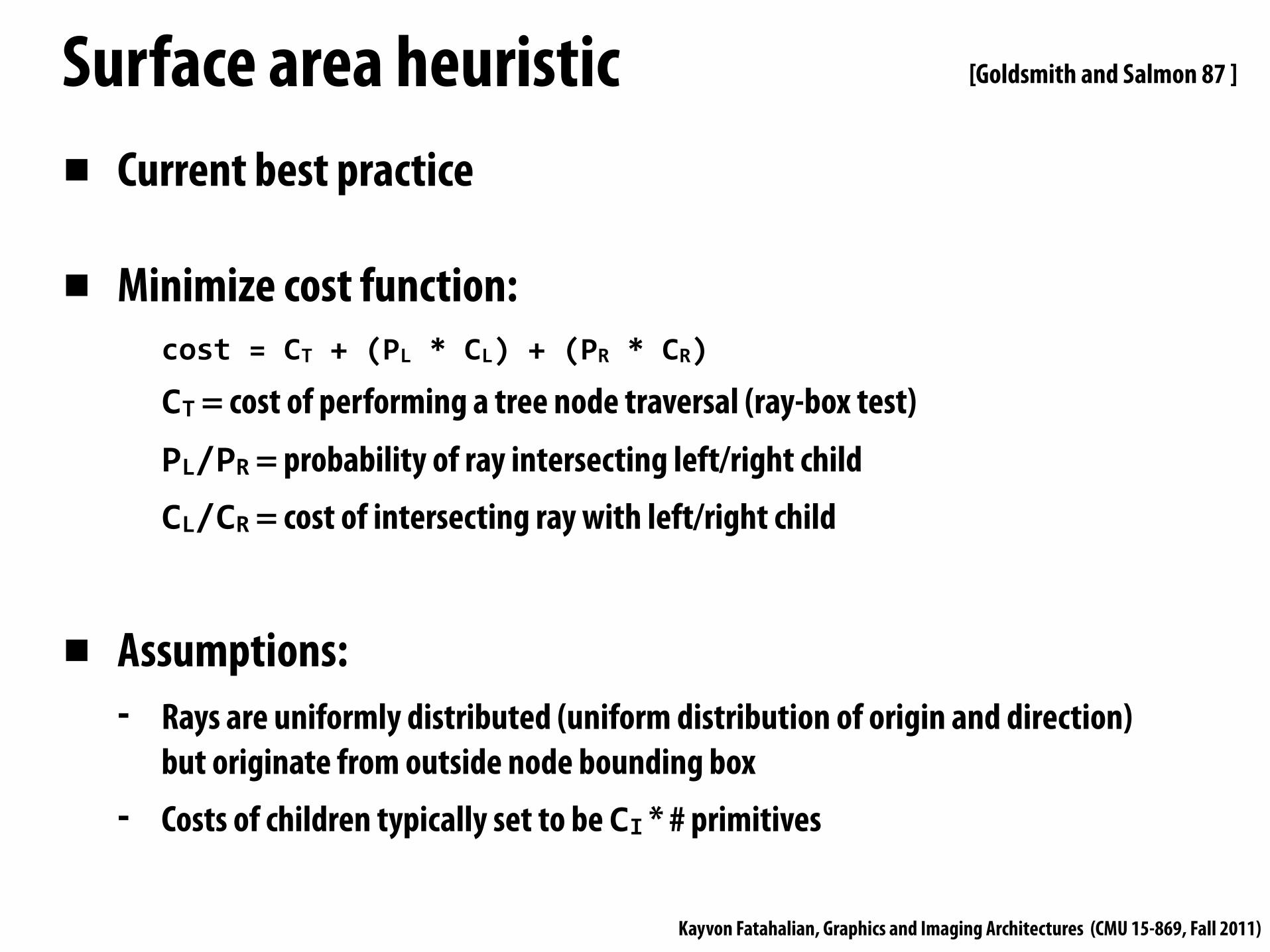
Surface area heuristic▪ Current best practice
▪ Minimize cost function:cost = CT + (PL * CL) + (PR * CR)
CT = cost of performing a tree node traversal (ray-box test)PL/PR = probability of ray intersecting left/right childCL/CR = cost of intersecting ray with left/right child
▪ Assumptions:- Rays are uniformly distributed (uniform distribution of origin and direction)
but originate from outside node bounding box- Costs of children typically set to be CI * # primitives
[Goldsmith and Salmon 87 ]

Kayvon Fatahalian, Graphics and Imaging Architectures (CMU 15-869, Fall 2011)
Simple ray tracer (using BVH)// stores information about closest hit found so farstruct ClosestHitInfo { Primitive primitive; float distance;};
trace(Ray ray, BVHNode node, ClosestHitInfo hitInfo){ if (!intersect(ray, node.bbox) || (closest point on box is farther than hitInfo.distance)) return;
if (node.leaf) { for (each primitive in node) { (hit, distance) = intersect(ray, primitive); if (hit && distance < hitInfo.distance) { hitInfo.primitive = primitive; hitInfo.distance = distance; } } } else {
trace(ray, node.leftChild, hitInfo); trace(ray, node.rightChild, hitInfo); }}

Kayvon Fatahalian, Graphics and Imaging Architectures (CMU 15-869, Fall 2011)
Making Ray Tracing Run Fast
Simpli#cations in today’s discussion:Will not discuss how to make acceleration structure build fast (active research topic)
Scene acceleration structure is read-only: no on-demand build, no on-demand tessellation
Kayvon Fatahalian, Graphics and Imaging Architectures (CMU 15-869, Fall 2011)
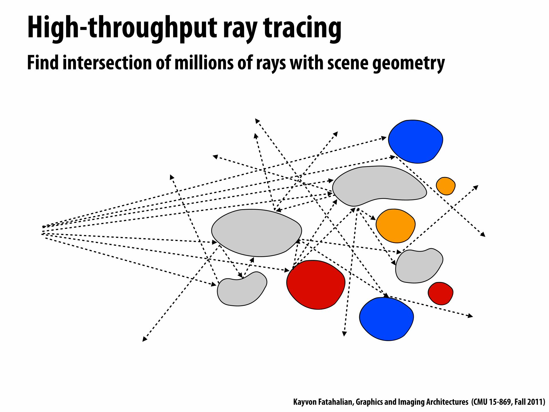
High-throughput ray tracingFind intersection of millions of rays with scene geometry

Kayvon Fatahalian, Graphics and Imaging Architectures (CMU 15-869, Fall 2011)
High-throughput ray tracing
▪ Work efficiency of algorithms- High quality acceleration structures (minimize ray-box, ray-primitive tests)- Smart traversal algorithms (early termination, etc.)
▪ Parallelism: multi-core, SIMD execution efficiency
▪ Bandwidth efficiency (caching, memory access characteristics)
Same issues we’ve talked about all class!Tension between employing most work-efficient algorithms, and using
available execution and bandwidth resources well.

Kayvon Fatahalian, Graphics and Imaging Architectures (CMU 15-869, Fall 2011)
Parallelize across rays▪ Simultaneously intersect multiple rays with scene
▪ Method 1: SPMD style - Each program instance intersects one ray against scene BVH
(programmer writes single ray algorithm)- Recall previous homework assignment (1D ray tracing)
- SIMD efficient when program instances execute same instructions- Bandwidth efficient when rays in a SIMD block (“warp”) visit same BVH nodes - Will discuss further after reading Aila et al. 2009
▪ Method 2: ray packets

Kayvon Fatahalian, Graphics and Imaging Architectures (CMU 15-869, Fall 2011)
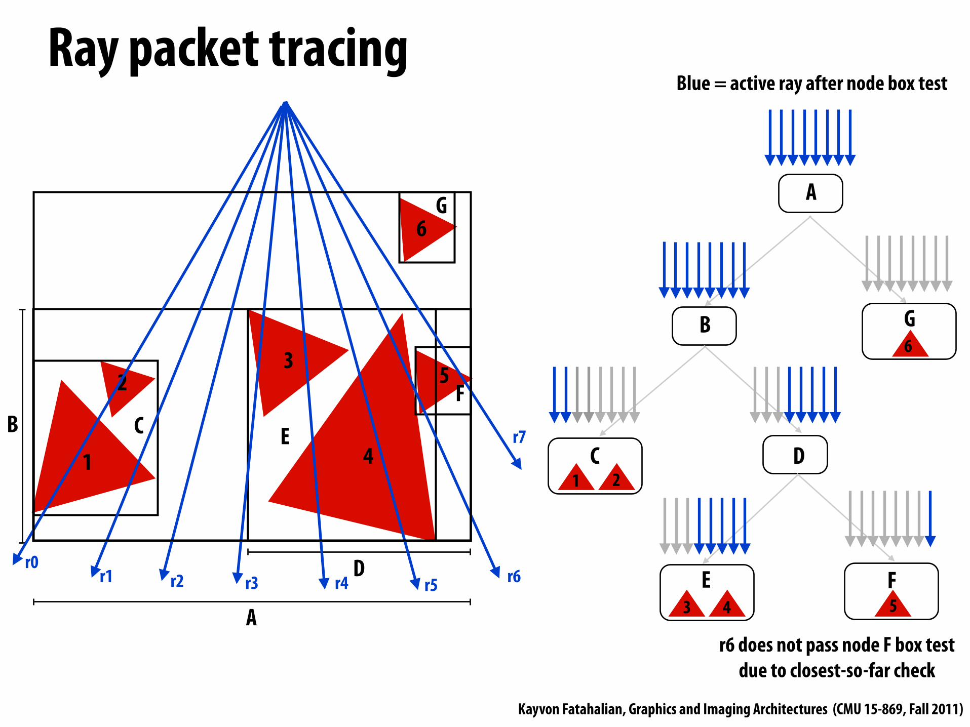
Ray packet tracingProgram explicitly intersects a collection of rays against BVH at once RayPacket{ Ray rays[PACKET_SIZE]; bool active[PACKET_SIZE];};
trace(RayPacket rays, BVHNode node, ClosestHitInfo packetHitInfo){ if (!ANY_ACTIVE_intersect(rays, node.bbox) || (closest point on box (for all active rays) is farther than hitInfo.distance)) return;
update packet active mask
if (node.leaf) { for (each primitive in node) { for (each ACTIVE ray r in packet) { (hit, distance) = intersect(ray, primitive); if (hit && distance < hitInfo.distance) { hitInfo[r].primitive = primitive; hitInfo[r].distance = distance; } } } } else { trace(rays, node.leftChild, hitInfo); trace(rays, node.rightChild, hitInfo); }}
[Wald et al. 2001]
Kayvon Fatahalian, Graphics and Imaging Architectures (CMU 15-869, Fall 2011)
Ray packet tracing
1
2 3
4
5
C E
F
D
B
B
C D
E F
1 2
3 4 5
6
G6
A
A
G
Blue = active ray after node box test
r0 r1 r2 r3 r4 r5 r6
r7
r6 does not pass node F box test due to closest-so-far check

Kayvon Fatahalian, Graphics and Imaging Architectures (CMU 15-869, Fall 2011)
Advantages of packets▪ SIMD execution
- One vector lane per ray
▪ Amortize fetch: all rays in packet visit node at same time- Load BVH node once for all rays in packet- Note: value to making packets much bigger than SIMD width!- Contrast with SPMD approach
▪ Amortize work (packets are hierarchies over rays)- Use interval arithmetic to conservatively test entire set of rays against node bbox
(e.g., think of a packet as a beam)- Further optimizations possible when all rays share origin - Note: value to making packets much bigger than SIMD width!

Kayvon Fatahalian, Graphics and Imaging Architectures (CMU 15-869, Fall 2011)
Disadvantages of packets
B
C D
E F
1 2
3 4 5
G6
A
Blue = active ray after node box test
▪ If any ray must visit a node, it drags all rays in the packet along with it(note contrast with SPMD version: each ray only visits BVH nodes it is required to)
▪ Loss of efficiency: node traversal, intersection, etc. amortized over less than a packet’s worth of rays
▪ Not all SIMD lanes doing useful work
Both packet tracing and SPMD ray tracing suffer from decreased SIMD and cache efficiency when rays traverse the BVH differently... but take a moment to think about why (the reasons are different).

Kayvon Fatahalian, Graphics and Imaging Architectures (CMU 15-869, Fall 2011)
Ray packet tracing: incoherent rays
1
2 3
4
5
C E
F
D
B
B
C D
E F
1 2
3 4 5
6
G6
A
A
G
Blue = active ray after node box test
r0
r1
r3
r3
r4
r5
r6
r7
When rays are incoherent, bene#t of packets can decrease signi#cantly. This example: packet visits all tree nodes. (All rays visit all tree nodes)

Kayvon Fatahalian, Graphics and Imaging Architectures (CMU 15-869, Fall 2011)
Incoherence is a property of both the rays and the scene
Random rays are “coherent” with respect to the BVH if the scene is one big triangle!

Kayvon Fatahalian, Graphics and Imaging Architectures (CMU 15-869, Fall 2011)
Incoherence is a property of both the rays and the scene
Camera rays become “incoherent” with respect to lower nodes in the BVH if a scene is overly detailed
(note importance of geometric level of detail)

Kayvon Fatahalian, Graphics and Imaging Architectures (CMU 15-869, Fall 2011)
Improving packet tracing with ray reordering
16-ray packet: 7 of 16 rays active
Reorder raysRecompute intervals/bounds for active rays
Continue tracing with 8-ray packet: 7 of 8 rays active
Example: 8-wide SIMD processor, 16-ray packets(2 SIMD instructions required to perform operation on all rays in packet)
Idea: when packet utilization drops below threshold, resort rays and continue with smaller packet- Increases SIMD utilization- Still loses amortization bene!ts of large packets
[Boulos et al. 2008]

Kayvon Fatahalian, Graphics and Imaging Architectures (CMU 15-869, Fall 2011)
Improving packet tracing with ray reordering
10-18% speedup over standard packet tracing for glossy re$ection rays 25-50% speedup for 2-bounce diffuse interre$ection rays(4-wide SSE implementation)
Idea: when packet utilization drops below threshold, resort rays and continue with smaller packet- Increases SIMD utilization- Still loses amortization bene!ts of large packets
Bene!t of higher utilization/tighter packet bounds must overcome overhead of reordering operation
[Boulos et al. 2008]

Kayvon Fatahalian, Graphics and Imaging Architectures (CMU 15-869, Fall 2011)
Giving up on packets▪ Even with reordering, ray coherence during BVH traversal will diminish
- Little bene!t to packets (can decrease performance compared to single ray code)
▪ Idea: exploit SIMD execution within single ray-BVH intersection query- Interior: use wider-branching BVH
(test single ray against multiple node bboxes in parallel)- Branching factor 4 has similar efficiency to branching factor 2- Branching factor 16 exhibits signi!cant reduction in efficiency
- Leaf: test ray against multiple triangles in parallel
[Wald et al. 2008]

Kayvon Fatahalian, Graphics and Imaging Architectures (CMU 15-869, Fall 2011)
Giving up on packets
▪ Even with reordering, ray coherence during BVH traversal will diminish- Little bene!t to packets (can decrease performance compared to single ray code)
▪ Idea: exploit SIMD execution within single ray-BVH intersection query- Interior: use wider-branching BVH- Leaf: test ray against multiple triangles in parallel
▪ SIMD efficiency independent of ray coherence
▪ But no work/bandwidth reduction due to amortization across rays- Weren’t getting much bene!t from packets of incoherent rays anyway

Kayvon Fatahalian, Graphics and Imaging Architectures (CMU 15-869, Fall 2011)
Packet tracing best practices
▪ Use large packets for higher levels of BVH- Ray coherence always high at the top of the tree
▪ Switch to single ray (intra-ray SIMD) when packet utilization drops below threshold- For wide SIMD machine, a single branching-factor 4 BVH works well for both
packet and single ray traversal
▪ Can use packet reordering to postpone time of switch- Reordering allows packets to provide bene!t deeper into tree
[Benthin et al. 2011]
[Wald et al. 2007]
[Boulos et al. 2008]
Kayvon Fatahalian, Graphics and Imaging Architectures (CMU 15-869, Fall 2011)
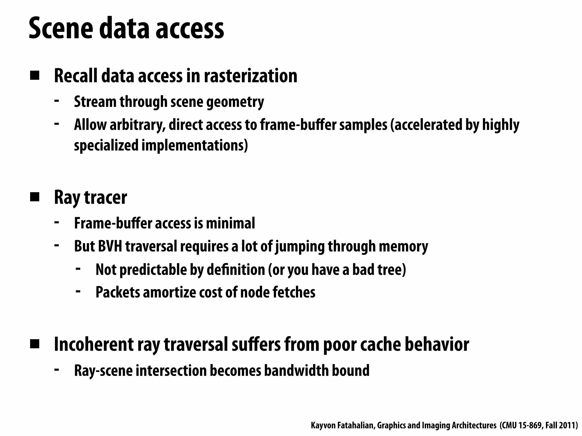
Scene data access▪ Recall data access in rasterization
- Stream through scene geometry- Allow arbitrary, direct access to frame-buffer samples (accelerated by highly
specialized implementations)
▪ Ray tracer- Frame-buffer access is minimal- But BVH traversal requires a lot of jumping through memory
- Not predictable by de!nition (or you have a bad tree)- Packets amortize cost of node fetches
▪ Incoherent ray traversal suffers from poor cache behavior- Ray-scene intersection becomes bandwidth bound

Kayvon Fatahalian, Graphics and Imaging Architectures (CMU 15-869, Fall 2011)
Global ray reorderingIdea: batch up rays in the same part of the scene. Process these rays together to increase locality
Partition BVH into treelets(treelets sized for L1 or L2 cache)
1. When ray (or packet) enters treelet, add rays to treelet queue
2. When treelet queue is sufficiently deep, intersect enqueued rays with treelet
[Phar 1997, Navratil 07, Alia 10]
[Phar 1997, Navratil 07, Alia 10]Lots of academic work + some industry attemptsStill not common in major ray tracing implementations

Kayvon Fatahalian, Graphics and Imaging Architectures (CMU 15-869, Fall 2011)
Summary

Kayvon Fatahalian, Graphics and Imaging Architectures (CMU 15-869, Fall 2011)
Not discussed todayA practical, efficient real-time ray tracing system will also need to solve these important challenges
1. Building the BVH efficiently- Rebuild or update each frame as scene changes?
2. On-demand geometry: tessellation- Intersection modi!es BVH (not so embarrassingly parallel anymore)- How to determine level-of-detail?
3. Efficiently shading ray hits- What to do when rays in a packet hits surfaces with different shaders?

Kayvon Fatahalian, Graphics and Imaging Architectures (CMU 15-869, Fall 2011)
Summary▪ Visibility: determine which scene geometry contributes to the
appearance of which screen pixels- “Basic” rasterization: given polygon, !nd samples(s) it overlaps- “Basic” ray tracing: given ray, !nd triangle(s) that it intersects
▪ In practice, not as different as you might think
▪ Just different ways to solve the problem of !nding interacting pairs between two hierarchies **- Hierarchy over point samples- Hierarchy over geometry
** A great analogy is collision detection (credit Tim Foley)

Kayvon Fatahalian, Graphics and Imaging Architectures (CMU 15-869, Fall 2011)
Consider performant, modern solutions for primary-ray visibility▪ “Rasterizer”
- Hierarchical rasterization (uniform grid over samples)- Hierarchical depth culling (quad-tree over samples)- Application scene graph, hierarchy over geometry
- Modern games perform conservative coarse culling, only submit potentially visible geometry to the rendering pipeline(in practice, rasterization not linear in amount of geometry in scene)
▪ “Ray tracer”- BVH: hierarchy over geometry- Packets form hierarchy over samples (akin to frame buffer tiles). Breaking packets
into small packets during traversal adds complexity to the hierarchy- Wide packet traversal, high-branching BVH: decrease work efficiency for better
machine utilization(in practice, signi#cant constants in front of that lg(N))

Kayvon Fatahalian, Graphics and Imaging Architectures (CMU 15-869, Fall 2011)
Trends: ray tracing in #lm
▪ Reyes algorithm still predominant solution for primary ray visibility
▪ Re"ections, indirect illumination, ambient occlusion, some shadows often computed via ray tracing
▪ Sony Pictures Imageworks now uses only ray tracing for all #lms- Arnold renderer has replaced Renderman at Sony
▪ Complex reasons motivate shift to ray tracing- More than just performance (artist time,
production cost, etc.)Image Credit: Sony (Cloudy With a Chance of Meatballs)
Image Credit: Pixar (Cars)
Image Credit: Blue Sky

Kayvon Fatahalian, Graphics and Imaging Architectures (CMU 15-869, Fall 2011)
Readings▪ For next time:
- T. Aila and S. Laine, Understanding the Efficiency of Ray Traversal on GPUs. High Performance Graphics 2009
▪ Lots of supplemental ray tracing readings posted on the web site


