40
CPE 487: Digital System Design Spring 2018 Lecture 2 Digital Logic Basics Bryan Ackland Department of Electrical and Computer Engineering Stevens Institute of Technology Hoboken, NJ 07030

CPE 487: Digital System DesignSpring 2018
Lecture 2Digital Logic Basics
1
Bryan AcklandDepartment of Electrical and Computer Engineering
Stevens Institute of TechnologyHoboken, NJ 07030

Digital Abstraction
• Most physical variables are continuous– voltage on a wire– frequency of an oscillation– position of a mass
• Computation on continuous variables subject to noise and distortion• any computation will have finite error• errors will accumulate
• Digital abstraction considers discrete subset of values• output can be “restored” to correct value• error free (with very high probability)
2

Digital Discipline: Binary Values
• Early computing engines used multi-value digital variables– Babbage engine used gears with 10 different positions– Simplified base10 arithmetic
• Very difficult to build electronic circuits that restore to multiple (>2) discrete values
• Very easy to build circuits that restore to two values• Use two discrete (binary) values: 0 and 1
3
Transfer function of a simple CMOS inverter:
input
output

Digital Discipline: Binary Values
• Binary signals can be used to represent logical values:– 0 = FALSE 1 = TRUE
• Binary signals can be used to represent numerical values:– using base2 representation– each binary signal represents one binary digit (bit)
• Binary signals can be used to represent any other variable that can only take on one of two different values– e.g. black/white, on/off, up/down
• In digital electronic circuits:– 0 is usually low voltage (ground, VSS, 0 volts)– 1 is usually high voltage (power supply, VDD, 3.3 volts)
• Beauty of (binary) digital abstraction is that the designer does not need to know the (physical) implementation details– can just focus on 0’s and 1’s
4
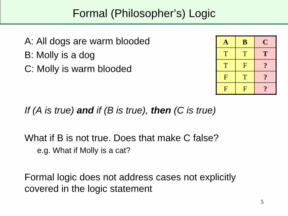
Formal (Philosopher’s) Logic
A: All dogs are warm bloodedB: Molly is a dogC: Molly is warm blooded
If (A is true) and if (B is true), then (C is true)
What if B is not true. Does that make C false?e.g. What if Molly is a cat?
Formal logic does not address cases not explicitly covered in the logic statement
5
A B CT T TT F ?F T ?F F ?
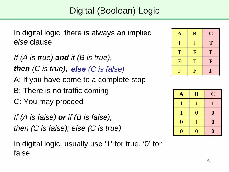
Digital (Boolean) Logic
In digital logic, there is always an implied else clause
If (A is true) and if (B is true),then (C is true); A: If you have come to a complete stopB: There is no traffic comingC: You may proceed
If (A is false) or if (B is false),then (C is false); else (C is true)
In digital logic, usually use ‘1’ for true, ‘0’ for false
6
A B CT T TT F FF T FF F F
A B C1 1 11 0 00 1 00 0 0
else (C is false)
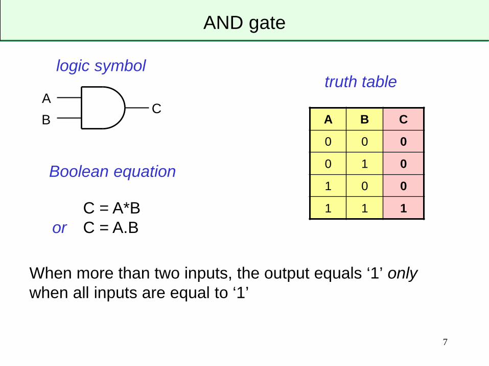
AND gate
When more than two inputs, the output equals ‘1’ onlywhen all inputs are equal to ‘1’
7
A B C
0 0 0
0 1 0
1 0 0
1 1 1
AB
C
logic symbol
Boolean equation
C = A*Bor C = A.B
truth table

OR gate
When more than two inputs, the output equals ‘1’ when any input is equal to ‘1’
8
A B C
0 0 0
0 1 1
1 0 1
1 1 1
AB
C
logic symbol
Boolean equation
C = A+B
truth table

Inverter or NOT gate
9
A Z
0 1
1 0
A Z
logic symbol
Boolean equation
truth table
Z = Aor Z = A'

NAND gate
When more than two inputs, the output equals ‘0’ only when all inputs are equal to ‘1’
10
A B C
0 0 1
0 1 1
1 0 1
1 1 0
AB
C
logic symbol
Boolean equation
C = A*B
or C = A.B
truth table
equivalent to:
AB
C

NOR gate
When more than two inputs, the output equals ‘0’ when any input is equal to ‘1’
11
A B C
0 0 1
0 1 0
1 0 0
1 1 0
A
BC
logic symbol
Boolean equation truth table
equivalent to:
AB
C
C = A+B

D = A⊕B
XOR and XNOR gate
When more than two inputs, the output of XOR equals ‘1’ only when an odd number of inputs are equal to ‘1’
12
A B C D
0 0 0 1
0 1 1 0
1 0 1 0
1 1 0 1
AB
C
XOR symbol
C = A⊕B
XOR/XNOR truth table
XNOR symbol
AB
D

Creating More Complex Logic Functions
13
ABC
D
EF
Z
Z=[(A.B.C) + D] + [D.(E+F)]

Some Useful Formulae
14
A + ‘0’ =
A + ‘1’ =
A + A =
A + A =
A • ‘0’ =
A •‘1’ =
A • A =
A • A =
A ⊕ ‘0’ =
A ⊕ ‘1’ =
A ⊕ A =
A ⊕ A =
A ⊕ B = (A • B) + (A • B)
A ⊕ B = (A • B) + (A • B)
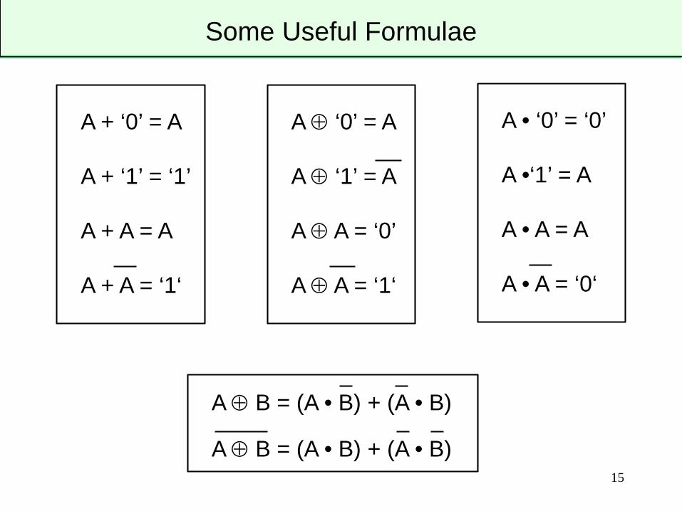
Some Useful Formulae
15
A + ‘0’ = A
A + ‘1’ = ‘1’
A + A = A
A + A = ‘1‘
A • ‘0’ = ‘0’
A •‘1’ = A
A • A = A
A • A = ‘0‘
A ⊕ ‘0’ = A
A ⊕ ‘1’ = A
A ⊕ A = ‘0’
A ⊕ A = ‘1‘
A ⊕ B = (A • B) + (A • B)
A ⊕ B = (A • B) + (A • B)

DeMorgan’s Theorem
16
A • B = A + B
A + B = A • B
1. Change AND to OR (OR to AND)
2. Invert all inputs
3. Invert output

17
• Y = A.B + C.D
Example: AOI22
ABCD
Y
AB
CD
Y
AB
CD
Y

18
• Z = S.A + S.B
Multiplexer
A
B
SZ
S A B Z
0 0 0 0
0 0 1 0
0 1 0 1
0 1 1 1
1 0 0 0
1 0 1 1
1 1 0 0
1 1 1 1
S A B Z
0 0 - 0
0 1 - 1
1 - 0 0
1 - 1 1
S Z
0 A
1 B
A
B
0
1
S
Z
19
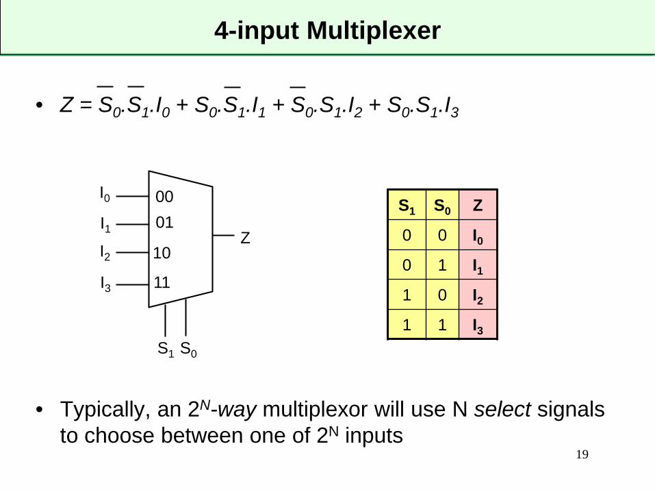
4-input Multiplexer
S1 S0 Z
0 0 I00 1 I11 0 I21 1 I3
• Z = S0.S1.I0 + S0.S1.I1 + S0.S1.I2 + S0.S1.I3
• Typically, an 2N-way multiplexor will use N select signals to choose between one of 2N inputs
I0 00
S1
Z01
10
11
S0
I1I2I3

20
Combinational vs. Sequential Logic
• A combinational circuit (logic) is one in which the output depends only on the current value of the inputs– All of the logic gates we have described so far (AND, NOR,
XOR, multiplexer etc.) are combinational– If you know the inputs you know the outputs
• A sequential circuit (logic) is one in which the output depends on the current value and previous values of the inputs– Output depends on the sequence of applied inputs – Sequential circuits include some form of memory of previous
inputs that modify output values– We often call these remembered values the state of the circuit or
system.– All sequential circuits include some form of feedback loop to feed
the remembered state back into the inputs of the circuit.

21
Memory – the cross coupled inverter
• Almost all form of digital memory are built around the idea of having two inverters (NOT gates) connected in a feedback loop.
• Positive feedback drives circuit into one of two stable states
• Either: (Y=1, Z=0) OR (Y=0, Z=1)– Circuit will hold state indefinitely
• How do we change the state?
Z
Y
RS Latch
2222
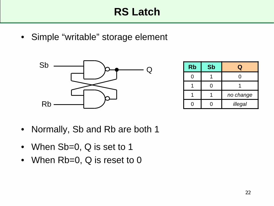
• Simple “writable” storage element
• Normally, Sb and Rb are both 1
• When Sb=0, Q is set to 1• When Rb=0, Q is reset to 0
Sb
Rb
Q Rb Sb Q0 1 0
1 0 1
1 1 no change
0 0 illegal
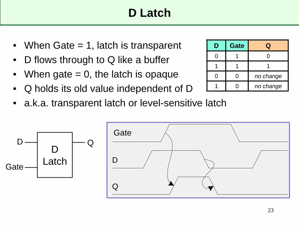
D Latch
23
• When Gate = 1, latch is transparent• D flows through to Q like a buffer• When gate = 0, the latch is opaque• Q holds its old value independent of D• a.k.a. transparent latch or level-sensitive latch
DLatch
D
Gate
Q
D Gate Q0 1 0
1 1 1
0 0 no change
1 0 no change
D
CLK
Q
Gate

D Flip-flop
24
• When CLK rises, D is copied to Q• At all other times, Q holds its value• a.k.a. edge-triggered flip-flop, master-slave flip-flop
clk D Q
0 X no change
1 X no change
↑ 1 1
↑ 0 0
Dflip-flop
D Q
clk
D
CLK
Q

25
Number Systems
Decimal (base10 )
𝐴𝐴 = �𝑖𝑖=0
𝑛𝑛−1
𝑎𝑎𝑖𝑖 . 10𝑖𝑖
1 0 0 1 1 1 0 127 26 25 24 23 22 21 20
=128+ 0+ 0 +16 +8 + 4 + 0 + 1 =15710
𝐴𝐴 = �𝑖𝑖=0
𝑛𝑛−1
𝑎𝑎𝑖𝑖 . 2𝑖𝑖
Binary (base2 )
1 5 7102 101 100
= (1x100)+(5x10)+(7x1)

26
Powers of 2
• 20 = 1• 21 = 2• 22 = 4• 23 = 8• 24 = 16• 25 = 32• 26 = 64• 27 = 128• 28 = 256
• 29 = 512• 210 = 1024• 211 = 2048• 212 = 4096• 213 = 8192• 214 = 16384• 215 = 32768• 216 = 65536• handy to memorize up to 210

27
Range of Binary Numbers
• N-digit decimal number – How many values? – Range? – Example: 3-digit decimal number:
• N-bit binary number– How many values?– Range: – Example: 3-bit binary number:
28
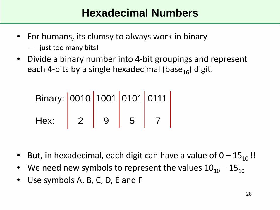
Hexadecimal Numbers
• For humans, its clumsy to always work in binary– just too many bits!
• Divide a binary number into 4-bit groupings and represent each 4-bits by a single hexadecimal (base16) digit.
• But, in hexadecimal, each digit can have a value of 0 – 1510 !!• We need new symbols to represent the values 1010 – 1510
• Use symbols A, B, C, D, E and F
Binary: 0010 1001 0101 0111
Hex: 2 9 5 7

Hexadecimal Numbers
• For example:
4AF16 =
0100 1010 11112
= (4 x 256) + (10 X 16)+ (15 x 1)
= 119910
29

30
Bits, Bytes and Nibbles…
• Bits:(8-bit binary)
• Bytes & Nibbles:(8-bit binary)
• Bytes:(32-bit hex)
1 0 0 1 0 1 1 0most
significantbit (MSB)
leastsignificantbit (LSB)
1 0 0 1 0 1 1 0byte (8 bits)
nibble(4 bits)
3 A C F 2 4 D 7
MSbyte LSbyte

31
Addition
• Decimal:
• Binary:
• Hex:
3 7 3 4+ 5 1 6 8
1 0 1 1+ 0 0 1 1
1 A 3 7+ 0 9 F 6

32
Overflow
• Note that if we add two n-bit numbers, we will (in general) getan (n+1) bit result:
1 0 1 0+ 0 1 1 1
1 0 0 0 1
1 1 1 carries
overflow

How do we deal with negative numbers?
Two common approaches:
• Sign-magnitude representation
• Two’s complement representation
Signed Binary Representation

• One sign bit plus n-1 magnitude bits• MSBit is the sign bit:
– MSB=0 means positive number– MSB=1 means negative number
• for example, for n=8:
• n-bit sign-magnitude number can take on values –(2n-1-1) to (2n-1-1)
34
Sign-Magnitude Representation
𝐴𝐴 = −1 𝑎𝑎𝑛𝑛−1 × �𝑖𝑖=0
𝑛𝑛−2
𝑎𝑎𝑖𝑖 . 2𝑖𝑖
0 0 0 1 0 1 1 1= +1 x (0 + 0 +16 +0 + 4 + 2 + 1) = 23
1 0 0 1 0 1 1 1= –1 x (0 + 0 +16 +0 + 4 + 2 + 1) = – 23
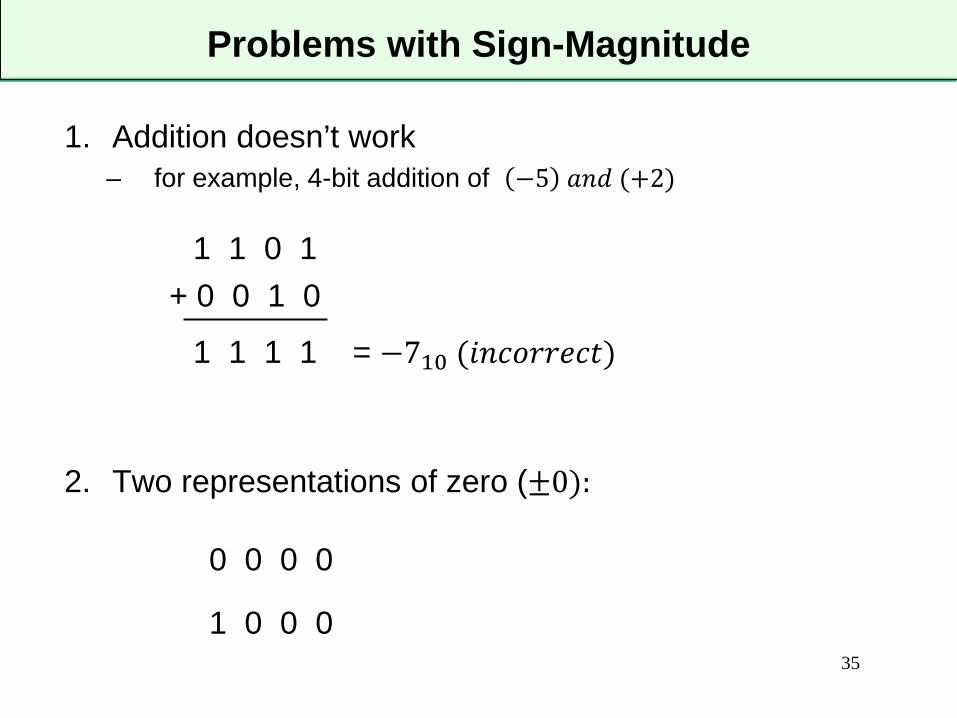
1. Addition doesn’t work– for example, 4-bit addition of −5 𝑎𝑎𝑎𝑎𝑎𝑎 (+2)
2. Two representations of zero (±0):
35
Problems with Sign-Magnitude
1 1 0 1+ 0 0 1 0
1 1 1 1 = −710 (𝑖𝑖𝑎𝑎𝑖𝑖𝑖𝑖𝑖𝑖𝑖𝑖𝑖𝑖𝑖𝑖𝑖𝑖)
0 0 0 0
1 0 0 0

• MSBit has value (−2𝑛𝑛−1) :
• for example, n=8:
• n-bit two’s complement number can take on values (-2n-1) to (2n-1-1) 36
Two’s Complement Representation
1 1 1 0 1 0 0 1
27 26 25 24 23 22 21 20
= -128 +64+32 +0 +8 + 0 + 0 + 1 = – 23
𝐴𝐴 = − 𝑎𝑎𝑛𝑛−1. 2𝑛𝑛−1 + �𝑖𝑖=0
𝑛𝑛−2
𝑎𝑎𝑖𝑖 . 2𝑖𝑖
0 0 0 1 0 1 1 1= 0 + 0 + 0 +16 +0 + 4 + 2 + 1 = 23
37
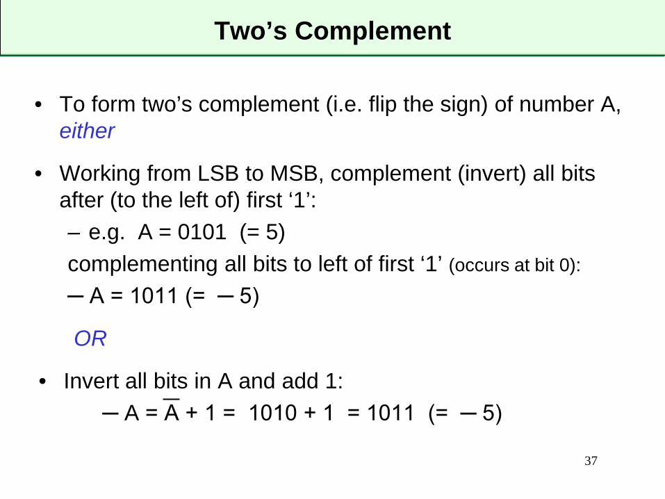
Two’s Complement
• To form two’s complement (i.e. flip the sign) of number A, either
• Working from LSB to MSB, complement (invert) all bits after (to the left of) first ‘1’:– e.g. A = 0101 (= 5)complementing all bits to left of first ‘1’ (occurs at bit 0):
─ A = 1011 (= ─ 5)
OR
• Invert all bits in A and add 1:─ A = A + 1 = 1010 + 1 = 1011 (= ─ 5)

1. MSB still indicates sign
2. Addition does work
3. Only one representation of zero:
38
Convenience of Two’s Complement
0 0 0 0
1 0 1 1 – 510
+ 0 0 1 0 + 210
1 1 0 1 −310 (𝑖𝑖𝑖𝑖𝑖𝑖𝑖𝑖𝑖𝑖𝑖𝑖𝑖𝑖!)
1 0 1 1 – 510
+ 0 1 1 1 + 710
1 0 0 1 0 +210 (𝑖𝑖𝑖𝑖𝑖𝑖𝑖𝑖𝑖𝑖𝑖𝑖𝑖𝑖!)
note: throw away the “overflow” bit
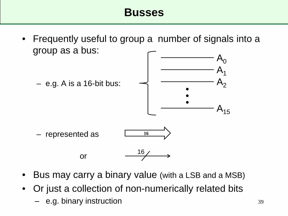
Busses
• Frequently useful to group a number of signals into a group as a bus:
– e.g. A is a 16-bit bus:
– represented as
or
• Bus may carry a binary value (with a LSB and a MSB)
• Or just a collection of non-numerically related bits– e.g. binary instruction 39
A0A1A2
A15
•••
16
16

Registers
• When we want to “remember” an N-bit value…– may be numerical value, instruction, code, address etc.
• We often group N D-flip-flops together to capture and store the value on the rising edge of a common clock
• We call this an N-bit register– e.g. 16-bit register
40
16
16-bit register
D Q
clk
A(0-15) 16 Z (0-15)


