1 LECTURE 26 Losses in Magnetic Devices Achieving acceptable loss levels in magnetic devices is the primary goal. A. Overview of Magnetic Device Losses B. Faraday’s and Lenz’s Law 1.B max in Cores from Faradays Law 2.Lenz Law and Its Implications for Induced Current Losses a. Skin Effects in Copper Wires b. Eddy Current Effects in Various Core Materials C. Magnetic Media B-H Curves and Losses 1. Basics of B-H Curves The Saturation Catastrophe 2. Losses in Magnetic Media a. Hysteresis Loss~ f(B AC ) m * Core Volume b. Eddy Current Loss~ f 2 (B ac ) n *Core Volume c. High f Ferrite Loss~ f 3 * Core Volume d.Summary of Losses versus B and f FOR HWS# 4 and 5 do the following: HW#4 Erickson Chapter 12 problems 6 and 8 and in class questions as well as lecture questions Hw# 5 Erickson Chapter 13 problem 3 and in class questions as well as lecture questions
Transcript
1
LECTURE 26Losses in Magnetic Devices
Achieving acceptable loss levels inmagnetic devices is the primary goal.A. Overview of Magnetic Device LossesB. Faraday’s and Lenz’s Law
1.Bmax in Cores from Faradays Law 2.Lenz Law and Its Implications for
Induced Current Lossesa. Skin Effects in Copper Wiresb. Eddy Current Effects in Various Core
MaterialsC. Magnetic Media B-H Curves and Losses
1. Basics of B-H CurvesThe Saturation Catastrophe
2. Losses in Magnetic Mediaa. Hysteresis Loss~ f(BAC)m * CoreVolumeb. Eddy Current Loss~ f2(Bac)n*CoreVolumec. High f Ferrite Loss~ f3 * Core Volumed.Summary of Losses versus B and f
FOR HWS# 4 and 5 do the following:HW#4 Erickson Chapter 12 problems 6 and 8 and in classquestions as well as lecture questionsHw# 5 Erickson Chapter 13 problem 3 and in class questions aswell as lecture questions
2
LECTURE 26Losses in Magnetic Devices
A. Overview of Magnetic Device Losses1. General Situation
Magnetic devices are composed of copper wires and magneticcore material. Losses in magnetic devices occur both in thecopper windings and in the magnetic core materials. One or theother loss mechanism can dominate depending on the particularsof the magnetic device operating conditions. Properly designedmagnetic devices should add up to no more than 1-5 % of thetotal losses in a switch mode electronics circuit. Solid statedevice losses will contribute a similar amount. Overall energyconversion efficiency should be 90 to 98 %.
2. Copper Wire Lossesa. Skin Effects on an Isolated Single Wire
The wire losses are I2R losses and the DC I2R levels are abaseline for comparison to losses at any other operatingfrequency. The ISOLATED SINGLE wire resistance increasesabove DC levels by factors of 2-10 through skin effects for highfrequency currents. The resistance of the wire is a function of thefrequency of the applied current,f, in the wire and chosen the wirediameter,D. The larger the wire diameter the bigger the skineffect. Roughly, RAC(wire) ~RDC(wire) f1/2 DFor now we intuitively plot the current density in a wire versus wireradius for the case of DC currents through some high frequencycurrent to visually see the trends prior to detailed mathematicalanalysis.
ar
J(DC) For dc conditions J isuniform over the wirediameter as we expect.
3
ar
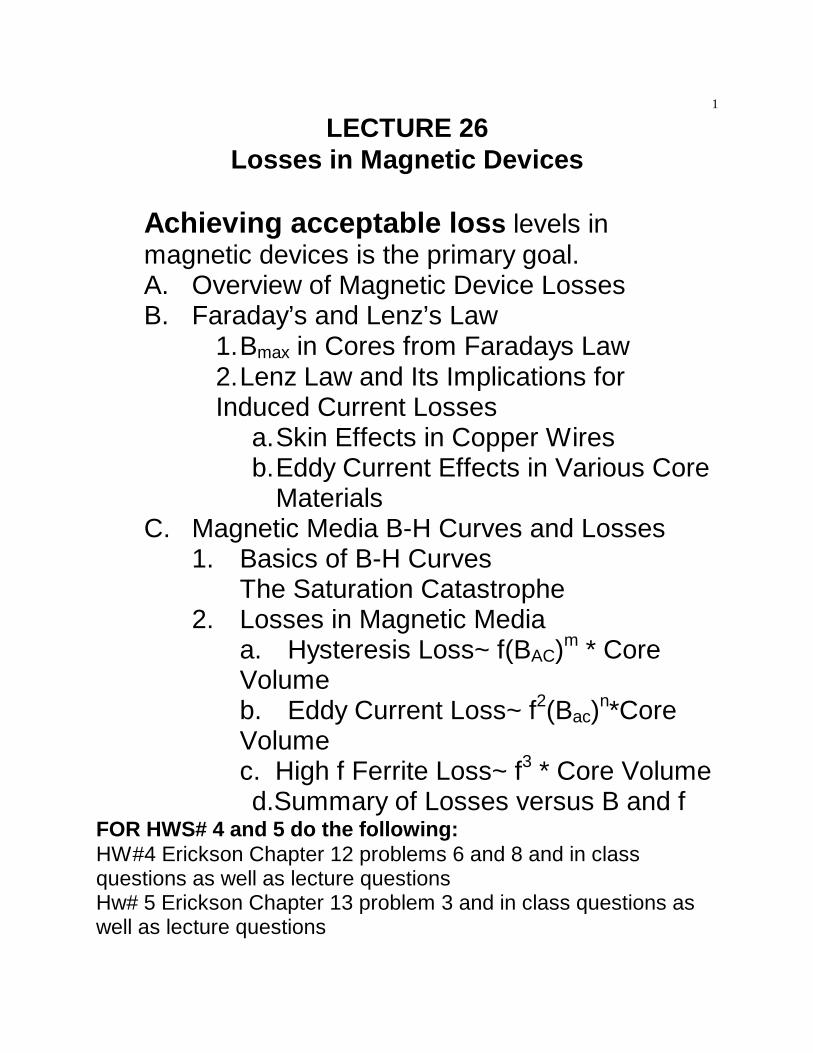
J(60 Hz) Even at mains ac J (60 Hz) has a small dip in J nearr = 0 of 1-3%. Why? This iswell known to increase ACtransmission line losses.
ar
J(MHz) For MHZ currents J flowsonly at or near the surfaceof the wire. No flow ofcurrent at r = 0. This makeswires look 2-100 times smaller.
We will see later in more detail how eddy currents in the copperwires induced by the time varying H field encircling the wire willalter J profiles as shown above to minimize total energy at theexpense of increasing I2 R losses.
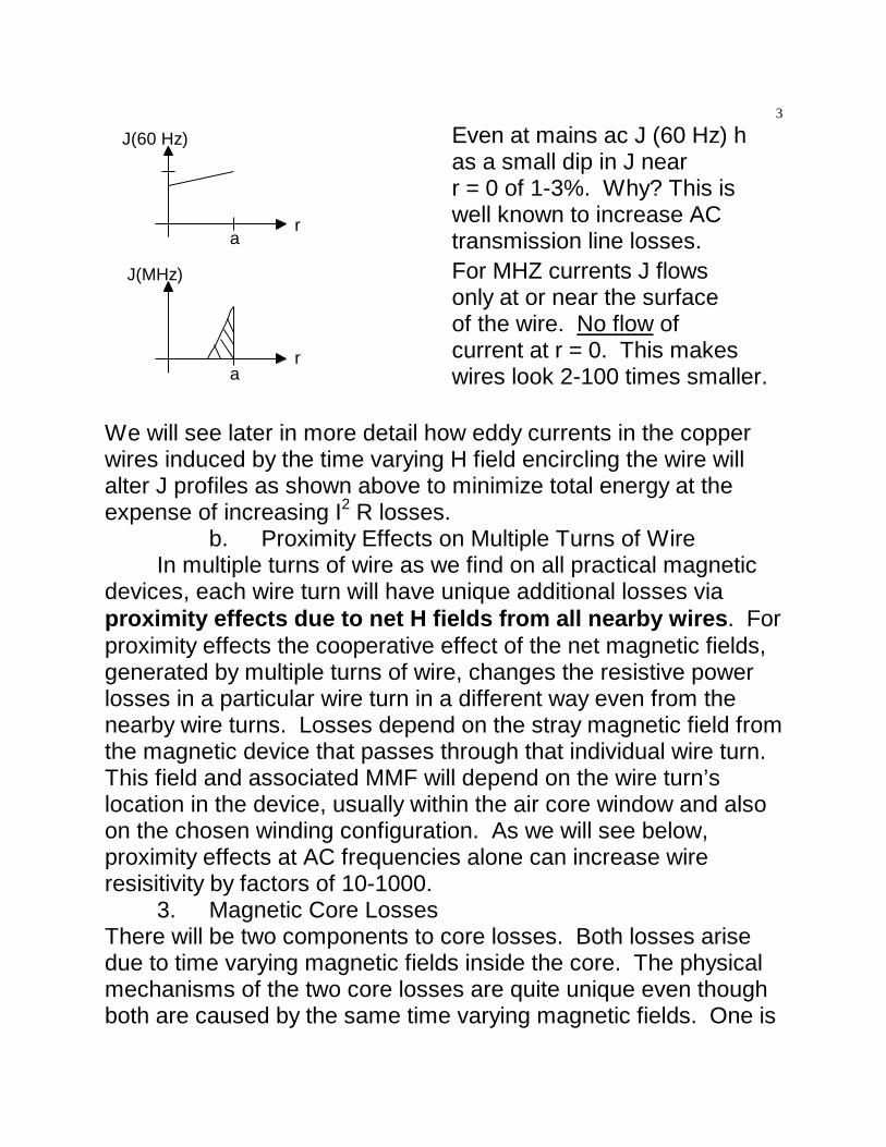
b. Proximity Effects on Multiple Turns of WireIn multiple turns of wire as we find on all practical magnetic
devices, each wire turn will have unique additional losses viaproximity effects due to net H fields from all nearby wires. Forproximity effects the cooperative effect of the net magnetic fields,generated by multiple turns of wire, changes the resistive powerlosses in a particular wire turn in a different way even from thenearby wire turns. Losses depend on the stray magnetic field fromthe magnetic device that passes through that individual wire turn. This field and associated MMF will depend on the wire turn’slocation in the device, usually within the air core window and alsoon the chosen winding configuration. As we will see below,proximity effects at AC frequencies alone can increase wireresisitivity by factors of 10-1000.
3. Magnetic Core LossesThere will be two components to core losses. Both losses arisedue to time varying magnetic fields inside the core. The physicalmechanisms of the two core losses are quite unique even thoughboth are caused by the same time varying magnetic fields. One is
4
due to hysteresis loss in the B-H curve and it varies linearly withthe frequency of the magnetic field variation. The second loss isdue to eddy currents induced in the core material and it varies asthe square of the frequency and inversely as the electricalresisitivity of the core material.
All of the loss processes for magnetic devices are covered indetail in this lecture except proximity effects on resistivity changesfor stacked turns of wire which are given in detail in lecture 28.B. Faraday’s and Lenz’s Law
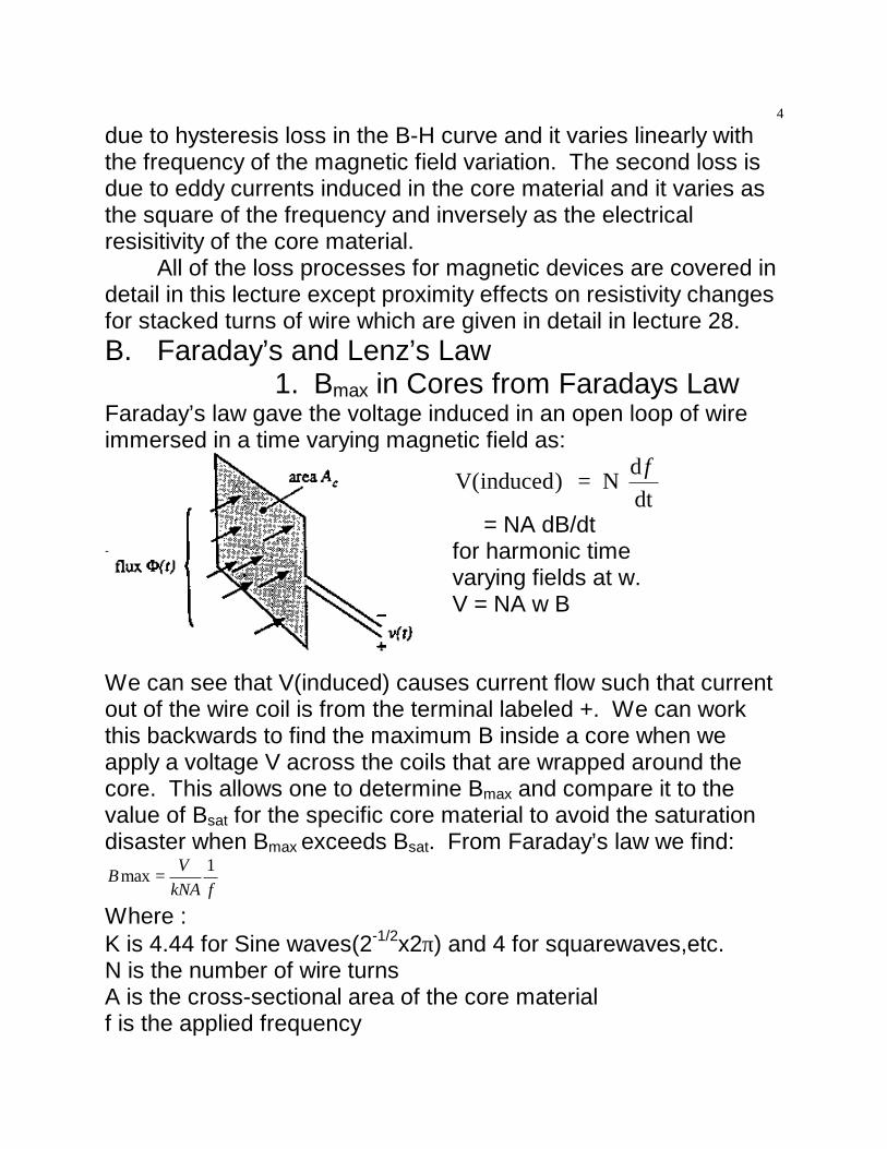
1. Bmax in Cores from Faradays LawFaraday’s law gave the voltage induced in an open loop of wireimmersed in a time varying magnetic field as:
V( ) = N ddt
inducedφ
= NA dB/dtfor harmonic timevarying fields at w.V = NA w B
We can see that V(induced) causes current flow such that currentout of the wire coil is from the terminal labeled +. We can workthis backwards to find the maximum B inside a core when weapply a voltage V across the coils that are wrapped around thecore. This allows one to determine Bmax and compare it to thevalue of Bsat for the specific core material to avoid the saturationdisaster when Bmax exceeds Bsat. From Faraday’s law we find:
Where :K is 4.44 for Sine waves(2-1/2x2π) and 4 for squarewaves,etc.N is the number of wire turnsA is the cross-sectional area of the core materialf is the applied frequency
fkNAVB 1max =
5
Bmax is also employed to find the hysteresis core losses whichdepend on peak B fields in the core rather than the RMS valve ofB. Design paths and compromises to lower Bmax values are clear.
2. Lenz’s Law and Its Implications toMagnetic Device Losses
a. Current LoopPlacing a CLOSED loop of wire in a time varying magnetic fieldwill induce a current in the wire to oppose the applied B field asshown below. This is the basis of electric motor design.Lenz’s Law: Loop of Shorted Wire in a φ(t) magnetic flux fieldThis corresponds to the situation in an electrical motor.
Induced i flow in the closed loopof wire at one moment of time issuch as to oppose the appliedflux at that same moment asseen by the right hand rule.
b. H Field Surrounding An Isolated Single WireNext consider a single isolated wire with a sinusoidal current at afrequency f flowing through it.A sinusoidal current i creates a +circular magnetic H field enclosing it. The field is moving in the θdirection both within the wire and outside the wire. Note also thatthe induced magnetic field can not distinguish the solid wire fromthe air surrounding it. Why? Is the permeability of copper differentfrom air??
6
x.I(f)
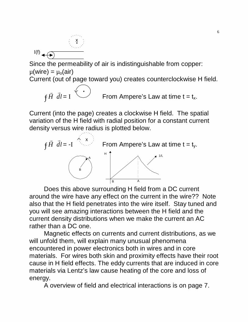
Since the permeability of air is indistinguishable from copper:µ(wire) = µo(air)Current (out of page toward you) creates counterclockwise H field.
r rH dl⋅∫ = I
.From Ampere’s Law at time t = tx.
Current (into the page) creates a clockwise H field. The spatialvariation of the H field with radial position for a constant currentdensity versus wire radius is plotted below.
r rH dl⋅∫ = -I
xFrom Ampere’s Law at time t = ty.
B
A
AB
H1/L
Does this above surrounding H field from a DC currentaround the wire have any effect on the current in the wire?? Notealso that the H field penetrates into the wire itself. Stay tuned andyou will see amazing interactions between the H field and thecurrent density distributions when we make the current an ACrather than a DC one.
Magnetic effects on currents and current distributions, as wewill unfold them, will explain many unusual phenomenaencountered in power electronics both in wires and in corematerials. For wires both skin and proximity effects have their rootcause in H field effects. The eddy currents that are induced in corematerials via Lentz’s law cause heating of the core and loss ofenergy.
A overview of field and electrical interactions is on page 7.
7
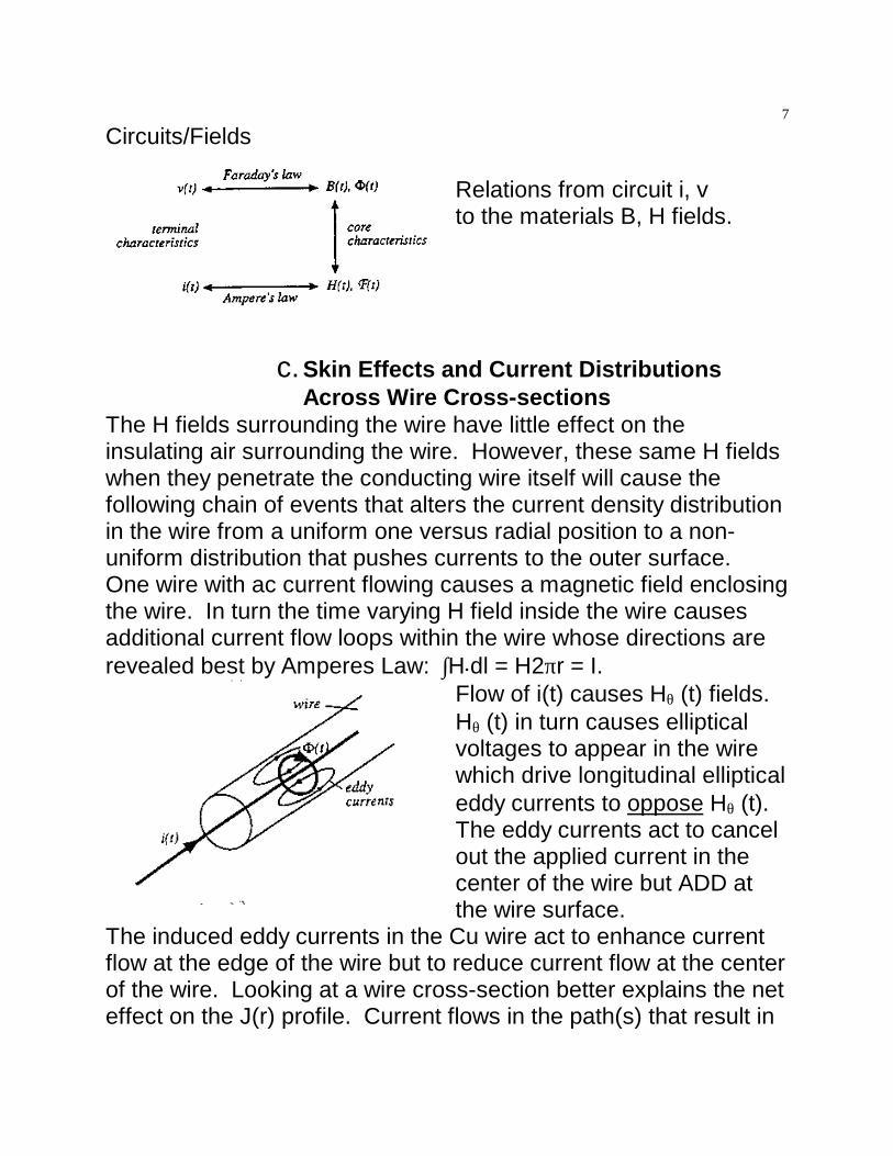
Circuits/Fields
Relations from circuit i, vto the materials B, H fields.
c. Skin Effects and Current DistributionsAcross Wire Cross-sections
The H fields surrounding the wire have little effect on theinsulating air surrounding the wire. However, these same H fieldswhen they penetrate the conducting wire itself will cause thefollowing chain of events that alters the current density distributionin the wire from a uniform one versus radial position to a non-uniform distribution that pushes currents to the outer surface.One wire with ac current flowing causes a magnetic field enclosingthe wire. In turn the time varying H field inside the wire causesadditional current flow loops within the wire whose directions arerevealed best by Amperes Law: ∫H•dl = H2πr = I.
Flow of i(t) causes Hθ (t) fields.Hθ (t) in turn causes ellipticalvoltages to appear in the wirewhich drive longitudinal ellipticaleddy currents to oppose Hθ (t). The eddy currents act to cancelout the applied current in thecenter of the wire but ADD atthe wire surface.
The induced eddy currents in the Cu wire act to enhance currentflow at the edge of the wire but to reduce current flow at the centerof the wire. Looking at a wire cross-section better explains the neteffect on the J(r) profile. Current flows in the path(s) that result in
8
the lowest expenditure of energy. At low frequency, this is simplyaccomplished by minimizing I2R losses only. At high frequencyhowever, current flow also occurs in path(s) that involve inductiveenergy. Now energy transfer to and from the magnetic fieldgenerated by the AC current flow, must also be minimized.Conservation of both resistive and inductive components causeshigh frequency current to flow nearer the surface of a largediameter wire conductor, even though this may result in muchhigher I2R losses. If there are several available paths, HF currentwill take the path(s) that minimize inductive energy flow.
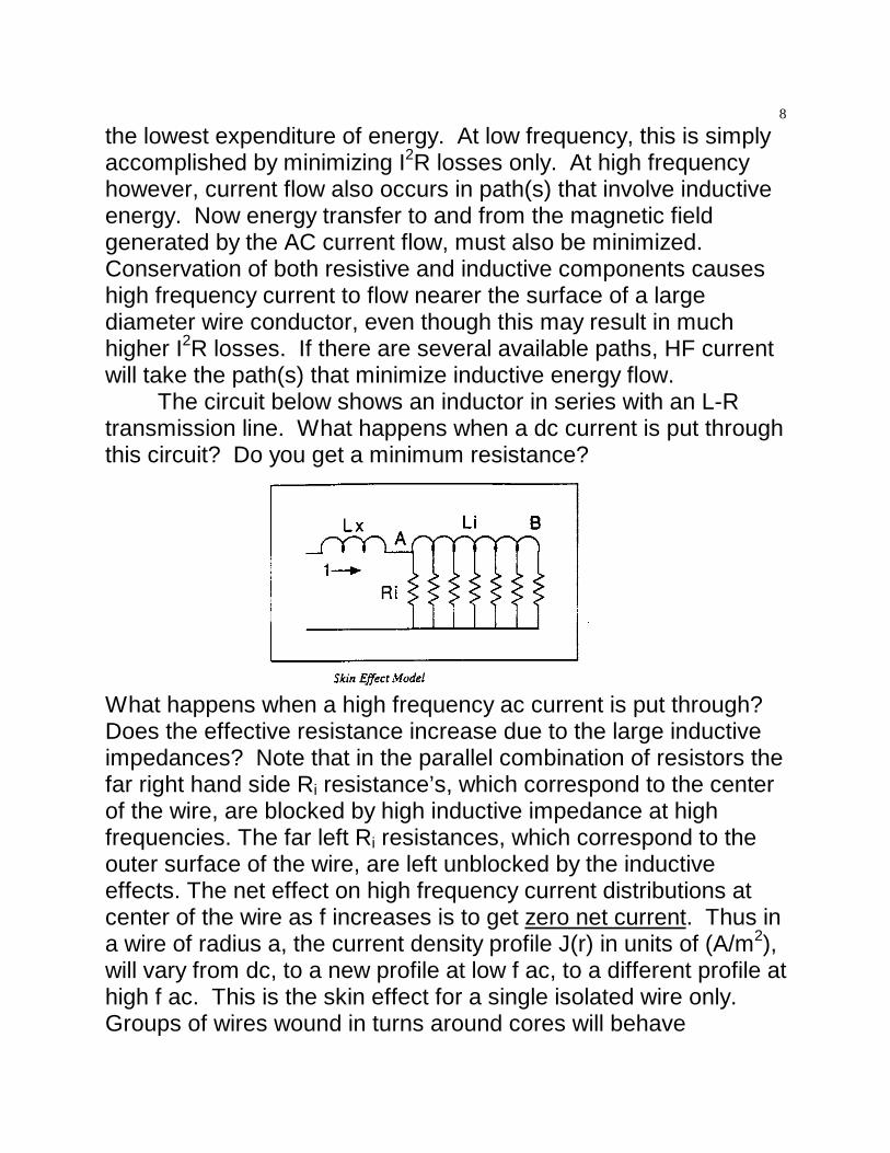
The circuit below shows an inductor in series with an L-Rtransmission line. What happens when a dc current is put throughthis circuit? Do you get a minimum resistance?
What happens when a high frequency ac current is put through? Does the effective resistance increase due to the large inductiveimpedances? Note that in the parallel combination of resistors thefar right hand side Ri resistance’s, which correspond to the centerof the wire, are blocked by high inductive impedance at highfrequencies. The far left Ri resistances, which correspond to theouter surface of the wire, are left unblocked by the inductiveeffects. The net effect on high frequency current distributions atcenter of the wire as f increases is to get zero net current. Thus ina wire of radius a, the current density profile J(r) in units of (A/m2),will vary from dc, to a new profile at low f ac, to a different profile athigh f ac. This is the skin effect for a single isolated wire only. Groups of wires wound in turns around cores will behave
9
differently as the H fields each wire sees will also vary.In summary, at dc or low frequency ac, energy transfer back
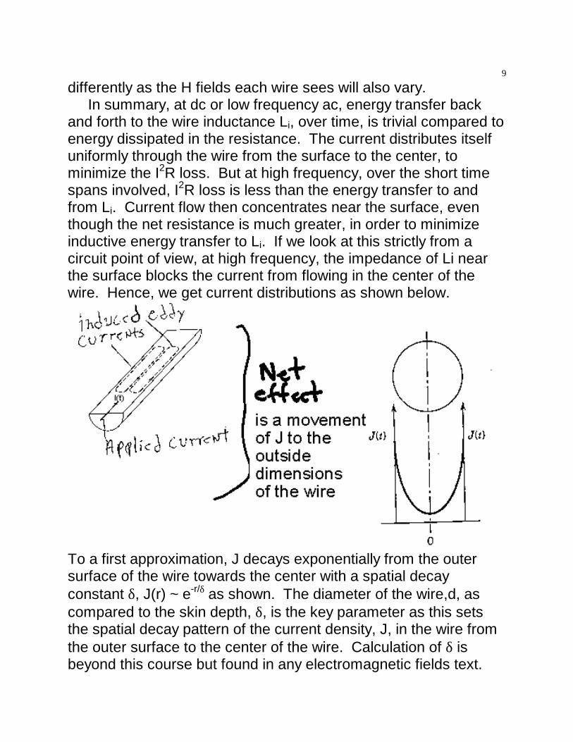
and forth to the wire inductance Li, over time, is trivial compared toenergy dissipated in the resistance. The current distributes itselfuniformly through the wire from the surface to the center, tominimize the I2R loss. But at high frequency, over the short timespans involved, I2R loss is less than the energy transfer to andfrom Li. Current flow then concentrates near the surface, eventhough the net resistance is much greater, in order to minimizeinductive energy transfer to Li. If we look at this strictly from acircuit point of view, at high frequency, the impedance of Li nearthe surface blocks the current from flowing in the center of thewire. Hence, we get current distributions as shown below.
To a first approximation, J decays exponentially from the outersurface of the wire towards the center with a spatial decayconstant δ, J(r) ~ e-r/δ as shown. The diameter of the wire,d, ascompared to the skin depth, δ, is the key parameter as this setsthe spatial decay pattern of the current density, J, in the wire fromthe outer surface to the center of the wire. Calculation of δ isbeyond this course but found in any electromagnetic fields text.
10
d
J(r) in wire
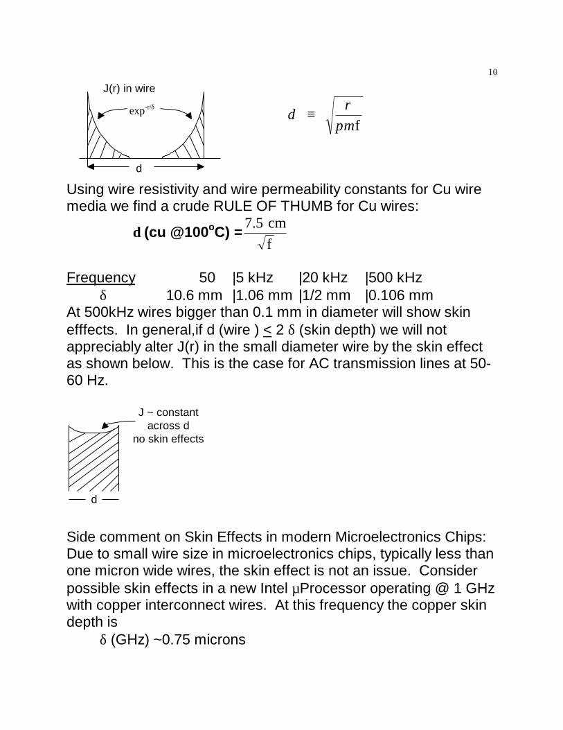
exp-r/δ δ ρπµ
f
≡
Using wire resistivity and wire permeability constants for Cu wiremedia we find a crude RULE OF THUMB for Cu wires:
δ (cu @100oC) =7.5 cm
f
Frequency 50 |5 kHz |20 kHz |500 kHzδ 10.6 mm |1.06 mm |1/2 mm |0.106 mm
At 500kHz wires bigger than 0.1 mm in diameter will show skinefffects. In general,if d (wire ) < 2 δ (skin depth) we will notappreciably alter J(r) in the small diameter wire by the skin effectas shown below. This is the case for AC transmission lines at 50-60 Hz.
d
J ~ constantacross d
no skin effects
Side comment on Skin Effects in modern Microelectronics Chips:Due to small wire size in microelectronics chips, typically less thanone micron wide wires, the skin effect is not an issue. Considerpossible skin effects in a new Intel µProcessor operating @ 1 GHzwith copper interconnect wires. At this frequency the copper skindepth is
δ (GHz) ~0.75 microns
11
Thus only for those chip wires bigger than 1.5 microns in diameterskin effects will play a role. Note this means there is no realbenefit going to thicker than 2µ copper metallization lines in theµProcessor wiring, as one might do especially for high AC currentsin wires. DC power busses will still benefit from wider dimensionwires. For copper interconnect, with wires around 1.5 microns wesee a break point. Below this value no skin effect occurs. Abovethis value of wire line width BIG skin effects occur.d < 1.5 µ wide signal bus d > 1.5 µwide wireRdc = Rac Rac>>RdcThis is counter intuitive for some people who expect less skineffect problems for thicker wires. It reality it is just the opposite.
As a consequence a bundle of thin wires is the way to makea effective large diameter wire in macroelectronics as practiced inpower electronics. This low AC loss type of wire is commerciallyavailable and is termed LITZ wire
Litzwire
345 strands of #35 wirein parallel strands are woven together.Each strand of Litz has adiameter ~ 200 microns
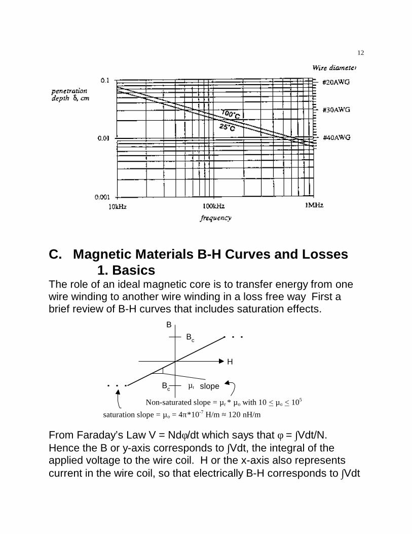
Copper wires come in specific wire sizes. For Cu wires the δ vs fplots can be compared to the standard AWG # and associatedwire diameter to better see when d > 2δ occurs and skin effectsare LARGE. With these wires we interconnect the convertercircuits containing solid state devices and magnetic devices. Aninformative plot of skin depth versus frequency benefits greatlywith horizontal notations of where the various wire sizes lie. Wedon’t want to specify a larger diameter wire to handle largecurrents only to find out a smaller diameter wire would do the jobjust as well. Page 12 plots of δ versus f with wire diameter as ahorizontal bar, when δ hits wire diameter, helps one keep thisrelative size relationship in mind.
12
C. Magnetic Materials B-H Curves and Losses1. Basics
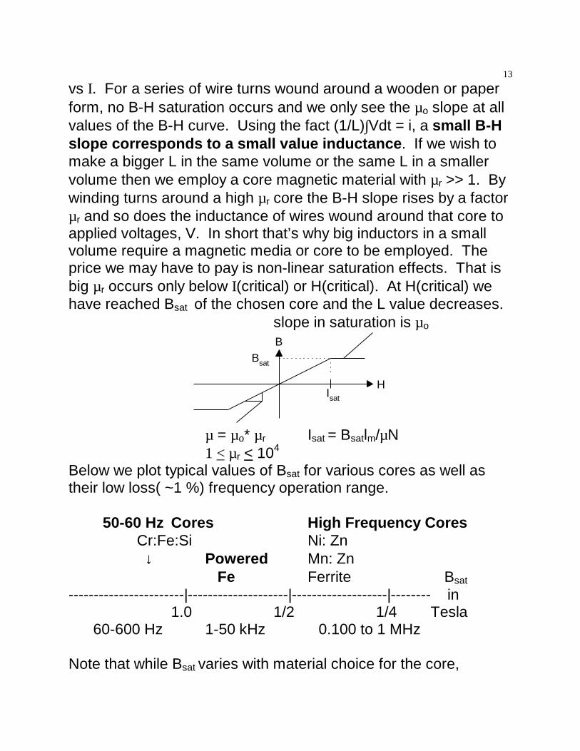
The role of an ideal magnetic core is to transfer energy from onewire winding to another wire winding in a loss free way First abrief review of B-H curves that includes saturation effects.
From Faraday’s Law V = Ndφ/dt which says that φ = ∫Vdt/N. Hence the B or y-axis corresponds to ∫Vdt, the integral of theapplied voltage to the wire coil. H or the x-axis also representscurrent in the wire coil, so that electrically B-H corresponds to ∫Vdt
13
vs I. For a series of wire turns wound around a wooden or paperform, no B-H saturation occurs and we only see the µo slope at allvalues of the B-H curve. Using the fact (1/L)∫Vdt = i, a small B-Hslope corresponds to a small value inductance. If we wish tomake a bigger L in the same volume or the same L in a smallervolume then we employ a core magnetic material with µr >> 1. Bywinding turns around a high µr core the B-H slope rises by a factorµr and so does the inductance of wires wound around that core toapplied voltages, V. In short that’s why big inductors in a smallvolume require a magnetic media or core to be employed. Theprice we may have to pay is non-linear saturation effects. That isbig µr occurs only below I(critical) or H(critical). At H(critical) wehave reached Bsat of the chosen core and the L value decreases.
slope in saturation is µo
B
H
Bsat
Isat
µ = µo* µr Isat = Bsatlm/µN1 < µr < 104
Below we plot typical values of Bsat for various cores as well astheir low loss( ~1 %) frequency operation range.
50-60 Hz Cores High Frequency Cores Cr:Fe:Si Ni: Zn ↓ Powered Mn: Zn
Fe Ferrite Bsat
-----------------------|--------------------|-------------------|-------- in1.0 1/2 1/4 Tesla
60-600 Hz 1-50 kHz 0.100 to 1 MHz
Note that while Bsat varies with material choice for the core,
14
unfortunately, Bsat for various cores only varies over ONE ORDEROF MAGNITUDE. The science of high permeability cores needsfurther work to catch up to the needs of technology.Common Materials choices and Manufacturers are listed below.
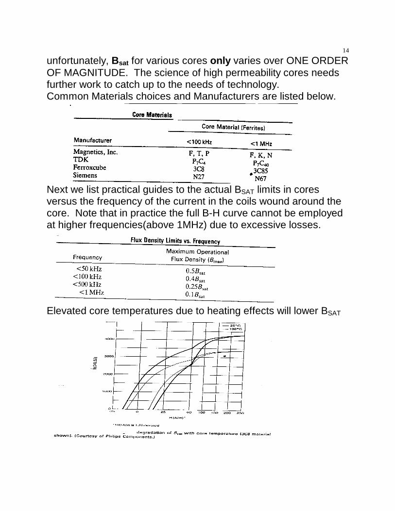
Next we list practical guides to the actual BSAT limits in coresversus the frequency of the current in the coils wound around thecore. Note that in practice the full B-H curve cannot be employedat higher frequencies(above 1MHz) due to excessive losses.
Elevated core temperatures due to heating effects will lower BSAT
15
. The last big breakthrough in magnetics came in the move fromiron to ferrites
Please note that the transition from Si:Fe cores to ferrites losesonly 4 * Bsat but gains 105 in the frequency range of operation ofthe core. Recall that ZL = wL, so if ZL counts more than just L, wegain a lot more inductive impedance by choosing Ferrite coresoperating at high frequency over traditional Fe-Si operating at 50-60 Hz for both transformers and inductors assuming equal corelosses at the very different frequencies.
Get rich and invent a core material with large values of Bsatand low losses at high frequencies-like at 13.56 MHzWe need a new breakthrough for achieving high Bsat materials foremploying high I inductors without saturation fears.FOR HW#5 COME UP WITH SOME WAYS to do so. A goodterm paper would involve:.New METGLASS material: 80% iron
20% glassBsat ≈ 3/4 Tesla
a. Inductor Considerations Inductor
ZL (ferrite)ZL (iron : Si)
≈ 105 difference in size required dueto operating frequency change
For fixed ZL we could have an inductor 105 smaller in size andweight by choosing the proper core material that operates at thesame total loss but at 105 higher frequency.
b. Transformer ConsiderationsTransformers on Different Cores
V = Ndφ/dt = NwφV (MHz)V (60Hz)
≈ 105 due to operating frequency
16
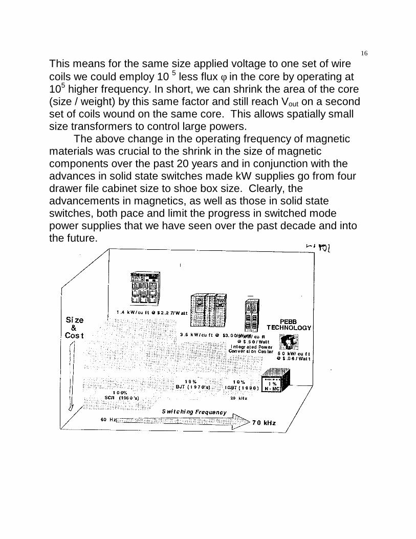
This means for the same size applied voltage to one set of wirecoils we could employ 10 5 less flux φ in the core by operating at105 higher frequency. In short, we can shrink the area of the core(size / weight) by this same factor and still reach Vout on a secondset of coils wound on the same core. This allows spatially smallsize transformers to control large powers.
The above change in the operating frequency of magneticmaterials was crucial to the shrink in the size of magneticcomponents over the past 20 years and in conjunction with theadvances in solid state switches made kW supplies go from fourdrawer file cabinet size to shoe box size. Clearly, theadvancements in magnetics, as well as those in solid stateswitches, both pace and limit the progress in switched modepower supplies that we have seen over the past decade and intothe future.
17
2. Losses in Magnetic Coresa. Overview
Core loss is the second most important core limitation in mostPWM converter applications after active switch losses. . Energylosses cause cores to heat up during operation. Losses arise fromboth hysteresis effects and eddy currents.
In metal alloy cores, eddy current loss dominates above afew hundred Hertz but this is not the case for ferrites until muchhigher frequency. For acceptable ferrite core losses, flux densityswing ∆B must be restricted to much less than Bsat, which preventsthe core from being utilized to its full capability. At lowfrequencies, ferrite core loss is almost entirely hysteresis loss. Fortoday’s power ferrites operating at high frequency, eddy currentloss overtakes hysteresis loss at 200-300kHz..
Core manufacturers usually provide curves showing coreloss as a function of flux swing and frequency, combininghysteresis and eddy current losses. Core loss is usuallyexpressed in mW/cm3, sometimes in kW/m3 (actually equal : 1mW/cm3 = 1KW/m3). Now lets discuss quantitatively two corelosses: hysteresis and eddy currents.a. Hysteresis Loss
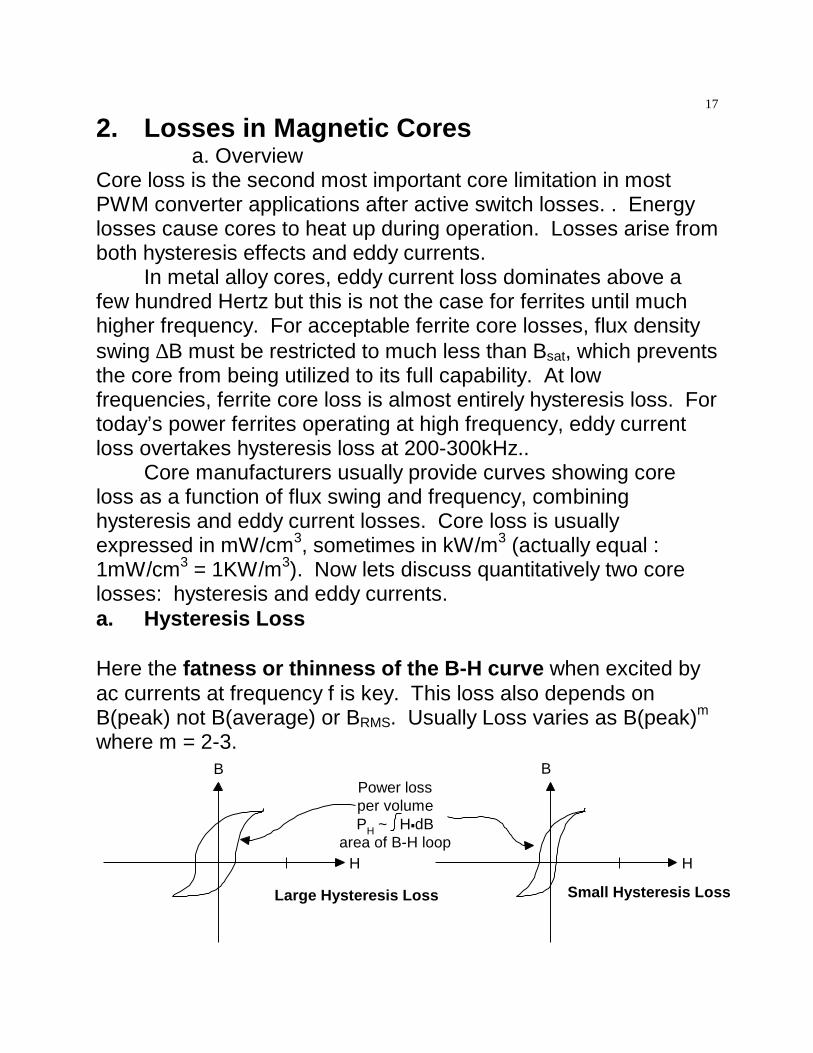
Here the fatness or thinness of the B-H curve when excited byac currents at frequency f is key. This loss also depends onB(peak) not B(average) or BRMS. Usually Loss varies as B(peak)m
where m = 2-3.B
H
Large Hysteresis Loss
B
H
Small Hysteresis Loss
Power lossper volumePH ~ H dB
area of B-H loop.
18
Notice also this loss occurs over each ac cycle so total loss isproportional to applied frequency f.
Total power Loss ≡ ∫ H•B * f * Volume of Core energy loss
per volume per cycle
Ploss(Hysteresis) ~
core material type
and
B (peak)ac
* f * core size
Bm(peak) is less if core area is bigger, yet the total loss decreasesas the core size gets smaller. So optimum geometry’s for coresthat minimize total loss do exist. These optimums will also have toinclude core cooling effects. Circuit topology also effects the B-Hcurve. For example how many quadrants of B-H are employeddepends on whether the wire current that is wrapped around acore is unipolar or bipolar driven by the converter switches. “L” ina forward converter, for example, is only in quadrant 1 of the B-Hbecause the diode allows only uni-directional current. Hence, weexpect higher B sat and losses may be bigger than for bipolarexcitation where BSAT is lower.
B
Hi(peak)
Forward converterB-H region
limits Bac(peak)
Clearly in a forward converter both the fsw and Vg choices also
19
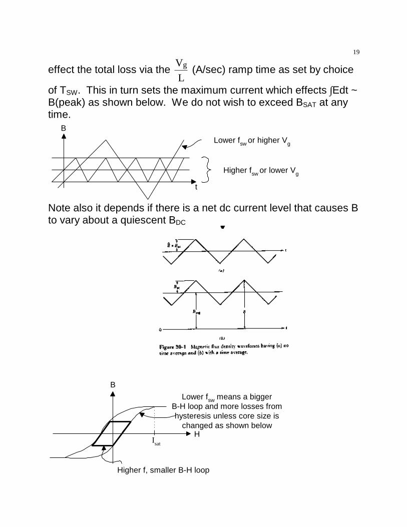
effect the total loss via the gVL
(A/sec) ramp time as set by choice
of TSW. This in turn sets the maximum current which effects ∫Edt ~B(peak) as shown below. We do not wish to exceed BSAT at anytime.
B
t
Higher fsw or lower Vg
Lower fsw or higher Vg
Note also it depends if there is a net dc current level that causes Bto vary about a quiescent BDC
B
H
Lower fsw means a biggerB-H loop and more losses fromhysteresis unless core size is
changed as shown below
Higher f, smaller B-H loop
Isat
20
satI satB mlN≡ µ Where N is the # of copper wire turns around the
core and lm is the perimeter length of the chosen core.Lower Vg or Higher f means Smaller Bac← → Smaller Core Sizerequired for same total loss.
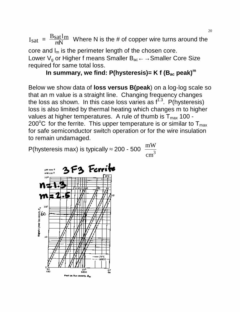
In summary, we find: P(hysteresis)= K f (Bac peak)m
Below we show data of loss versus B(peak) on a log-log scale sothat an m value is a straight line. Changing frequency changesthe loss as shown. In this case loss varies as f1.3. P(hysteresis)loss is also limited by thermal heating which changes m to highervalues at higher temperatures. A rule of thumb is Tmax 100 -200oC for the ferrite. This upper temperature is or similar to Tmaxfor safe semiconductor switch operation or for the wire insulationto remain undamaged.
P(hysteresis max) is typically ≈ 200 - 500 mWcm3
21
Consider changing the operating f from 100 to 400 kHz onthe wire current wound around 3F3 ferrite for use as an inductorcore. Start with @100 kHz and Bac = 100 mT the power lossdensity in the core is, P = 60 mW/cm3. By increasing operating f
to 400 KHz the power loss density is 10* greater, P = 600mW
cm3 ,
and not simply 4 times greater due to non-linear core heating.We repeat the warning that in Core Loss vs. Flux
Density curves, the horizontal axis labeled “Flux Density” usuallyrepresents peak flux density. In applications, peak-to-peak fluxswing, ∆B, is calculated from Faraday’s Law, where ∫Edt = appliedVolt-seconds, N = turns, and Ac = core cross-sectional area:
∆B = (1/NAc)∫V1dtThe total flux swing, ∆B, is sometimes twice the peak flux
swing referred to in the core loss curves as “Flux Density” if wechoose unipolar versus bipolar core excitation. Therefore, usecare to employ either ∆B/2 or ∆B to enter into the core loss curves.
v1
t
low fswhigh fsw
Aside:Later we will show that for transformers (but not forinductors)
V-A rating ← → f * Bac producttransformer
The fxBac product versus applied f peaks at a characteristicfrequency unique to each magnetic material. 3F4 Material isconsidered one of the best for high f operation as shown in the
22
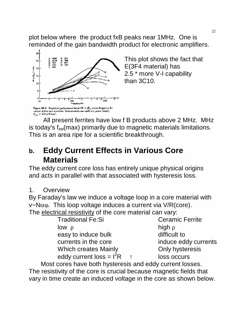
plot below where the product fxB peaks near 1MHz. One isreminded of the gain bandwidth product for electronic amplifiers.
This plot shows the fact thatE(3F4 material) has2.5 * more V-I capabilitythan 3C10.
All present ferrites have low f B products above 2 MHz. MHzis today’s fsw(max) primarily due to magnetic materials limitations. This is an area ripe for a scientific breakthrough.
b. Eddy Current Effects in Various CoreMaterials
The eddy current core loss has entirely unique physical originsand acts in parallel with that associated with hysteresis loss.
1. OverviewBy Faraday’s law we induce a voltage loop in a core material withv~Nωφ. This loop voltage induces a current via V/R(core).The electrical resistivity of the core material can vary:
Traditional Fe:Si Ceramic Ferritelow ρ high ρ easy to induce bulk difficult tocurrents in the core induce eddy currentsWhich creates Mainly Only hysteresiseddy current loss = I2R ↑ loss occurs
Most cores have both hysteresis and eddy current losses. The resistivity of the core is crucial because magnetic fields thatvary in time create an induced voltage in the core as shown below.
23
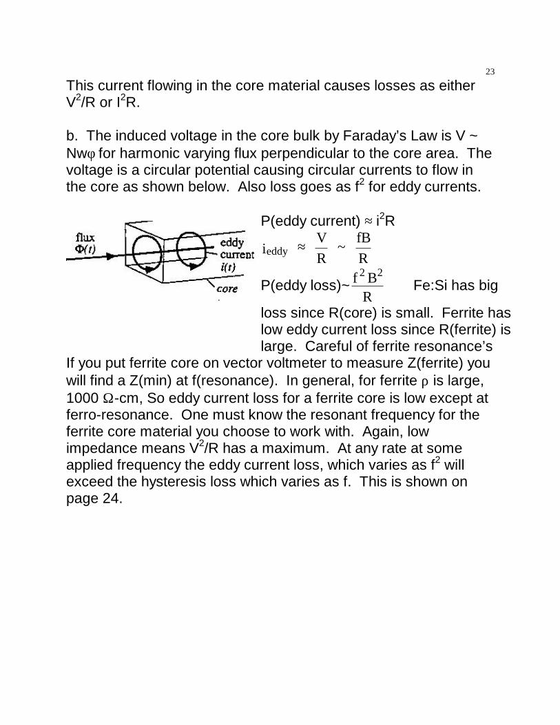
This current flowing in the core material causes losses as eitherV2/R or I2R.
b. The induced voltage in the core bulk by Faraday’s Law is V ~Nwφ for harmonic varying flux perpendicular to the core area. Thevoltage is a circular potential causing circular currents to flow inthe core as shown below. Also loss goes as f2 for eddy currents.
P(eddy current) ≈ i2R
eddyi VR
~ fBR
≈
P(eddy loss)~2 2f BR
⇒ Fe:Si has big
loss since R(core) is small. Ferrite haslow eddy current loss since R(ferrite) islarge. Careful of ferrite resonance’s
If you put ferrite core on vector voltmeter to measure Z(ferrite) youwill find a Z(min) at f(resonance). In general, for ferrite ρ is large,1000 Ω -cm, So eddy current loss for a ferrite core is low except atferro-resonance. One must know the resonant frequency for theferrite core material you choose to work with. Again, lowimpedance means V2/R has a maximum. At any rate at someapplied frequency the eddy current loss, which varies as f2 willexceed the hysteresis loss which varies as f. This is shown onpage 24.
24
Z
f
"L like"Behavior
"C like"Behavior
At the material Ferroresonance Z is reducedand eddy current losses
increase from thereexpected form Z(dc)
R
P(loss)
P(eddy current)
P(hysteresis)
ffco
low f high fhysteresis eddy currentloss loss dominates
fco, f(crossover) is typically 100 kHz.
At low f We canhysteresis dominates reduce eddy current by
laminating the core toblock eddy currentsunless you use high ρferrite cores. Atvery high f(MHz)Ploss(ferrites) ~ f3
High Frequency CoresNo high ρ ferrites exist with simultaneous high Bsat in the MHz
25
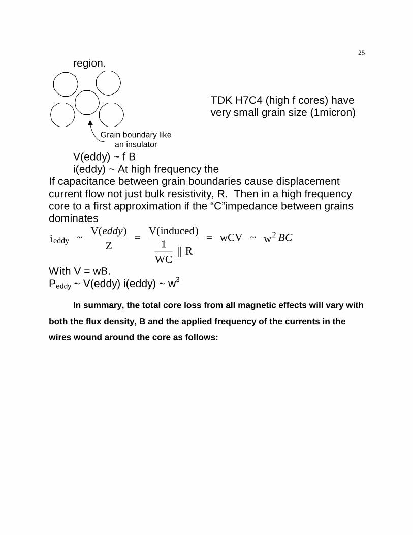
region.
Grain boundary likean insulator
TDK H7C4 (high f cores) havevery small grain size (1micron)
V(eddy) ~ f Bi(eddy) ~ At high frequency the
If capacitance between grain boundaries cause displacementcurrent flow not just bulk resistivity, R. Then in a high frequencycore to a first approximation if the “C”impedance between grainsdominates
eddy2i ~
V( )Z
= V( )
1WC
|| R = ~ w
eddyBC
inducedwCV
With V = wB.Peddy ~ V(eddy) i(eddy) ~ w3
In summary, the total core loss from all magnetic effects will vary with
both the flux density, B and the applied frequency of the currents in the
wires wound around the core as follows:
26
The small region in the power loss-B curve with a star,*,represents the suggested operation region to achieve thecondition that the core losses are well below the 1-5% of thetransmitted power through the core.
What is left for later lectures is what the lost energy does tothe temperature of the core. Later we will balance energy lossinput to the core with energy lost to the environment by variouscooling paths and end up with the equilibrium temperature of thecore under operation conditions. This temperature should neverexceed 100 degrees Centigrade to preserve both the core and thewire insulation.
FOR HWS# 4 and 5 do the following:HW#4 Erickson Chapter 12 problems 6 and 8 and in classquestions as well as lecture questions
27
Hw# 5 Erickson Chapter 13 problem 3 and in class questions aswell as lecture questions