55
Lecture 3: Controlling Errors CS 3035/GZ01: Networked Systems Kyle Jamieson Department of Computer Science University College London

Lecture 3: Controlling Errors
CS 3035/GZ01: Networked SystemsKyle Jamieson
Department of Computer ScienceUniversity College London

2
Recall (Lecture 1): Bit errors on links• Links in a network go through hostile environments– Both wired, and wireless:
– Consequently, errors will occur on links– Today: How can we control (i.e., detect and correct) these
errors?
• There is a limited capacity available on any link– Tradeoff between link utilization and amount of error control
Networked Systems 3035/GZ01
Scattering
Diffraction
Reflection

3
Today
1. Error control codes– How many errors can we handle?– Measuring a code’s overhead: Code rate
2. Practical error control codes3. The Internet checksum
Networked Systems 3035/GZ01

4
• The techniques we’ll discuss today are pervasive throughout the internetworking stack
• Based on theory, but broadly applicable in practice, in other areas:– Hard disk drives– Magnetic tape media– Optical media (CD, DVD, & c.)– Satellite, mobile communications– Deep space, submarine
communications
• In Networked Systems, we cover just the basic concepts
Where is error control coding used?
Networked Systems 3035/GZ01
Application
Transport
Network
Link
Physical
Internet protocol stack

5
Error control in the Internet stack• Transport layer (L4)
– Internet Checksum (IC) over TCP or UDP header and data
• Network layer (L3)– Internet Checksum (IC) over IP
header only
• Link layer (L2)– Cyclic Redundancy Check (CRC)
• Physical layer (PHY)– Forward Error Correction (FEC) or
Error Control Coding (ECC)Networked Systems 3035/GZ01
PHY payload
LL header LL payload LL CRC
IC IP payload
IC TCP payload
IP header
TCP header

6
Error control: the fundamental problem
• Sender transmits a message to receiver through the network
• Every string of bits is a possible legitimate message– Hence any errors (changes) to the bits the sender transmits
result in equally-legitimate messages
• Therefore, errors happen, but without error control, receiver wouldn’t know about them!
Networked Systems 3035/GZ01
Sender Receiver
Networkmessage

7
Error control coding• Key idea: Reduce the set of legitimate messages– Not every string of bits is an “allowed” message– Receipt of a disallowed string of bits means that the
message was garbled in transit over the network
• We call an allowable message of n bits a codeword– Not all n-bit messages are codewords!– The remaining n-bit strings are “space” between
codewords
• We will use these ideas to both detect and correct errors in transmitted messages
Networked Systems 3035/GZ01

8
Encoding and decoding
• Problem: Not every string of bits is “allowed” – But we want to be able to send any message!– How can we send a “disallowed” message?
• Answer: Sender-receiver protocol– The sender must encode its messages codewords➜– The receiver then decodes received bits messages➜
• We’ll look at simple codes today, but the relationship between messages and codewords isn’t always obvious!
Networked Systems 3035/GZ01

9
A simple error-detecting code (1/4)
• Let’s start simple: suppose messages are one bit long
• Let’s take each bit we want to send and repeat it once– This is called a two-repetition code
Networked Systems 3035/GZ01
00
11
01
10
Sender:
0
1
➜
➜

10
A simple error-detecting code (2/4)
• What happens at the receiver?– If the network makes no errors, the receiver removes the
repetition to correctly decode the received codeword
Networked Systems 3035/GZ01
00
11
Sender: Receiver:Network:
0
1
➜
➜
00 0➜
11 1➜
01
10

11
A simple error-detecting code (3/4)• If the network makes one bit error, receiver sees a non-codeword
message and detects an error– Can the receiver correct the error?– No! The other codeword could have been sent as well• The receiver has no way of telling which codeword was sent
in this case, so cannot correct the error
Networked Systems 3035/GZ01
00
11
Sender: Receiver:Network:
0
1
➜
➜
00 0➜
11 1➜
01
10
Error detected
Error detected
01
10

12
A simple error-detecting code (4/4)• Can the receiver detect the presence of two bit errors?
– No: It has no way of telling which codeword was sent!– What happened? The network flipped so many bits that the
message “jumped over” the space between codewords
• Let’s try to generalize this reasoning to any error-detecting code…
Networked Systems 3035/GZ01
00
11
Sender: Receiver:Network:
0
1
➜
➜
00 0➜
11 1➜
01
10Space between
codewords:

13
Hamming distance• How do we measure space between codewords?– Idea: Measure the number of bit flips to change one
codeword into another– Hamming distance between two messages m1, m2: The
number of bit flips needed to change m1 into m2
• Example: Two bit flips are needed to change codeword 00 to codeword 11, so they are Hamming distance of two apart
Networked Systems 3035/GZ01
00 01 11

14
How many bit errors can we detect?• Suppose the minimum Hamming distance between any pair
of codewords is dmin – Some pairs may be separated by different Hamming
distances than others
• Then, we can detect ≤ dmin− 1 bit flips– This many are guaranteed to land in the space between
codewords, as we just saw– Receiver will flag message as “Error detected”
Networked Systems 3035/GZ01
dmin = 3
2 bit errors

15
Decoding error detecting codes• Decoding is a two-step process:
1. The receiver maps received bits codewords– Decoding rule: Consider all codewords, choose the
one that exactly matches received bits, or “error detected” if none match
2. The receiver maps codewords source bits and “error detected”
Networked Systems 3035/GZ01
16
A simple error-correcting code
Networked Systems 3035/GZ01
000
010100011101110111
000001010100011101110111
➜0
1 ➜
0
1
Sender: Receiver:Network:
001
Fix error
➜
➜
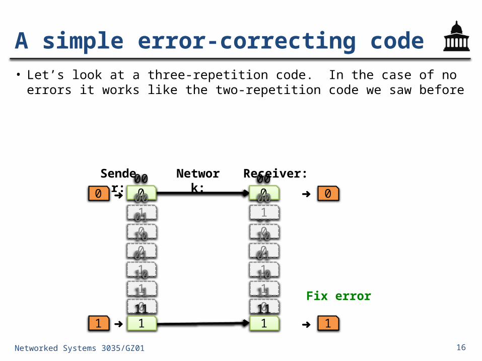
• Let’s look at a three-repetition code. In the case of no errors it works like the two-repetition code we saw before

17
A simple error-correcting code• The receiver can fix one bit error
– Chooses the closest codeword (in Hamming distance) to received bits– This amounts to drawing a decision boundary halfway between
codewords and choosing closest
Networked Systems 3035/GZ01
000
010100011101110111
000001010100011101110111
➜0
1 ➜
0
1
Sender: Receiver:Network:
001
Fix error
Fix error
➜
➜
Decision boundary

18
Decoding error correcting codes• Decoding is a two-step process:
1. The receiver maps received bits codewords– Decoding rule: Consider all codewords, select one
with the minimum Hamming distance to the received bits
2. The receiver maps codewords source bits
Networked Systems 3035/GZ01

19
How many bit errors can we correct?
• Suppose there is ≥ dmin Hamming distance between any codeword pair
• Then, we can correct ≤ bit flips– This many bit flips can’t move received bits closer to
another codeword, across the decision boundary:
Networked Systems 3035/GZ01
dmin = 5
2 bit errors
Decision boundary
Round down
20
Code rate• Suppose codewords are of length n, messages length k
• There is overhead involved in controlling errors: codewords are as long or longer than the messages they describe
• The code rate R = k/n measures this overhead
• So, we have a tradeoff:– High-rate codes (R approaching one) correct fewer
errors, but add less overhead– Low-rate codes (R close to zero) correct more errors,
but add more overheadNetworked Systems 3035/GZ01

21
Today
1. Error detecting and correcting codes2. Practical error control codes– Parity, and 2-D parity– Block codes: Hamming (7, 4) code– Polynomial codes: Cyclic redundancy check
3. The Internet checksum
Networked Systems 3035/GZ01

22
Parity bit• Fundamental building block for most other codes
• Given a message of k data bits D1, D2, …, Dk, append a parity bit P to make a codeword of length n = k + 1
– Pick the parity bit so that total number of 1’s is even
– The parity bit P is the exclusive-or of the data bits: • P = D1 D⊕ 2 D⊕⋯⊕ k
Networked Systems 3035/GZ01
011100 1
k data bits parity bit

23
Checking the parity bit• At the receiver: is there an even number of 1’s in the
received message?– If so, received message is a codeword– If not, isn’t a codeword, and error detected • But receiver doesn’t know where, so can’t correct
• Consider minimum distance between codewords dmin:– Change one data bit change parity bit, so dmin = 2– Therefore, a parity bit detects at most one bit error,
corrects zero
• Can we detect and correct more errors, in general?
Networked Systems 3035/GZ01

24
Two-dimensional parity• Let’s see what happens if we
generalize the parity check to two dimensions
• Break up data into multiple rows– Start with normal parity within
each row (pi)– Do the same across rows (qi)– Add a parity bit r covering row
parities
• This code has rate 16/25
Networked Systems 3035/GZ01
d1,1 d1,2 d1,3 d1,4 p1
d2,1 d2,2 d2,3 d2,4 p2
d3,1 d3,2 d3,3 d3,4 p3
d4,1 d4,2 d4,3 d4,4 p4
q1 q2 q3 q4 r
pj = dj,1 ⨁ dj,2 ⨁ dj,3 ⨁ dj,4
qj = d1,j ⨁ d2,j ⨁ d3,j ⨁ d4,j
r = p1 ⨁ p2 ⨁ p3 ⨁ p4

25
Two-dimensional parity: Properties• What is dmin for this code?– Change any one data bit, three
parity bits change– Change any two data bits, at least
two parity bits change– Change any three data bits, at least
three parity bits change
• Therefore, dmin = 4, so– 2-D parity can detect one-, two-,
and three-bit errors– 2-D parity can correct single-bit
errors (parity bits pick out the row and column)
• 2-D parity detects most four-bit errorsNetworked Systems 3035/GZ01
d1,1 d1,2 d1,3 d1,4 p1
d2,1 d2,2 d2,3 d2,4 p2
d3,1 d3,2 d3,3 d3,4 p3
d4,1 d4,2 d4,3 d4,4 p4
q1 q2 q3 q4 r

26
Today
1. Error detecting and correcting codes2. Practical error control codes– Parity, and 2-D parity– Block codes: Hamming (7, 4) code– Polynomial codes: Cyclic redundancy check
3. The Internet checksum
Networked Systems 3035/GZ01

27
Block codes• Let’s fully generalize the parity bit for even more error
detecting/correcting power
• Split message into k-bit blocks, and add n−k parity bits to the end of each block:– This is called an (n, k) block code
data bits parity bits
codeword: n bits
k bits n−k bits
Networked Systems 3035/GZ01

28
Correcting errors with parity bits• Can we build a high-rate code to correct 1-bit errors?– Repetition coding is inefficient: needs three parity bits
per data bit: (R = ¼)– Possible with 3 parity per 4 data bits (R = 4/7 ≈ 0.57)
• What if we repeat the parity bit 3×?– P = D1 ⊕ D2 ⊕ D3 ⊕ D4; R = 4/7– Change one data bit, all parity bits flip. So dmin = 4?• No! Change another data bit, all parity bits flip back
to their original values! So dmin = 2– No error correcting, one bit error detecting capability– What happened? Parity checks either all failed or all
succeeded, giving no additional informationNetworked Systems 3035/GZ01
D1D2D3D4 P P P

29
Hamming (7, 4) code
• Have each data bit in a different subset of parity bits– So, an error in a certain data bit shows up as a certain
set of inconsistent parity checks– There are three parity bit subsets of size two, and one
of size three
D1D2D3D4 P1P2P3
k = 4 bits n − k = 3 bits
Networked Systems 3035/GZ01
P1
P2 P3
D1
D3: all
D4
D2
P1 = D1
P2 = D1
P3 =
⊕ D4
⊕ D4
⊕ D3
⊕ D3
⊕ D3
⊕ D2
⊕ D2

30
Hamming (7, 4) code
• Change one data bit, either:– Two Pi change, or– Three Pi change
• Change two data bits, either:– Two Pi change, or – One Pi changes
• Therefore, dmin = 3– So can detect two bit errors,
correct one bit error
Networked Systems 3035/GZ01
P1
P2 P3
D1
D3: all
D4
D2
• How many errors can this code detect and correct?– Depends on dmin
31
Hamming (7, 4) code in practical use
Networked Systems 3035/GZ01
P1
P2 P3
D1
D3: all
D4
D2
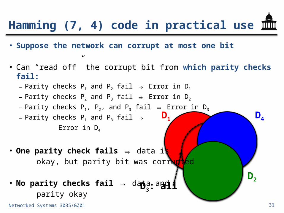
• Suppose the network can corrupt at most one bit
• Can “read off” the corrupt bit from which parity checks fail:– Parity checks P1 and P2 fail Error in D⇒ 1
– Parity checks P2 and P3 fail Error in D⇒ 2
– Parity checks P1, P2, and P3 fail Error in D⇒ 3
– Parity checks P1 and P3 fail ⇒
Error in D4
• One parity check fails data is⇒ okay, but parity bit was corrupted
• No parity checks fail data and ⇒ parity okay

32
Today
1. Error detecting and correcting codes2. Practical error control codes– Parity, and 2-D parity– Block codes: Hamming (7, 4) code– Polynomial codes: Cyclic redundancy check
3. The Internet checksum
Networked Systems 3035/GZ01

33
Error detection at the link layer: CRC• Problem: Errors overcome the PHY’s
error-control capability– Need error detection with a low
probability of missing an error
• Link layer (L2)– Cyclic Redundancy Check (CRC)– L2 CRC improves performance
• Quickly filters out corrupted frames
• Physical layer (PHY)– Forward Error Correction (FEC) or
Error Control Coding (ECC)
Networked Systems 3035/GZ01
PHY payload
LL header LL payload LL CRC
IC IP payload
IC TCP payload
IP header
TCP header

34
Cyclic redundancy check (CRC)
• Most popular method error detecting code at L2– Found in Ethernet, WiFi, token ring, many many others
• Often implemented in hardware at the link layer
• Represent k-bit messages as degree k − 1 polynomials– Each coefficient in the polynomial is either zero or one, e.g.:
1 0 1 1 1 0
k = 6 bits of message
Networked Systems 3035/GZ01
M(x) = 1x5 + 0x4 + 1x3 + 1x2 + 1x + 0

35
Modulo-2 arithmetic
• Addition and subtraction are both exclusive-or, without carry or borrow
Networked Systems 3035/GZ01
110 101110110
111110
1
011000
110
101Multiplication example: Division example:
1101101
000011010
110100101110
110

36
CRC at the sender• M(x) is our message of length k– e.g.: M(x) = x5 + x3 + x2 + x (k = 6)
• Sender and receiver agree on a generator polynomial G(x) of degree g − 1 (i.e., g bits)– e.g.: G(x) = x3 + 1 (g = 4)
1. Calculate padded message T(x) = M(x)∙xg−1
– i.e., right-pad with g − 1 zeroes– e.g.: T(x) = M(x)∙x3 = x8 + x6 + x5 + x4
Networked Systems 3035/GZ01
1 0 1 1 1 0
1 0 0 1
1 0 1 1 1 0 0 0 0

37
CRC at the sender
2. Divide padded message T(x) by generator G(x)– The remainder R(x) is the CRC:
Networked Systems 3035/GZ01
1 0 1 1 1 0 0 0 01 0 0 11
1 0 0 10 1 0 1
0 1
0 0 0 01 0 1 01 0 0 1
0 1 1 0
0
0 0 0 01 1 0 0
1 1
1 0 0 11 0 1 01 0 0 1
0 1 1 R(x) = x + 1

38
3. The sender transmits codeword C(x) = T(x) + R(x)– i.e., the sender transmits the original message with
the CRC bits appended to the end– Continuing our example, C(x) = x8 + x6 + x5 + x4 + x + 1
CRC at the sender
Networked Systems 3035/GZ01
1 0 1 1 1 0 0 1 1
39
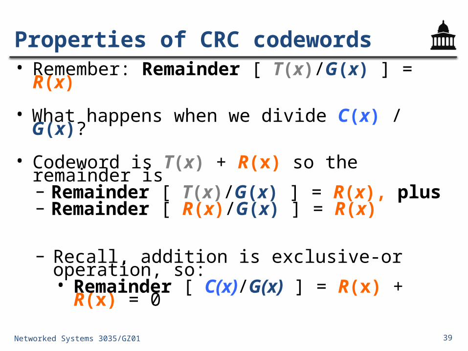
• Remember: Remainder [ T(x)/G(x) ] = R(x)
• What happens when we divide C(x) / G(x)?
• Codeword is T(x) + R(x) so the remainder is– Remainder [ T(x)/G(x) ] = R(x), plus – Remainder [ R(x)/G(x) ] = R(x)
– Recall, addition is exclusive-or operation, so:• Remainder [ C(x)/G(x) ] = R(x) + R(x) = 0
Properties of CRC codewords
Networked Systems 3035/GZ01

40
Detecting errors at the receiver
• Divide received message C′(x) by generator G(x)– If no errors occur, remainder will be zero
Networked Systems 3035/GZ01
1 0 1 1 1 0 0 1 11 0 0 11
1 0 0 10 1 0 1
0 1
0 0 0 01 0 1 01 0 0 1
0 1 1 0
0
0 0 0 01 1 0 1
1 1
1 0 0 11 0 0 11 0 0 1
0 0 0 no error detected

41
Detecting errors at the receiver
• Divide received message C′(x) by generator G(x)– If errors occur, remainder may be non-zero
Networked Systems 3035/GZ01
1 0 1 1 1 1 0 1 11 0 0 11
1 0 0 10 1 0 1
0 1
0 0 0 01 0 1 11 0 0 1
0 1 0 0
0
0 0 0 01 0 0 1
1 1
1 0 0 10 0 0 1 error detected

42
Detecting errors at the receiver
• Divide received message C′(x) by generator G(x)– If errors occur, remainder may be non-zero
Networked Systems 3035/GZ01
1 0 1 1 1 1 0 1 01 0 0 11
1 0 0 10 1 0 1
0 1
0 0 0 01 0 1 11 0 0 1
0 1 0 0
0
0 0 0 01 0 0 1
1 1
1 0 0 10 0 0 0 undetected error!
How many errors can the CRC detect?☟
How do we choose generator G(x)?

43
Detecting errors with the CRC• The error polynomial E(x) = C(x) + C′(x) is the difference
between the transmitted and received codeword– E(x) tells us which bits the channel flipped
• We can write the received message C′(x) in terms of C(x) and E(x): C′(x) = C(x) + E(x), so:– Remainder [C′(x) / G(x) ] = Remainder [ E(x) / G(x) ]
• When does an error go undetected?1. When Remainder [ E(x) / G(x) ] = 0, or2. When E(x) = G(x)∙Z(x) for some polynomial Z(x)
Networked Systems 3035/GZ01

44
Detecting single-bit errors with the CRC• Suppose a single-bit error in bit-position i: E(x) = xi
– Choose G(x) with ≥ 2 non-zero terms: xg−1 and 1
– Remainder [ xi / (xg−1 + + 1) ] ⋯ ≠ 0, e.g.:
• Therefore a CRC with this choice of G(x) always detects single-bit errors in the received message
Networked Systems 3035/GZ01
0 0 1 0 0 01 0 0 1
1
1 0 0 11

45
Implementing the CRC in hardware• Implemented in hardware at L2 using a shift register
• Shift register performs division– Think of time as discrete clock “ticks”– Every clock tick the register copies its input to its
storage and outputs what it stores– g−1 registers hold partial sum of each division step– Exclusive-or gates ⨁ subtract generator polynomial
Networked Systems 3035/GZ01
Padded message T(x)000x2 x1 x0x3

46
Implementing the CRC in hardware
• Register begins zero-initialized
• Shift T(x) in, one bit at a time– Each shift corresponds to one long-
division step
• A 1 is in the x3 register whenever 1 is in the quotient– The xor gate then “subtracts” G(x) (xor
gates placed in same pattern as 1’s in G(x))
Networked Systems 3035/GZ01
000x2 x1 x0
1 0 1 1 1 0 0 0 01 0 0 11 0 1 0
0 0 0 01 1 0 0
1 0 0 10 1 1 0
0 0 0 01 0 1 0
1 0 0 10 1 0 1
1 1
1 0 0 11 0 1 01 0 0 1
0 1 1
1 0 1 1 1 0 0 0 00 1 1 1 01 1 1 01 1 01 000 001 1 1
0 0 0
0 0 00 0 00 0 00 0 00 0 00 0 0x3

47
Error detecting properties of the CRC
• The CRC will detect:✔All single-bit errors
• Provided G(x) has two non-zero terms
– All burst errors of length ≤ g − 1• Provided G(x) begins with xg−1 and ends with 1• Similar argument to previous property
– All double-bit errors• With conditions on the frame length and choice of G(x)
– Any odd number of errors• Provided G(x) contains an even number of non-zero coefficients
Networked Systems 3035/GZ01

48
Common generators
• CRC-8: x8 + x2 + x + 1• CRC-10: x10 + x9 + x5 + x4 + x + 1• CRC-16: x16 + x15 + x2 + 1• CRC-CCITT: x16 + x12 + x5 + 1
• These generator polynomials meet certain properties:– At least two non-zero terms– Even number of non-zero coefficients
Networked Systems 3035/GZ01
49
Today
1. Error detecting and correcting codes2. Practical error control codes3. The Internet checksum
Networked Systems 3035/GZ01

50
L3/L4 error detection: the Internet Checksum
• Transport layer (L4)– Internet Checksum (IC) over TCP or UDP
header and data– End to end (E2E) checksum
• Network layer (L3)– Internet Checksum (IC) over IP header
only
• Link layer (L2)– Cyclic Redundancy Check (CRC)– L2 CRC improves performance
• Physical layer (PHY)– Forward Error Correction (FEC) or Error
Control Coding (ECC)Networked Systems 3035/GZ01
PHY payload
LL header LL payload LL CRC
IC IP payload
IC TCP payload
IP header
TCP header

51
Why another error detecting code?• Most errors are picked up at lower layers; this is the last
layer that can detect errors before the application itself– L2 corrects most errors with the CRC
• Implemented in software: simple and fast
• The only checksum that works end-to-end at the transport layer (L4)– Why is that important?
Networked Systems 3035/GZ01

52
Ones’ complement arithmetic• To represent x in ones’ complement:– If x is positive, write x in binary and prepend a zero• E.g. 510 = 0101
– If x is negative, write |x| in binary, negate it (complementing each bit), and prepend a one• E.g. −510 = 1010
• Notice that there are two ways to represent zero
• Addition uses carry and “end-around” carry: −5 − 3, e.g.:
1110: −110
1100: −310
1010: −510Networked Systems 3035/GZ01
1
1011:−410

53
• At the sender:1. Break packet into 16-bit words
(unsigned short or “ushort” data type)
2. Sum the words together using ones’ complement addition
3. Negate the result of the sum, and include in the relevant (IP or TCP) header field
• Receiver performs same calculation on received data– If result matches, receiver declares
that there are no errors
ushort cksum(ushort *buf, int count) {ulong sum = 0;while (count--) {
sum += *buf++;if (sum &
0xFFFF0000) {/* end-
around carry */sum = sum &
0xFFFF;sum++;
}}return ~(sum & 0x0000FFFF);
}
Internet checksum
Networked Systems 3035/GZ01
Internet checksum C code:

54
Internet checksum: Properties• Space efficient, using one word (16 bits) for any message length
• Recomputing checksum C after changing a single word m m′– Negate checksum, subtract m, add m , negate result′– New checksum C′ = ~(~C + ~m + m )′
• But, the Internet checksum has weaker error detection properties than the CRC:– Checksum is the negation of sum of data, so any single-bit error
in message or data is detectable– No guarantees beyond that an undetectable double-bit error:
Word #1: 0 … 0000 0101Word #2: 0 … 0000 0100#1 + #2: 0 … 0000 1001Checksum: 1 … 1111 0110
Networked Systems 3035/GZ01

55
NEXT TIME
Medium Access ControlPre-Reading: P & D Section 2.6 (5/e, 4/e)Pre-Reading: Ethernet Paper (PDF available online)
Networked Systems 3035/GZ01


