Martin Wilson Lecture 3 slide‹#› JUAS February 2016 Lecture 3: Magnets training and stability Magnets • magnetic fields above 2 Tesla • coil shapes for solenoids, dipoles and quadrupoles • engineering current density • load lines Degradation & Training • causes of training - release of energy within the magnet • reducing training - stability and minimum quench energy MQE • need copper and fine filaments for low MQE Flux Jumping • need for fine filaments the ATLAS magnet at CERN
Transcript
Martin Wilson Lecture 3 slide‹#› JUAS February 2016
Lecture 3: Magnets training and stability
Magnets
• magnetic fields above 2 Tesla
• coil shapes for solenoids, dipoles and quadrupoles
• engineering current density
• load lines
Degradation & Training
• causes of training - release of energy within the magnet
• reducing training - stability and minimum quench energy MQE
• need copper and fine filaments for low MQE
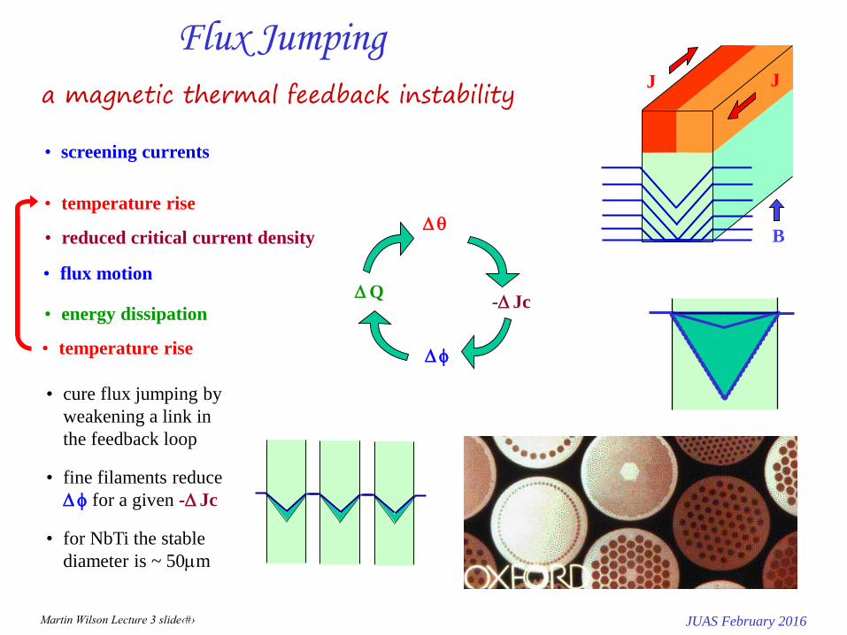
Flux Jumping
• need for fine filaments
the ATLAS magnet at CERN
Martin Wilson Lecture 3 slide‹#› JUAS February 2016
Fields and ways to create them: conventional
• conventional electromagnets have an iron yoke
- reduces magnetic reluctance
- reduces ampere turns required
- reduces power consumption
• iron guides and shapes the field I
I
B
100A/m-100A/m
1.6
T
H
-1.6T
B
Iron electromagnet
– for accelerators, motors,
transformers, generators etc
BUT iron saturates at ~ 2Tfor higher fields we cannot rely on iron
field must be created and shaped by the winding
Martin Wilson Lecture 3 slide‹#› JUAS February 2016
Solenoids
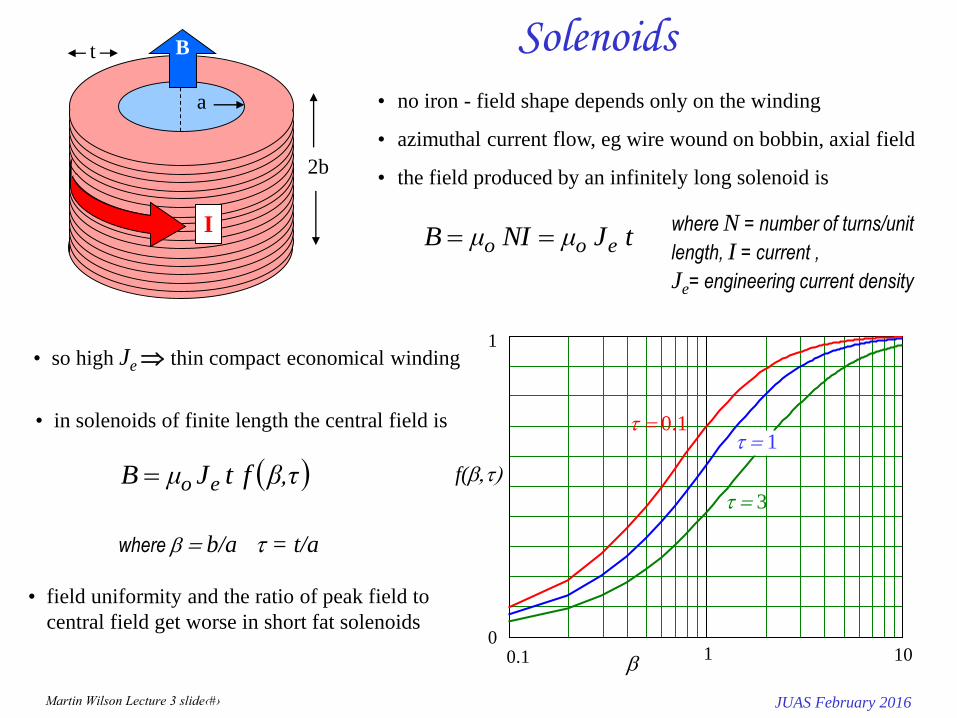
• no iron - field shape depends only on the winding
• azimuthal current flow, eg wire wound on bobbin, axial field
• the field produced by an infinitely long solenoid is
tJμNIμB eoo
B
I
2b
t
a
where N = number of turns/unit
length, I = current ,
Je= engineering current density
β,τftJμB eo
• in solenoids of finite length the central field is
• field uniformity and the ratio of peak field to
central field get worse in short fat solenoids
• so high Je thin compact economical winding
where b b/a t = t/a
0.1 1 100
0.1
0.2
0.3
0.4
0.5
0.6
0.7
0.8
0.9
1
0.995
0
F b 0.1( )
F b 1( )
F b 3.( )
100.1 bb
f(bt
1
010.1 10
t 0.1t 1
t 3
Martin Wilson Lecture 3 slide‹#› JUAS February 2016
Superconducting solenoids
Delphi solenoid for HEP experiments at CERN 1.2T 5.5m dia 6.8m long 110MJ
Superconducting
solenoid for
research
Martin Wilson Lecture 3 slide‹#› JUAS February 2016
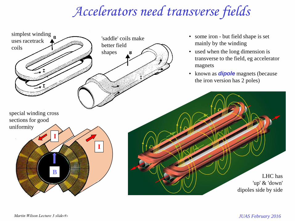
Accelerators need transverse fields
simplest winding
uses racetrack
coils
special winding cross
sections for good
uniformity
• some iron - but field shape is set
mainly by the winding
• used when the long dimension is
transverse to the field, eg accelerator
magnets
• known as dipole magnets (because
the iron version has 2 poles)
II
I
B
'saddle' coils make
better field
shapes
LHC has
'up' & 'down'
dipoles side by side
Martin Wilson Lecture 3 slide‹#› JUAS February 2016
B
B
J
Dipole field from overlapping cylinders
BB
J
Ampere's law for the field inside a cylinder carrying uniform current density
JrπμIμrB2πB.ds 2oo 2
rJB
o
BB
J
BB
B
J
B
JJ
BB
B
t t
J
q1 q2
r1
t
B
B
r2
B
B
J
2
tJμB eo
y
• thus the overlapping
cylinders give a
perfect dipole field
• two cylinders with opposite currents
• currents cancel where they overlap aperture
• fields in the aperture:
2
Jtμcosθrcosθr
2
JμB o
2211o
y
0sinθrsinθr2
JμB 2211
ox
• push them together
• same trick with ellipses
• circular aperture
Martin Wilson Lecture 3 slide‹#› JUAS February 2016
Windings of distributed current density Analyse thin current sheets flowing on the surface of a cylinder using complex algebra. Let the
linear current density (Amps per m of circumference) be gn(q) = go cos(nq (Am-1)
For n = 1 we find a pure dipole field inside the cylinder, n = 2 gives a quadrupole etc.
Now superpose many cylinders of increasing radius to get a thick walled cylinder carrying an
(area) current density (Am-2) Jn = Jo cos(nq
qq cos)( 01JJ
2/2/)( 00 tJabJB ooy 0xB
n=1 n=2 θJJ 2cos)( 02q
a
by
JB o
x ln2
0
a
bx
JB o
y ln2
0
a
b
t
B gradient
Martin Wilson Lecture 3 slide‹#› JUAS February 2016
Summary of simplified dipole windings
tJB oo
Overlapping circlesOverlapping ellipses
Cos (q 60° sector
tJ2
μB o
otJ
2
μB o
o
where c / (b +c)
c = height of ellipse
b = width
)Sin(60tJπ
2μB o
oo
t = winding thickness Jo =
engineering current density 0.55)Sin(60
π
2 o best estimate
of forces
best estimate of peak field
LHC dipole winding
B
I β,τftJμB eo
recap solenoid
B
Martin Wilson Lecture 3 slide‹#› JUAS February 2016
Importance of (engineering) current density in dipoles
field produced
by a perfect
dipole is
2
tJB eo
Je = 375 Amm-2
120mm
9.5x10⁵ Amp turns
Je = 37.5 Amm-2
9.5x10⁶ Amp turns
I
LHC dipole
660mm
I
I
B
Martin Wilson Lecture 3 slide‹#› JUAS February 2016
Dipole Magnets
II
I
B
Martin Wilson Lecture 3 slide‹#› JUAS February 2016
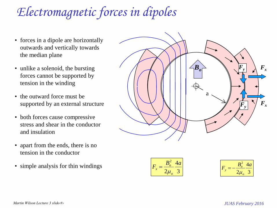
Electromagnetic forces in dipoles
• forces in a dipole are horizontally
outwards and vertically towards
the median plane
• unlike a solenoid, the bursting
forces cannot be supported by
tension in the winding
• the outward force must be
supported by an external structure
• both forces cause compressive
stress and shear in the conductor
and insulation
• apart from the ends, there is no
tension in the conductor
• simple analysis for thin windings
FxFy
FyFx
3
4
2
2 aBF
o
ox
3
4
2
2 aBF
o
oy
a
Bo
Martin Wilson Lecture 3 slide‹#› JUAS February 2016
Estimating the iron shield thicknessno iron
with iron
flux through ½ coil aperture fc Bo a
a = coil radius
t = iron thickness
return flux through iron (one side) fi Bsat t
so t ~ a Bo / Bsat
Martin Wilson Lecture 3 slide‹#› JUAS February 2016
Quadrupole windings
I
I
Bx(y) = ky By(x)= kx
Martin Wilson Lecture 3 slide‹#› JUAS February 2016
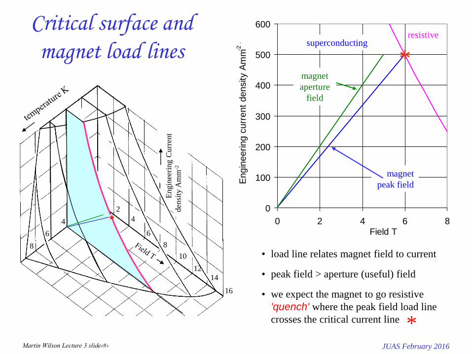
7Critical surface and
magnet load lines
8
6
4
2 2
4
6
8
10
12
14
16
En
gin
eeri
ng C
urr
ent
den
sity
Am
m-2
*0
100
200
300
400
500
600
0 2 4 6 8Field T
Engin
eering c
urr
ent
density A
mm -
2 .
*superconducting
resistive
magnet
peak field
magnet
aperture
field
• load line relates magnet field to current
• peak field > aperture (useful) field
• we expect the magnet to go resistive
'quench' where the peak field load line
crosses the critical current line *
Martin Wilson Lecture 3 slide‹#› JUAS February 2016
Degraded performance and ‘training’ of magnets
time
fiel
d
• early disappointment for magnet makers when they
ramped up the magnet current for the first time
• instead of going up to the critical line, it ‘quenched’
(went resistive) at less than the expected current
• at the next try it did better
• known as training
quench
• after a quench, the stored energy of the
magnet is dissipated in the magnet, raising
its temperature way above critical
• you must wait for it to cool down and then
try again
• well made magnets are better than
poorly made
0
50
100
150
200
250
0 5 10 15 20
quench number
qu
en
ch
cu
rre
nt
critical
Martin Wilson Lecture 3 slide‹#› JUAS February 2016
‘Training’ of magnets
Training of LHC short prototype dipoles (from A. Siemko)
• it's better than the
old days, but
training is still
with us
• it seems to be
affected by the
construction
technique of the
magnet
• it can be wiped
out if the magnet
is warmed to
room temperature
• 'de-training is the
most worrysome
feature
8.0
8.5
9.0
9.5
10.0
0 5 10 15 20 25 30 35 40 45
quench number
fie
ld a
ch
eiv
ed
.
stainless steel collars
stainless steel collars
aluminium collarsoperating field
Martin Wilson Lecture 3 slide‹#› JUAS February 2016
• the specific heat of all substances
falls with temperature
• at 4.2K, it is ~2,000 times less than
at room temperature
• a given release of energy within
the winding thus produce a
temperature rise 2,000 times
greater than at room temperature
• the smallest energy release can
therefore produce catastrophic
effects
4.2K
300K
102
102
10
10-1
10-2
1
Sp
ecif
ic H
eat
Jou
les
/ k
g /
K
1 10 100 1000temperature K
Causes of training:
(1) low specific heat
Martin Wilson Lecture 3 slide‹#› JUAS February 2016
6
7
1000
8
6
4
2 2
4
6
8
10
1214
16
200
400
En
gin
eeri
ng
Cu
rren
t den
sity
kA
mm
-2
*
10
600
800
6
7
1500
8
6
4
2 2
4
6
8
10
1214
16
300
600
En
gin
eeri
ng
cu
rren
t
den
sity
Am
m-2
-
*
10
900
1200
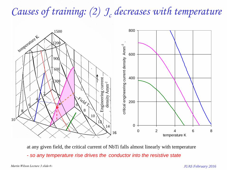
Causes of training: (2) Jc decreases with temperature
at any given field, the critical current of NbTi falls almost linearly with temperature
- so any temperature rise drives the conductor into the resistive state
0
200
400
600
800
0 2 4 6 8temperature K
cri
tica
l e
ng
ine
eri
ng
cu
rre
nt d
en
sity A
mm
-2 .
Martin Wilson Lecture 3 slide‹#› JUAS February 2016
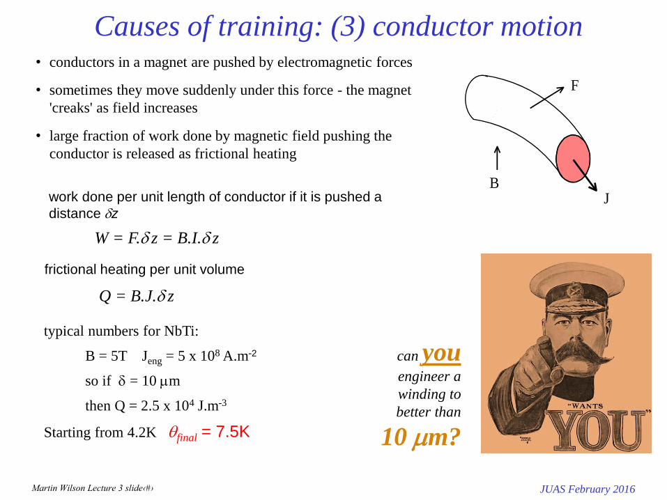
Causes of training: (3) conductor motion• conductors in a magnet are pushed by electromagnetic forces
• sometimes they move suddenly under this force - the magnet
'creaks' as field increases
• large fraction of work done by magnetic field pushing the
conductor is released as frictional heating
B
F
J
typical numbers for NbTi:
B = 5T Jeng = 5 x 10⁸ A.m-2
so if d = 10 m
then Q = 2.5 x 10⁴ J.m-3
Starting from 4.2K qfinal = 7.5K
work done per unit length of conductor if it is pushed a
distance dz
W = F.d z = B.I.d z
frictional heating per unit volume
Q = B.J.d z
can youengineer a
winding to
better than
10 m?
Martin Wilson Lecture 3 slide‹#› JUAS February 2016
Causes of training: (4) resin cracking
Calculate strain energy in resin caused by differential thermal contraction
s = tensile stress Y = Young’s modulus n = Poisson’s ratio
e = differential strain due to cooling = contraction (resin - metal)
typically: e = (11.5 – 3) x 10-3 Y = 7 x 10⁹ Pa n = 1/3
Try to stop wire movement by impregnating the winding with epoxy resin. But resin contracts more
than metal, so it goes into tension. Almost all organic materials become brittle at low temperature.
brittleness + tension cracking energy release
22
22
1
es Y
YQ
)21(2
3
2
)21(3 22
3n
ens
Y
YQ
Q1 = 2.5 x 10⁵ J.m-3
Q3 = 2.3 x 10⁶ J.m-3
uniaxial
strain
triaxial
strain
cracking releases most of this stored energy as heat
Interesting fact: magnets impregnated with paraffin wax show almost no training
although the wax is full of cracks after cooldown.
Presumably the wax breaks at low s before it has had chance to store up any strain energy
qfinal = 16K
qfinal = 28K
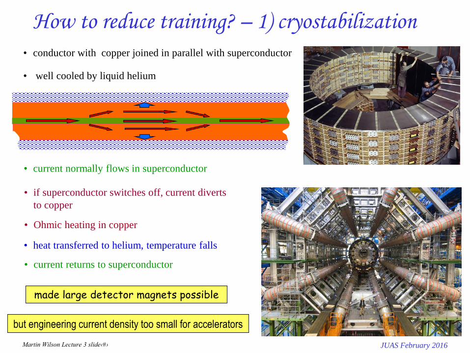
How to reduce training? – 1) cryostabilization
• conductor with copper joined in parallel with superconductor
• well cooled by liquid helium
• current normally flows in superconductor
• if superconductor switches off, current diverts
to copper
• Ohmic heating in copper
• current returns to superconductor
• heat transferred to helium, temperature falls
made large detector magnets possible
but engineering current density too small for accelerators
Martin Wilson Lecture 3 slide‹#› JUAS February 2016