18
1 EE4900/EE6720 Digital Communications Suketu Naik EE4900/EE6720: Digital Communications Lecture 3 Review of Signals and Systems: Part 2
1
EE4900/EE6720 Digital Communications Suketu Naik
EE4900/EE6720: Digital Communications
Lecture 3
Review of
Signals and Systems:
Part 2
2
EE4900/EE6720 Digital Communications Suketu Naik
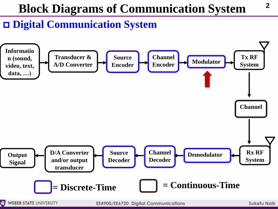
Block Diagrams of Communication System
Digital Communication System
Informatio
n (sound,
video, text,
data, …)
Transducer &
A/D ConverterModulator
Source
Encoder
Channel
Encoder
Tx RF
System
Output
Signal
D/A Converter
and/or output
transducer
DemodulatorSource
Decoder
Channel
Decoder
Rx RF
System
Channel
= Discrete-Time = Continuous-Time
3
EE4900/EE6720 Digital Communications Suketu Naik
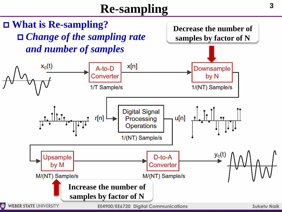
Re-sampling
What is Re-sampling?
Change of the sampling rate
and number of samples
Decrease the number of
samples by factor of N
Increase the number of
samples by factor of N
4
EE4900/EE6720 Digital Communications Suketu Naik
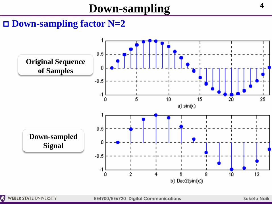
Down-sampling
Down-sampling factor N=2
Original Sequence
of Samples
Down-sampled
Signal
5
EE4900/EE6720 Digital Communications Suketu Naik
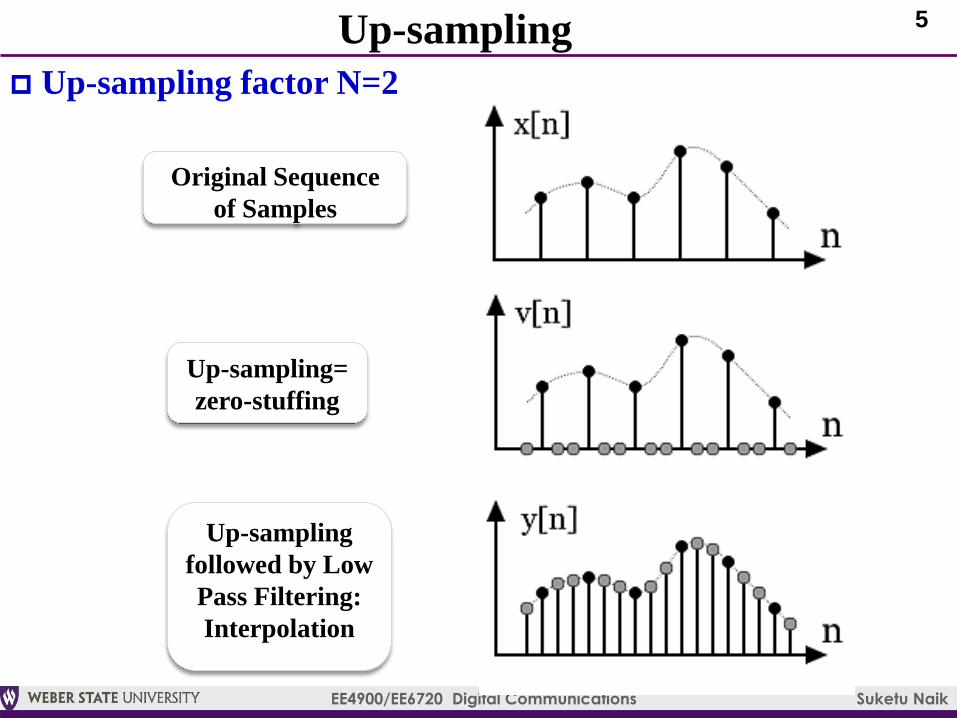
Up-sampling
Up-sampling factor N=2
Original Sequence
of Samples
Up-sampling=
zero-stuffing
Up-sampling
followed by Low
Pass Filtering:
Interpolation
6
EE4900/EE6720 Digital Communications Suketu Naik
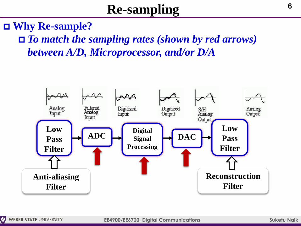
Re-sampling
Why Re-sample?
To match the sampling rates (shown by red arrows)
between A/D, Microprocessor, and/or D/A
Digital
Signal
Processing
Low
Pass
Filter
ADCLow
Pass
Filter
DAC
Anti-aliasing
Filter
Reconstruction
Filter
7
EE4900/EE6720 Digital Communications Suketu Naik
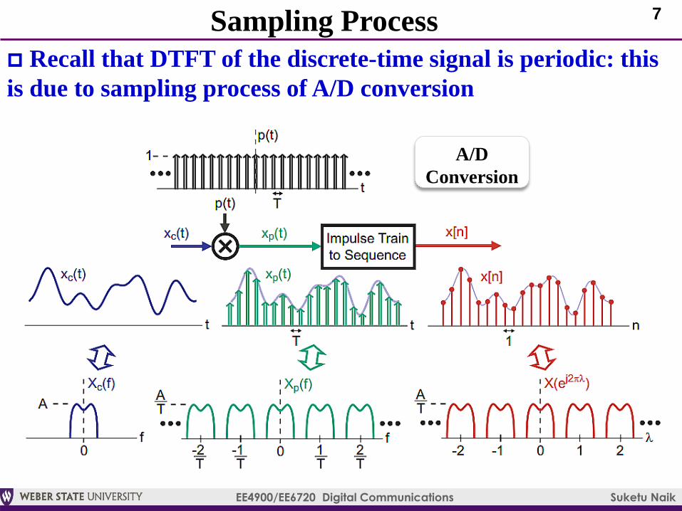
Sampling Process
Recall that DTFT of the discrete-time signal is periodic: this
is due to sampling process of A/D conversion
A/D
Conversion
8
EE4900/EE6720 Digital Communications Suketu Naik
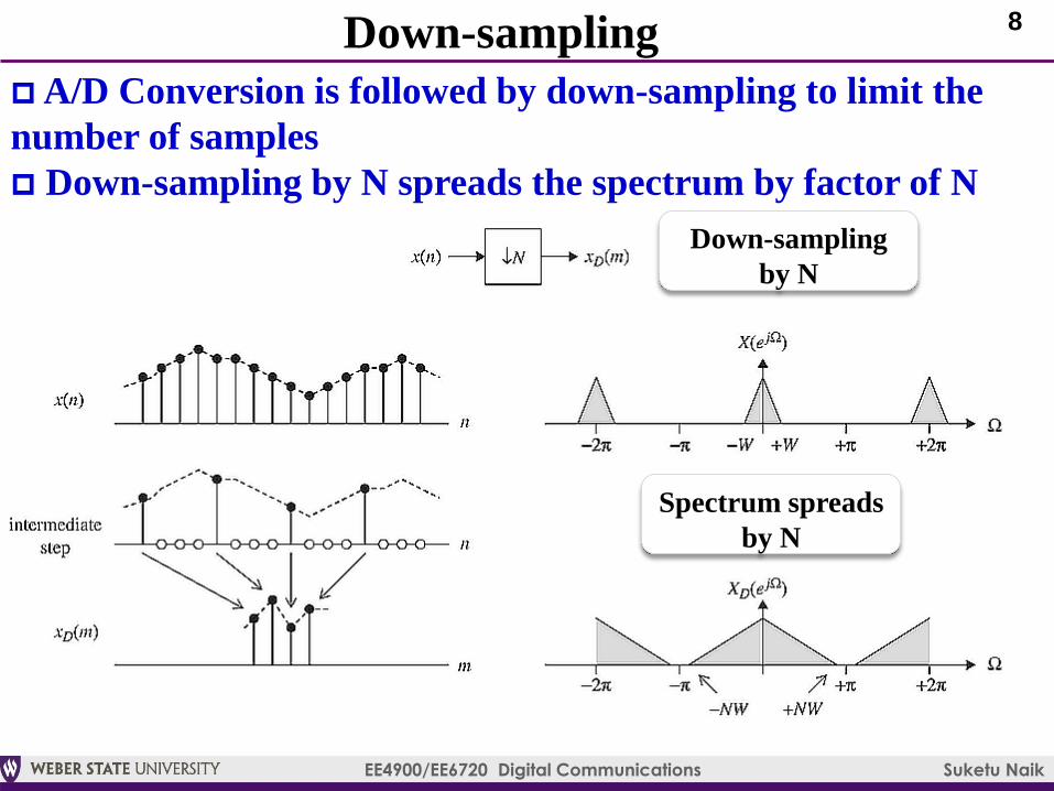
Down-sampling
A/D Conversion is followed by down-sampling to limit the
number of samples
Down-sampling by N spreads the spectrum by factor of N
Down-sampling
by N
Spectrum spreads
by N
9
EE4900/EE6720 Digital Communications Suketu Naik
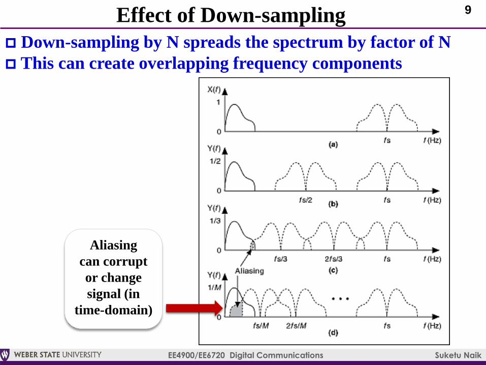
Effect of Down-sampling
Down-sampling by N spreads the spectrum by factor of N
This can create overlapping frequency components
Aliasing
can corrupt
or change
signal (in
time-domain)
10
EE4900/EE6720 Digital Communications Suketu Naik
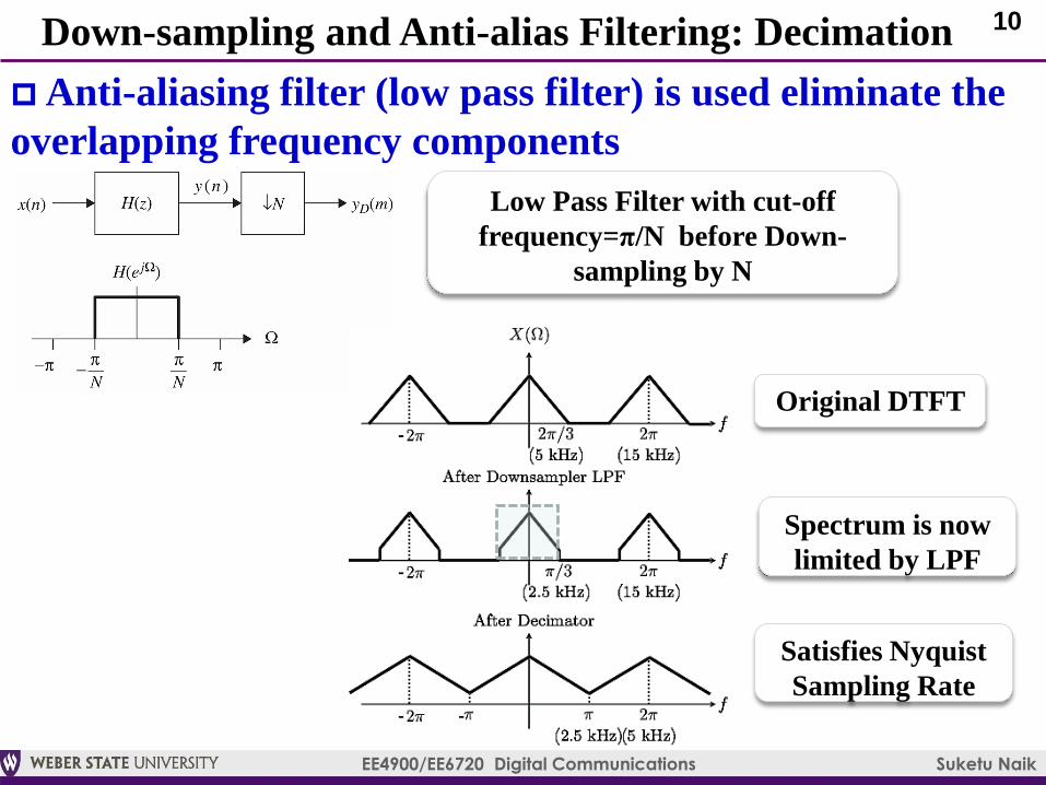
Down-sampling and Anti-alias Filtering: Decimation
Anti-aliasing filter (low pass filter) is used eliminate the
overlapping frequency components
Low Pass Filter with cut-off
frequency=π/N before Down-
sampling by N
Spectrum is now
limited by LPF
Original DTFT
Satisfies Nyquist
Sampling Rate
11
EE4900/EE6720 Digital Communications Suketu Naik
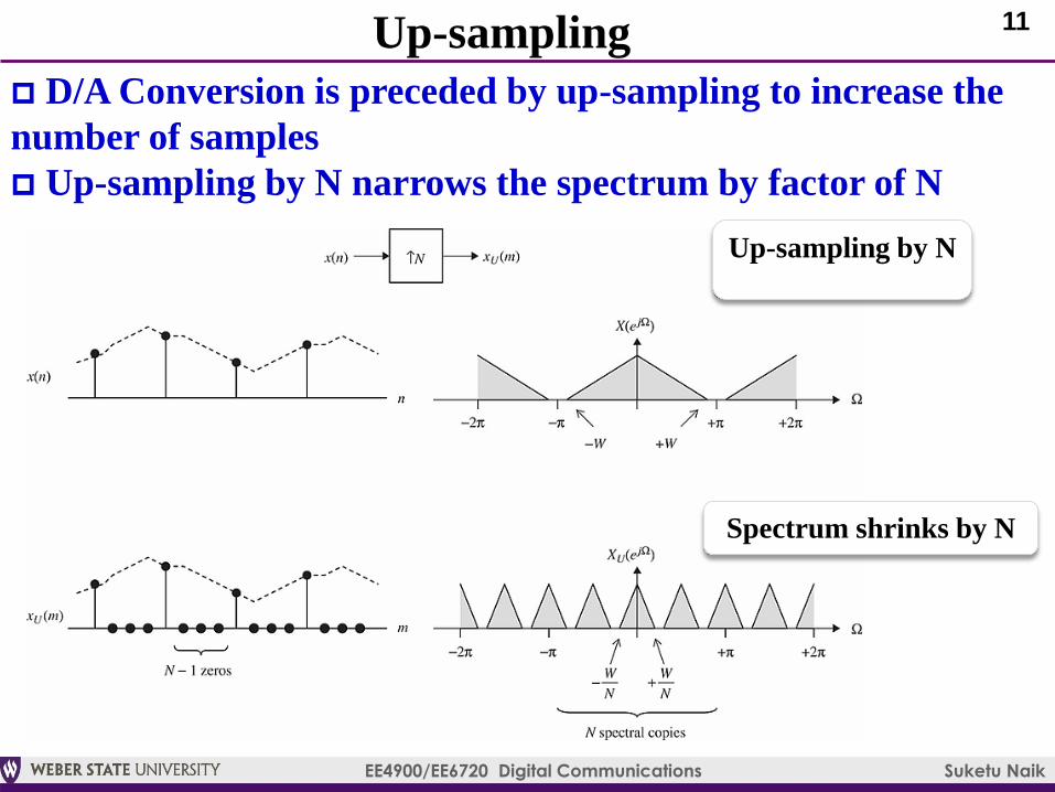
Up-sampling
D/A Conversion is preceded by up-sampling to increase the
number of samples
Up-sampling by N narrows the spectrum by factor of N
Up-sampling by N
Spectrum shrinks by N
12
EE4900/EE6720 Digital Communications Suketu Naik
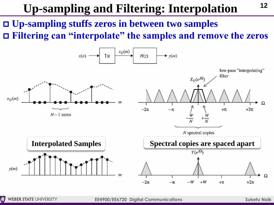
Up-sampling and Filtering: Interpolation
Up-sampling stuffs zeros in between two samples
Filtering can “interpolate” the samples and remove the zeros
Interpolated Samples Spectral copies are spaced apart
13
EE4900/EE6720 Digital Communications Suketu Naik
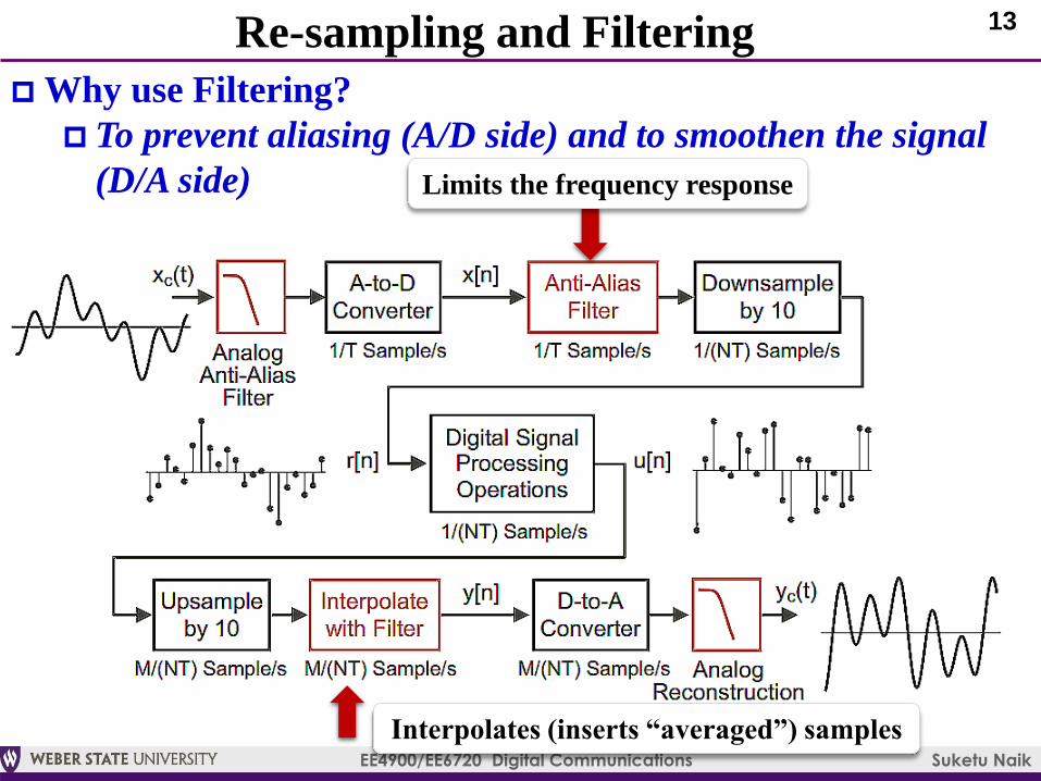
Re-sampling and Filtering
Why use Filtering?
To prevent aliasing (A/D side) and to smoothen the signal
(D/A side) Limits the frequency response
Interpolates (inserts “averaged”) samples
14
EE4900/EE6720 Digital Communications Suketu Naik
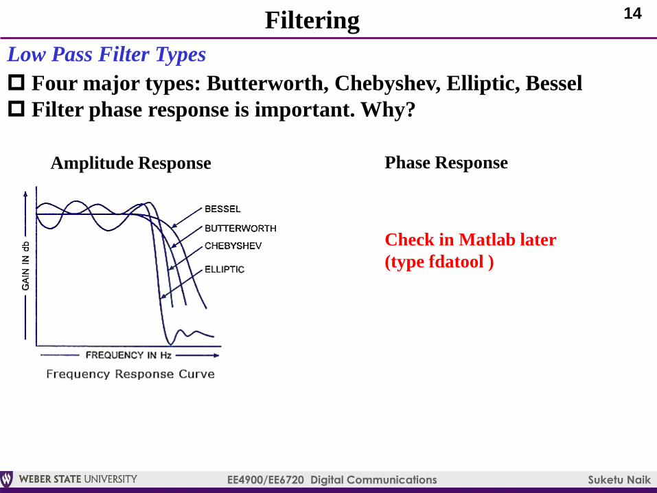
Filtering
Low Pass Filter Types
Four major types: Butterworth, Chebyshev, Elliptic, Bessel
Filter phase response is important. Why?
Amplitude Response Phase Response
Check in Matlab later
(type fdatool )
15
EE4900/EE6720 Digital Communications Suketu Naik
Linear Constant-coefficient Difference Equation
Input and output relationship of discrete-time system: Eq. 2.24
Suppose that
1) Input signal samples are denoted by x(n) and output by y(n)
1) The filter coefficients are denoted by numerator b0, …, bM and
denominator a0, …, aM with filter order=M
Eq. 3.18: Infinite Impulse Response (IIR) Filter
Eq. 3.29: Finite Impulse Response (FIR) Filter
16
EE4900/EE6720 Digital Communications Suketu Naik
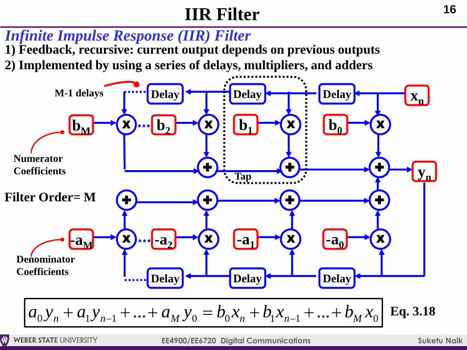
IIR Filter
Infinite Impulse Response (IIR) Filter1) Feedback, recursive: current output depends on previous outputs
2) Implemented by using a series of delays, multipliers, and adders
Tap
X
+
Delay
bM
xn
Xb2
+
Delay
Xb1...
+
Delay
Xb0
yn
Numerator
Coefficients
01100110 ...... xbxbxbyayaya MnnMnn
M-1 delays
Filter Order= M
X
+
Delay
-aMX-a2
+
Delay
X-a1
+
Delay
X-a0
Denominator
Coefficients
...
+
Eq. 3.18
17
EE4900/EE6720 Digital Communications Suketu Naik
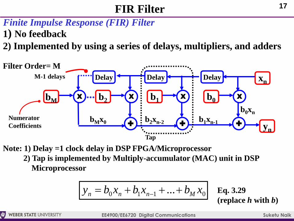
FIR Filter
Finite Impulse Response (FIR) Filter
1) No feedback
2) Implemented by using a series of delays, multipliers, and adders
Tap
X
+
Delay
bM
xn
Xb2
+
Delay
Xb1...
+
Delay
Xb0
yn
Numerator
Coefficients
0110 ... xbxbxby Mnnn
M-1 delays
Filter Order= M
b0xn
b1xn-1b2xn-2bMx0
Note: 1) Delay =1 clock delay in DSP FPGA/Microprocessor
2) Tap is implemented by Multiply-accumulator (MAC) unit in DSP
Microprocessor
Eq. 3.29
(replace h with b)
18
EE4900/EE6720 Digital Communications Suketu Naik
Assignment 1
Design FIR Filter using FDATOOL
Simulate Up-sampling and Down-sampling in Simulink
Submit the following:
1) Filter Magnitude and Phase Response Plots
2) Simulink model(s)
3) Time-domain plots
4) Frequency domain plots


