66
Lecture 4 Global System for Mobile Communications (GSM) Asad Ali

Lecture 4
Global System for Mobile Communications (GSM)
Asad Ali

GSM system overview
� GSM is a digital wireless network � It provides a common set of compatible services and capabilities
to all mobile users worldwide� The basic requirements of GSM have been described in five
aspects:� Services:� The system will provide service portability, that is, mobile � The system will provide service portability, that is, mobile
phones can be used in all participating countries. The system will offer services that exist in fixed line networks as services specific to mobile communications
� Quality of service and Security:� The quality of voice telephony of GSM will be at least as good
as the previous analog systems over the operating range. The system will be capable of offering information encryption without significantly affecting costs to users who do not require such facility.

GSM system overview
� Radio frequency utilization:
� The system will permit high level of spectrum efficiency and state-of-the-art user facilities. The system will be capable of operating in the entire allocated frequency band and co-exist with the earlier systems using the same frequency.
� Network:� Network:
� The identification and numbering plans will be based on relevant ITU recommendations.
� Cost:
� System parameters will be chosen with a view to limiting the cost of the complete system in particular the Mobile Stations.
� The figure in the next slide illustrates the GSM architecture.

GSM architecture

GSM architecture

GSM architecture (2)
� MS Mobile Station
� Base Station Subsystem (BSS)
� BTS: Base Transceiver station
� BSC: Base Station Controller
� Network and Switching Subsystem (NSS)� Network and Switching Subsystem (NSS)
� MSC: Mobile Switching center
� Registers: HLR (Home Location Register), VLR (Visitor
Location Register, AuC (Authentication center), EIR
(Equipment Identity Register)
� GMSC: Gateway Services Switching Center

GSM Frequencies
� GSM-900
� Uplink: 890 – 915 MHz (25 MHz)
� Downlink: 935 – 960 MHz (25 MHz)
� Uplink - Downlink distance: 45 MHz
� FDMA
� Channels are 200 kHz wide
� Use 124 pairs of channels
� TDMA
� 8 timeslots (connections) on each channel
� Theoretical 124*8 = 992 channels to use

Mobile Station (MS)
� The MS consists of two parts:
� Subscriber Identity Module (SIM) and the Mobile
Equipment (ME)
� The SIM is protected by the Personal Identity Number
(PIN) which is usually 4 digits in length(PIN) which is usually 4 digits in length
� To use the MS, the user is asked to enter the PIN
� If the number is not correctly entered in 3 attempts, the
SIM is blocked and the MS cannot be used
� To unblock the SIM, the user is asked to enter the eight
digit PIN unblocking key (PUK)

Mobile Station (MS)
� A SIM card is a small memory device which contains user
specific information
� It can be taken out from one mobile and inserted into
another
� In a GSM network, the SIM card identifies the user – just � In a GSM network, the SIM card identifies the user – just
like a traveler uses a passport to identify himself
� There is also a storage place for messages and store
phone numbers
� A home operator issues a SIM card when the user joins
the network by making a service subscription
� It also contains tools for authentication purposes.

The Base Station Subsystem (BSS)
� The BSS connects the MS and the Network and Switching Subsystem (NSS)
� It consists of two parts:
� Base Transceiver Station (BTS)
� Base Station Controller (BSC)
The BTS contains transmitter, receiver and signaling � The BTS contains transmitter, receiver and signaling equipment related to the air interface in order to contact the MS
� The BSC is responsible for switching functions in the BSS and it turn connected to an Mobile Switching Center (MSC) in the NSS
� The BSS also supports channel allocation/ release and handover management.

Network and Switching Subsystem (NSS)
� The NSS contains the MSC, HLR, VLR, AuC and EIR.
� It supports switching functions, user profiles and mobility management.
� Basic switching functions in the NSS are performed by the MSC
� User information relevant to the provisioning of services is kept in the HLR
� User information relevant to the provisioning of services is kept in the HLR
� When an MS moves from its current location to a visited location, its location is registered at the VLR of that system. The VLR then informs the HLR of its current location
� The Authentication Center (AuC) is used in security data management for the authentication of users. The AuC maybe co-located with the HLR.

Network and Switching Subsystem (NSS)
� The Equipment Identity Register (EIR) is a database
which stores all device identifications registered for a
network
� As MSs are mobile, they can easily be stolen. With a
valid SIM, anyone could use the stolen MSvalid SIM, anyone could use the stolen MS
� The EIR has a blacklist of stolen devices.
� The MSC is involved in the interworking functions to
communicate with other networks such as the PSTN
through the GMSC.

Mobile Switching Center (MSC)
� Responsible for controlling calls within the network
� An MSC acting as a bridge between a mobile network and other fixed networks is known as Gateway MSC (GMSC)
� The MSC is responsible for several important tasks
� Call control: The MSC identifies the type of the call, its origin and destination. It also sets up, supervises and clear and destination. It also sets up, supervises and clear connections.
� Initiation of Paging: Paging is the process of locating a mobile in case of a mobile terminated call (MTC) (a call to a mobile station).
� Charging: Collects charging information about the call such as the number of callers and the called subscribers, the time and type of transaction etc and transfers it to the Billing Center.

Home Location Register (HLR)
� The HLR is the most important database in a GSM network.
� It stores all user relevant information
� This comprises of International Mobile Subscriber Identity (IMSI), Mobile Subscriber ISDN number (MSISDN), user data (e.g. supplementary services).
� It also stores dynamic information such as the current location � It also stores dynamic information such as the current location area (LA) of the MS, the Mobile Subscriber Roaming Number (MSRN), current VLR and MSC
� As soon as the MS leaves its current LA, the information in the HLR is updated . This information is necessary to localize a user in the worldwide GSM network.
� HLRs can manage data for several million users and it contains highly specialized databases.
What is IMSI, TMSI, MSISDN, MSRN, IMEI
etc.. ?
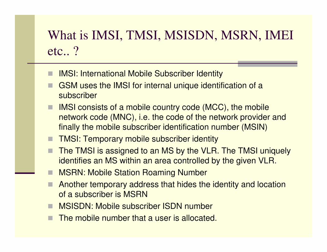
� IMSI: International Mobile Subscriber Identity
� GSM uses the IMSI for internal unique identification of a subscriber
� IMSI consists of a mobile country code (MCC), the mobile network code (MNC), i.e. the code of the network provider and finally the mobile subscriber identification number (MSIN)finally the mobile subscriber identification number (MSIN)
� TMSI: Temporary mobile subscriber identity
� The TMSI is assigned to an MS by the VLR. The TMSI uniquely identifies an MS within an area controlled by the given VLR.
� MSRN: Mobile Station Roaming Number
� Another temporary address that hides the identity and location of a subscriber is MSRN
� MSISDN: Mobile subscriber ISDN number
� The mobile number that a user is allocated.

What is IMSI, MSISDN, MSRN, IMEI etc.. ?
� The VLR generates this address on the request of the MSC and this is also stored in the HLR.
� MSRN contains the current visitor country code (VCC), the visitor national destination code (VNDC), the identification of the current MSC together with the subscriber number.
� The MSRN helps the HLR to find a subscriber for an incoming call.call.
� IMEI: International Mobile Equipment Identity� The IMEI uniquely identifies the MS equipment. It is assigned by
the equipment manufacturer. The IMEI contains 15 digits and carries
� Type Approval code (TAC): 6 digits� Final Assembly Code (FAC): 2 digits� Serial Number (SN): 6 digits� A Spare (SP): 1 digit

Visitor Location Register (VLR)
� A VLR is integrated with an MSC
� It’s a dynamic data base which contains information about subscribers currently being in the service area of an MSC/VLR such as:
� Identification numbers of subscribers
� Security information for authentication of the SIM card� Security information for authentication of the SIM card
� Services that the subscriber can use
� The VLR carries out location registration and updates. It means that when a mobile station comes to a new MSC/VLR serving area, it must register itself with the VLR, in other words, perform a location update.
� It’s a temporary database and holds to information as long as the MS is in its serving area.

Authentication Center (AuC)
� Provides security information to the network so that we
can verify the SIM card (authentication between the MS
and the VLR)
� Supports the VLR work

Equipment Identity Register (EIR)
� The EIR is also used for security reasons.
� It is responsible for the IMEI checking (checking the
validity of the mobile equipment)
� The EIR contains three lists:
� A mobile equipment in the white list is allowed to operate � A mobile equipment in the white list is allowed to operate
normally
� If we suspect that the mobile equipment is faulty, we can
monitor the use of it. It is then placed in the grey list
� If the mobile equipment is reported stolen, or it is
otherwise not allowed to operate in the network, it is
placed in the black list.

Radio Interface
� The available frequency band is divided into two sub
bands:
� UPLINK and DOWNLINK

Radio Interface
� FDM is used to separate both the uplink and downlink as
shown below.

Radio Interface
� This makes it 124 pairs of 248 channels.
� Each of the 248 channels are additionally separated in time via a GSM TDMA frame, i.e. each 200 kHz carrier is subdivided into frames that are repeated continuously.continuously.
� The duration of the frame is 4.615 ms
� A TDMA frame is again divided into 8 GSM timeslots where each slot represents a physical TDM channel and lasts for 577 microseconds
� Each TDM channel occupies the 200 kHz for 577 microseconds every 4.615 ms.

Radio Interface
� Data is transmitted in small portions called bursts
� The figure in the next slide shows the so-called
normal burst as used in data transmission inside a
time slot.
� In the diagram, the burst is only 546.5 microseconds � In the diagram, the burst is only 546.5 microseconds
long and contains 148 bits
� The remaining 30.5 microseconds are used as guard
space to avoid overlapping with other bursts
� Filling the whole slot with data allows for the
transmission of 156.25 bits within 577 microseconds

Radio Interface

Radio Interface
� The tail bits (T) are a group of 3 bits set to zero and placed
at the beginning and the end of a burst. They cover the
periods of ramping up and down of the mobile's power.
� The user data bits corresponds to two groups, of 57 bits
each, containing signaling or user data.
� The stealing flags (S) indicate, to the receiver, whether the � The stealing flags (S) indicate, to the receiver, whether the
data bits are data or signaling traffic.
� The training sequence has a length of 26 bits. It
synchronizes the receiver, thus masking out multi-path
propagation effects.
� The guard period (GP), with a length of 8.25 bits, is used to
avoid a possible overlap of two mobiles during the ramping
time

Logical Channels and Frame Hierarchy
� The air interface has two sorts of channels, i.e. physical
channels and logical channels
� One channel is the highway that carries the signal traffic
� The other is the traffic that flows along the highway
� Which is the physical and logical channel in the next � Which is the physical and logical channel in the next
figure.
� Physical channel?
� Logical channel?

Logical Channels and Frame Hierarchy

Logical Channels and Frame Hierarchy
� Physical channel is the medium along which the
information is carried
� For terrestrial interfaces, this is usually cable
� For the air interface, these are radio waves
� Logical channels comprise the information that is
carried along the physical channel, that is, the traffic
itself

Logical Channels and Frame Hierarchy
� A single GSM Absolute Radio Frequency Channel
Number (ARFCN) can support up to 8 mobile users at the
same time

Logical Channels and Frame Hierarchy
� 8 consecutive physical channels or time slots occupy the
ARFCN for exactly one eighth of the time
� The 8 time slot sequence is called a TDMA frame
� Signals are carried in bursts from the MS to the BTS using
one time slot per TDMA frame (shown in the next slide)one time slot per TDMA frame (shown in the next slide)
� Subsequent data bursts occupy the same time slots
across successive TDMA frames
� Each time slot is a physical channel carrying varying
number of logical channels from the MS to the BTS
� Each user occupies the same physical channel until it
terminates the call or is handed over to another cell.

Logical Channels and Frame Hierarchy

Logical Channels and Frame Hierarchy
� Now we look into more detail on GSM logical channels
� GSM logical channels consists of Traffic Channels (TCH)
and Control Channels (CCH)
� GSM uses TCH to transmit user data
� Two basic categories of TCHs have been defined, i.e. full-� Two basic categories of TCHs have been defined, i.e. full-
rate TCH (TCH/F) and half-rate TCH (TCH/H)
� TCH/F is 22.8 kbps
� TCH/H is 11.4 kbps
� For data transmission, rates of 9.6, 4.8 and 2.4 kbps can
be used.

GSM Logical Channels
� There are two types of CCH associated with the TCH
� Slow Associated Control Channel (SACCH)
� Fast Associated Control Channel (FACCH)
� SACCH: A GSM control channel used by the MS for reporting signal strengths and quality measurements
� FACCH: Carries control information as shall be seen later� FACCH: Carries control information as shall be seen later
� Control channels in GSM are used to control medium access, allocation of traffic channels or mobility management and fall into three categories
� Broadcast Control Channels (BCCH)
� Common Control Channels (CCCH)
� Dedicated Control Channels (DCCH)

GSM Control Channels
� Broadcast Control Channels (BCCH)� A BTS uses this channel to signal information to all MSs within a
cell� Information transmitted in this channel is, for example,
frequencies available inside the cell and in neighboring cells. � The BTS sends information regarding frequency via the
frequency control channels (FCCH) and information about time frequency control channels (FCCH) and information about time synchronization via the synchronization channel (SCH) where both channels are sub-channels of the BCCH
� Downlink only� Carries information about the network, mobile’s present call and
the surrounding cells� The synchronizing channels carry frame synchronization
information� The Frequency control channels (FCCH) carries information
regarding frequency synchronization

Broadcast Control Channels (BCCH)

Common Control Channels (CCCH)
� Bi-directional
� All information regarding the connection setup between the MS and the BTS is exchanged via the CCCH
� For call towards an MS, the BTS uses paging channel (PCH) for paging the appropriate MS (downlink)
� If an MS wants to setup a call, it uses RACH to send data to the � If an MS wants to setup a call, it uses RACH to send data to the BTS (uplink) – gain access to the system
� The BTS uses access grant channel (AGCH) to signal an MS that it can use a TCH or SDCCH for further connection setup (downlink)
� PCH and AGCH are downlink but are never used at the same time
� Cell broadcast channel is used to transmit information such as traffic information to all MSs

Types of CCCHs

Dedicated Control Channels (DCCHs)
� Supported in GSM for dedicated use by specific MS� Its consists of� Standalone dedicated control channel (SDCCH)� Slow associated control channel (SACCH)� Fast associated control channel (FACCH)
� SDCCH: As long as an MS has not established a TCH with the BTS, it uses the SDCCH for signaling
� SACCH: Each TCH and SDCCH has a SACCH associated with it which is used to exchange system information, such as the channel quality and signal power level.
� FACCH: If more signaling information is needed to be transmitted and a TCH already exists, GSM uses the FACCH. The FACCH uses timeslots which are otherwise used by the TCH. This is necessary incase of handovers where the BTS and MS have to exchange data.

Types of Control Channels

GSM call origination (radio aspect)
RACH (request signaling channel
AGCH (assign signaling channel)
SDCCH (request call setup)
SDCCH (assign TCH)
FACCH (complete assignment)
SDCCH message exchanges for call setup
MS BSS
GSM call origination (radio aspect)
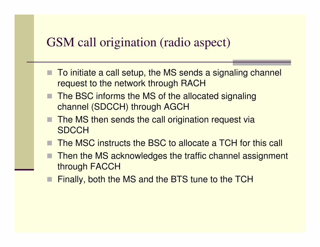
� To initiate a call setup, the MS sends a signaling channel
request to the network through RACH
� The BSC informs the MS of the allocated signaling
channel (SDCCH) through AGCH
� The MS then sends the call origination request via � The MS then sends the call origination request via
SDCCH
� The MSC instructs the BSC to allocate a TCH for this call
� Then the MS acknowledges the traffic channel assignment
through FACCH
� Finally, both the MS and the BTS tune to the TCH
Location Tracking and Call Setup
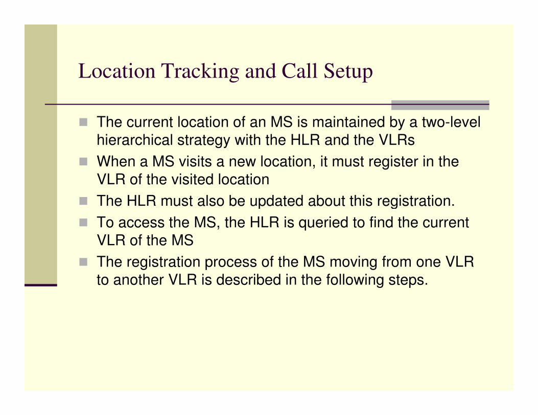
� The current location of an MS is maintained by a two-level
hierarchical strategy with the HLR and the VLRs
� When a MS visits a new location, it must register in the
VLR of the visited location
� The HLR must also be updated about this registration. � The HLR must also be updated about this registration.
� To access the MS, the HLR is queried to find the current
VLR of the MS
� The registration process of the MS moving from one VLR
to another VLR is described in the following steps.
The MS registration process

The MS registration process
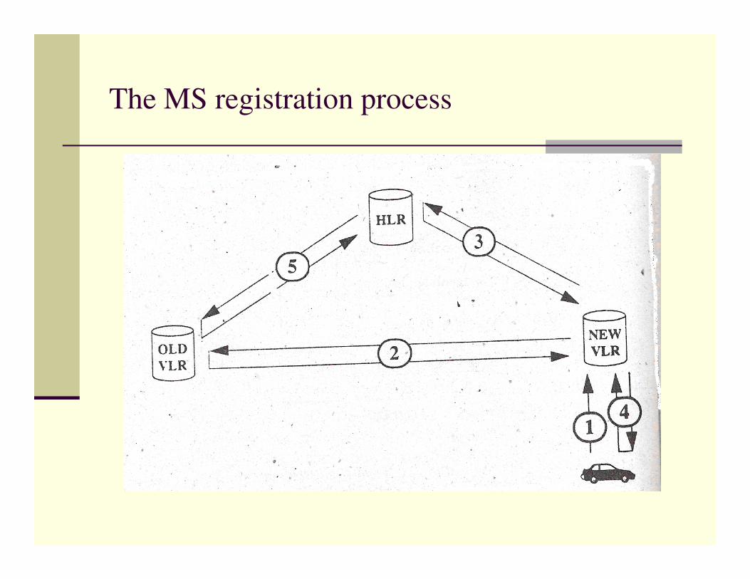
� Step1: The MS periodically listens to the BCCH broadcast from the BSS. If the MS detects that it has entered a new location area, it sends a registration message to the new VLR by using the SDCCH channel
� Step2: The new VLR communicates with the old VLR to � Step2: The new VLR communicates with the old VLR to get information about the MS. The new VLR then performs the authentication process to be described later
� Step3: After the MS is authenticated, the new VLR sends a registration message to the HLR. If the registration request is accepted, the HLR provides the new VLR with all relevant user information for call handling.

The MS registration process
� Step4: The new VLR informs the MS of the successful
registration
� Step5: After step 3, the HLR sends a deregistration
(cancellation) message to the old VLR. The old VLR (cancellation) message to the old VLR. The old VLR
cancels the record for the MS and sends an
acknowledgement to the HLR for the cancellation.
Localization
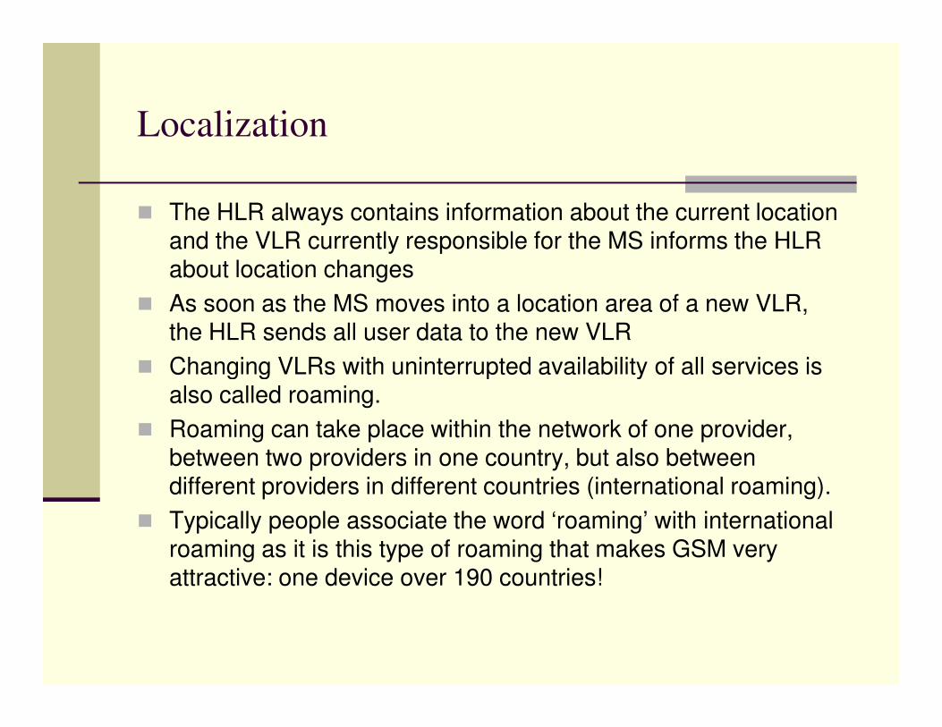
� The HLR always contains information about the current location and the VLR currently responsible for the MS informs the HLR about location changes
� As soon as the MS moves into a location area of a new VLR, the HLR sends all user data to the new VLR
� Changing VLRs with uninterrupted availability of all services is � Changing VLRs with uninterrupted availability of all services is also called roaming.
� Roaming can take place within the network of one provider, between two providers in one country, but also between different providers in different countries (international roaming).
� Typically people associate the word ‘roaming’ with international roaming as it is this type of roaming that makes GSM very attractive: one device over 190 countries!

Localization
� To locate an MS and to address the MS, several numbers
are needed:
� MSISDN: The only important number for a GSM user is
the phone number. The phone number is not associated the phone number. The phone number is not associated
with a certain device but with the SIM, which is
personalized for a user. The MSISDN follows the ITU-T
standard E.164 for addresses as it is also used for fixed
networks. This number consists of the country code,
national destination code (NDC) (i.e. address of the
network provider), and the subscriber number (SN).

Localization
� IMSI: GSM uses the IMSI for internal unique identification
of the user. IMSI consists of a mobile country code (MCC),
the mobile network code (MNC), and finally the mobile
subscriber identification number (MSIN).
� TMSI: To hide the IMSI, which would give away the exact
identity of the user over the air interface, GSM uses the 4
bit TMSI for local user identification. TMSI is selected by
the current VLR and is only valid temporarily and within
the location area of the VLR.

Localization
� MSRN: Another temporary address that hides the identity
and location of the user is the MSRN. The VLR generates
this address on request from the MSC and the address is
also stored in the HLR. MSRN contains the Visitor Country
Code (VCC), the visitor national destination code (VNDC),
the identification of the current MSC together with the user the identification of the current MSC together with the user
number.
� All these numbers are needed to find a subscriber and
maintain a connection with the MS.

Mobile Originated Call (MOC)
� Step 1: The MS transmits a request for a new connection
� Step 2: The BSS forwards this request to the MSC
� Step 3 and 4: The MSC then checks if this user is allowed
to setup a call with the requested service and checks the
availability of resources through the GSM network and into availability of resources through the GSM network and into
the PSTN
� If all resources are available, the MSC sets up a
connection between the MS and the fixed network.
� This is illustrated in the next slide.

Illustration of MOC

Mobile Terminated Call (MTC)
� Step 1: The user dials the phone number of a GSM
subscriber
� Step 2: The fixed network (PSTN) notices (looking at the
dialed number) that the number belongs to a user in the
GSM network and forwards the call to the GMSC
� Step 3: The GMSC signals the call setup to the HLR
� Step 4: The HLR now checks whether the number exists
and whether the user has subscribed to the requested
service and requests an MSRN from the current VLR
� Step 5: The HLR receives an MSRN
� Step 6: The HLR can determine the MSC responsible for
the MS and forwards this information to the GMSC

Mobile Terminated Call (MTC)
� Step 7: The GMSC now forwards the call setup request to the MSC indicated.
� From this point onwards, the MSC is responsible for all further steps.
� Step 8: MSC requests the current status of the MS from the VLR
� Step 9 and 10: If the MS is available, the MSC initiates paging in � Step 9 and 10: If the MS is available, the MSC initiates paging in all cells it is responsible for (i.e. location area)
� Step 11: The BTSs of all the BSSs transmit this paging signal to the MS
� Step 12, 13 and 14: If the MS answers, the VLR has to perform security checks
� Step 15 to 17: The VLR then signals to the MSC to setup a connection to the MS

Illustration of Mobile Terminated Call (MTC)

Illustration of Mobile Terminated Call (MTC)

Handover Scenarios
� There are two basic reasons for a handover which are:
� The MS moves out of the range of the BTS or a certain
antenna of a BTS respectively. The received signal
strength decreases continuously until it falls below the strength decreases continuously until it falls below the
minimal requirements for communication.
� The wired infrastructure (BSC, MSC) may decide that the
traffic in one cell is too high and some MS to other cells
with a lower load (if possible). Handover maybe due to
load balancing.

Handover Scenarios
� There are four possible handover scenarios in GSM
� Intra-cell handover: Within a cell, interference could make
transmission at a certain frequency band impossible. The
BSC could then decide to change the carrier frequencyBSC could then decide to change the carrier frequency
� Inter-cell, intra-BSC handover: This is a typical handover
scenario. The MS moves from one cell to another, but
stays within the control of the same BSC. The BSC then
performs a handover, assigns a new radio channel in the
new cell and releases the old one

Handover Scenarios
� Inter-BSC, intra-MSC handover: As a BSC only controls a
limited number of cells, GSM also has to perform
handovers between cells controlled by different BSCs.
This has to be then controlled by the MSC.
� Inter-MSC handover: A handover could be required
between two cells belonging to different MSCs. Now both
MSCs perform the handover together.

Security in GSM
� GSM security is addressed in two aspects:
� Authentication and
� Encryption� Encryption
� Authentication avoids fraudulent access and
� Encryption avoids unauthorized listening

Authentication
� Authentication is achieved by using a secret key, Ki
� This value is stored in the SIM as well as the AuC and is
unknown to the subscriber
� Authentication is based on the SIM which stores the
individual key, user identification IMSI and the A3 individual key, user identification IMSI and the A3
algorithm.
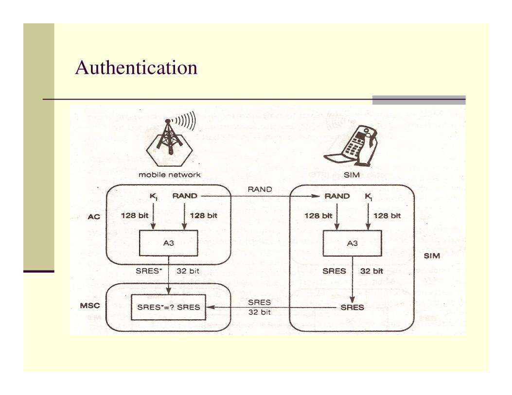
� It uses a challenge – response method
� The home system of the MS generates the 128 bit random
number (RAND). This number is sent to the MS
� The SIM within the MS responds with a signed response
(SRES)

Authentication
� The SRES generated by the MS is sent back to the home
system and compared with the SRES generated by the
AuC.
� If they are not identical, access request is rejected.
� If the SRES and RAND generated by the AuC are sent
from the HLR to the visited VLR in advance, then SRES
comparison is done at the VLR.
� The AuC generates the numbers for each IMSI and
forwards this information to the HLR

Authentication
� For authentication, the VLR sends this RAND value to the
SIM
� Both sides perform, the same function with the RAND and
Ki, called the A3 algorithm
� The MS sends back the SRES generated by the SIM� The MS sends back the SRES generated by the SIM
� Visited VLR compares both values
� If they are the same, the MS is accepted otherwise
rejected.
� The process of Authentication is illustrated in the next
slide.
Authentication
Encryption
� To ensure privacy, all messages containing user-related
information are encrypted over the air interface
� After the authentication process is complete, the MS and
BSS can start encrypting by applying the encryption key,
Kc c
� The encryption key is generated using the Ki and a
random value by applying the A8 algorithm.
� SIM in the MS and the network both calculate the same Kc
based on the random value
� MS and BTS can now encrypt and decrypt data using the
A5 algorithm and Kc

Encryption
� Like the A3 algorithm, A8 is specific to the home system.
After the home system has generated Kc, this is sent to
the visited system
� A5 is then used to encrypt and decrypt the data between
the MS and the visited system.
� The process of Encryption is illustrated in the following
slide.

Encryption


