CS65-Computer Networks Dept. of EEE Prepared by Dr.S.Muralidharan 1 IEEE 802 Project IEEE 802 Project IEEE 802 STANDARD In In 1985 1985, the the Computer Computer Society Society of of the the IEEE IEEE started started a project, project, called called Project Project 802 802, to to set set standards standards to to enable enable intercommunication intercommunication among among equipment equipment from from a variety variety of of manufacturers manufacturers. Project Project 802 802 is is a way way of of specifying specifying functions functions of of the the physical physical layer layer and and the the data data link link layer layer of of major major LAN LAN protocols protocols. LLC is non-architecture specific. ie. It is the same for all IEEE defined LANs. MAC sublayer is specific to the LAN product used.
Transcript
CS65-Computer Networks Dept. of EEE
Prepared by Dr.S.Muralidharan 1
IEEE 802 ProjectIEEE 802 Project
IEEE 802 STANDARDInIn 19851985,, thethe ComputerComputer SocietySociety ofof thethe IEEEIEEEstartedstarted aa project,project, calledcalled ProjectProject 802802,, toto setsetstandardsstandards toto enableenable intercommunicationintercommunication amongamongequipmentequipment fromfrom aa varietyvariety ofof manufacturersmanufacturers..ProjectProject 802802 isis aa wayway ofof specifyingspecifying functionsfunctions ofofthethe physicalphysical layerlayer andand thethe datadata linklink layerlayer ofof majormajorLANLAN protocolsprotocols..
LLC is non-architecture specific. ie. It is the same for all IEEE defined LANs.MAC sublayer is specific to the LAN product used.
CS65-Computer Networks Dept. of EEE
Prepared by Dr.S.Muralidharan 2
Logical Link Control (LLC) layer provides for the exchange of data between service access points(SAPs), which are multiplexed over a single physical connection to the LAN. The LLC provides for both a connectionless(datagram like) and connection oriented(virtual circuit like) service.Following are the IEEE protocols used in Data Link Layer– 802.1 - Internetworking– 802.2 - LLC– MAC Modules
The data unit in the LLC level is called “Protocol Data Unit (PDU)”. The PDU contains four fields – Destination service access point (DSAP)– Source service access point (SSAP)– Control field– Information field
The Service Access Point (SAP) is a conceptual location at which one OSI layer can request the services of another OSI layer.
Preamble:– 7 bytes with pattern 10101010– used to synchronize receiver, sender clock rates, and identify
beginning of a frame
Start of Frame Delimiter (SFD):– indicates start of frame - one byte with pattern 10101011 Destination Address: – 6-bytes globally unique address assigned by manufacturer. ie.
NIC address.– If the packet must cross from one LAN to another, the DA field
contains the physical address of router connecting that network. When the packet reaches the target network, the DA field contains the physical address of the destination device.
Source Address :– 6-bytes physical address of the last device to forward the packet.
That device can be the sending station or the most recent router to receive and forward the packet.
CS65-Computer Networks Dept. of EEE
Prepared by Dr.S.Muralidharan 4
Length/type of PDU :– 2byte information containing the length of PDU– If the length is fixed, then it is used to identify the type of
network level protocol using this PDU.802.2 Frame :– This field of 802.3 frame contains the entire 802.2 frame.– This PDU may vary between 46 to 1500 bytes – This frame is generated by upper LLC sub-layer.
Pad:– Zeroes used to ensure minimum frame length
CRC :– contains error detection information.
Media Sharing MEDIA SHARING
STATIC ALLOCATION• Using FDM
DYNAMIC ALLOCATION
SCHEDULING RANDOM ACCESS (Or)CONTENTION BASED
•ALOHA•CSMA•CSMA/CDCENTRALIZED
•PollingDISTRIBUTED•Token passing•Token ring
Operation of Ethernet– No central control– Stations are connected to a shared medium– Ethernet signals are transmitted serially, one bit at a
time, to every connected station– To send data,
• a station listens to the channel and if it is idle it transmits its data in the form of an Ethernet frame.
– Access to the medium is determined by the MAC• CSMA/CD protocol
CS65-Computer Networks Dept. of EEE
Prepared by Dr.S.Muralidharan 5
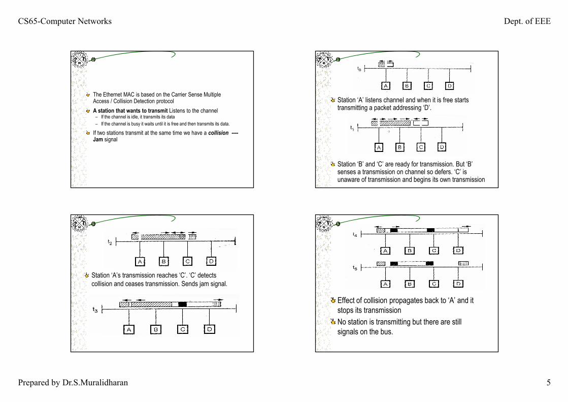
The Ethernet MAC is based on the Carrier Sense Multiple Access / Collision Detection protocolA station that wants to transmit Listens to the channel– If the channel is idle, it transmits its data– If the channel is busy it waits until it is free and then transmits its data.
If two stations transmit at the same time we have a collision ----Jam signal
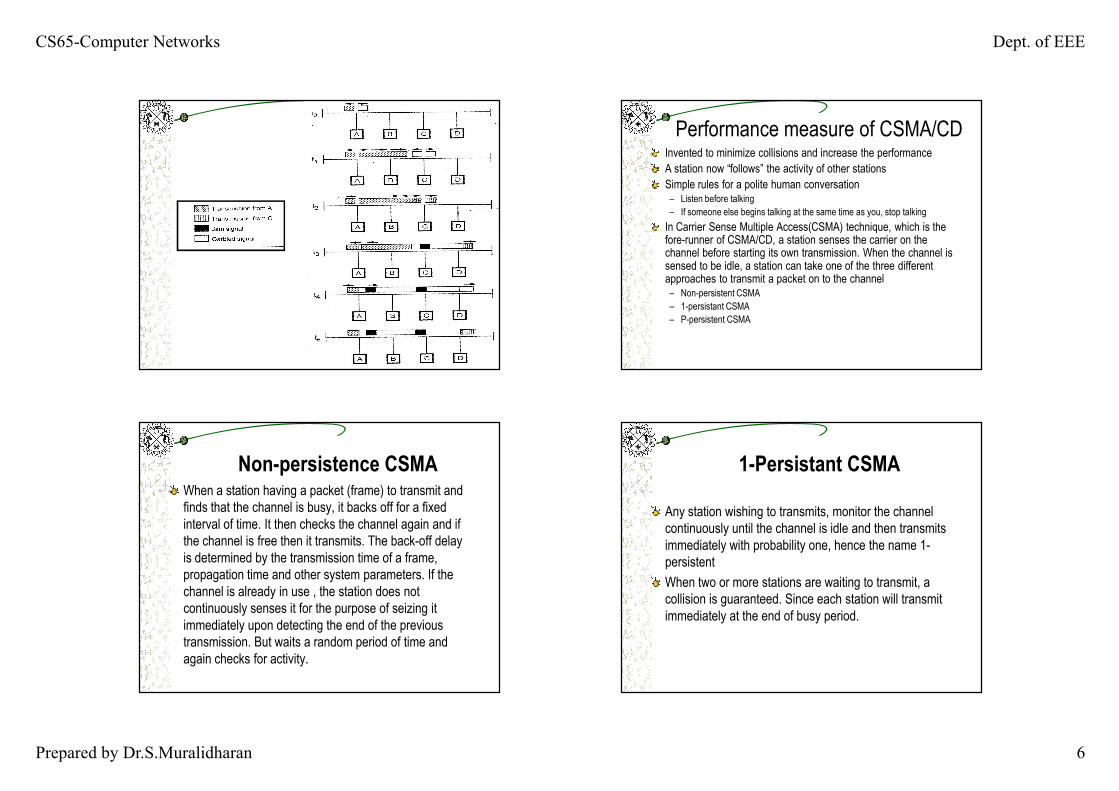
Station ‘A’ listens channel and when it is free starts transmitting a packet addressing ‘D’.
Station ‘B’ and ‘C’ are ready for transmission. But ‘B’ senses a transmission on channel so defers. ‘C’ is unaware of transmission and begins its own transmission
Station ‘A’s transmission reaches ‘C’. ‘C’ detects collision and ceases transmission. Sends jam signal.
Effect of collision propagates back to ‘A’ and it stops its transmissionNo station is transmitting but there are still signals on the bus.
CS65-Computer Networks Dept. of EEE
Prepared by Dr.S.Muralidharan 6
Performance measure of CSMA/CDInvented to minimize collisions and increase the performanceA station now “follows” the activity of other stationsSimple rules for a polite human conversation– Listen before talking– If someone else begins talking at the same time as you, stop talking
In Carrier Sense Multiple Access(CSMA) technique, which is the fore-runner of CSMA/CD, a station senses the carrier on the channel before starting its own transmission. When the channel is sensed to be idle, a station can take one of the three different approaches to transmit a packet on to the channel– Non-persistent CSMA– 1-persistant CSMA– P-persistent CSMA
Non-persistence CSMAWhen a station having a packet (frame) to transmit and finds that the channel is busy, it backs off for a fixed interval of time. It then checks the channel again and if the channel is free then it transmits. The back-off delay is determined by the transmission time of a frame, propagation time and other system parameters. If the channel is already in use , the station does not continuously senses it for the purpose of seizing it immediately upon detecting the end of the previous transmission. But waits a random period of time and again checks for activity.
1-Persistant CSMAAny station wishing to transmits, monitor the channel continuously until the channel is idle and then transmits immediately with probability one, hence the name 1-persistentWhen two or more stations are waiting to transmit, a collision is guaranteed. Since each station will transmit immediately at the end of busy period.
CS65-Computer Networks Dept. of EEE
Prepared by Dr.S.Muralidharan 7
Reduces the chance of collisions reduces the efficiency
� increases the chance for collisions� 1-persistant
� p-persistant� Decreases the chance for collisions� Improves efficiency
p - persistent CSMATo reduce the probability of collision in 1-persistant CSMA, not all the waiting stations are allowed to transmit immediately, after the channel is idle.Process includes :– Sense the channel.– IF the channel is idle, THEN with probability p transmit and with
probability (1-p) delay one time slot and repeat the algorithm..– IF the channel is busy, THEN delay one time slot and repeat the
algorithm. the time slot is usually set to the maximum propagation delay.as p decreases, stations wait longer to transmit but the number of collisions decreases.Consideration for the choice of p :
– (n x p) must be < 1 for stability, where n is maximum number of stations, i.e., p < 1/n