74
Lecture 7 • Demos: U-tube manomoter, Archimedes principle, const fluid height, venturi flowmeter.
| Date post: | 21-Dec-2015 |
| Category: |
Documents |
| View: | 228 times |
| Download: | 2 times |
Lecture 7
• Demos: U-tube manomoter, Archimedes principle, const fluid height, venturi flowmeter.
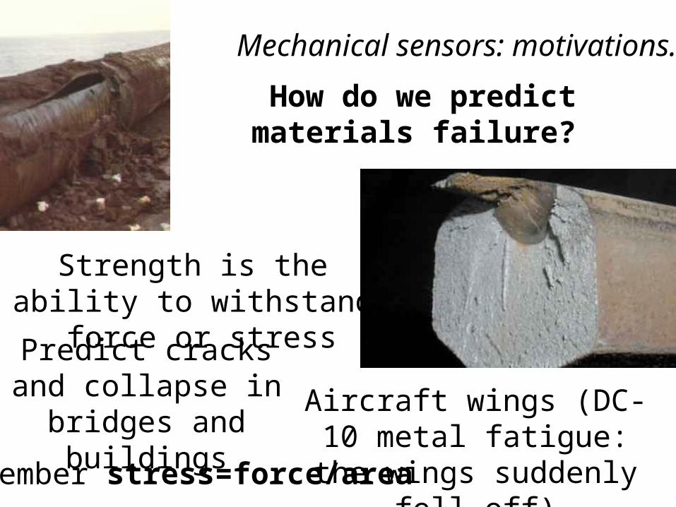
Mechanical sensors: motivations.
How do we predict materials failure?
Aircraft wings (DC-10 metal fatigue: the wings suddenly
fell off)
Predict cracks and collapse in bridges and
buildings
Strength is the ability to withstand force or stress
Remember stress=force/area
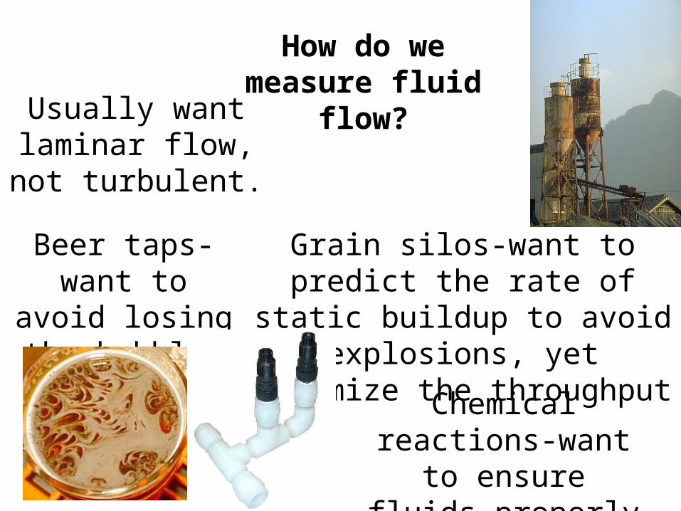
How do we measure fluid flow?
Beer taps-want to avoid losing the
bubbles
Grain silos-want to predict the rate of static buildup to avoid
explosions, yet maximize the throughput
Chemical reactions-want to ensure fluids
properly mixed
Usually want laminar flow, not
turbulent.

How do we measure hydrostatic pressure in fluids and liquids?
Blood/brain/spinal fluid pressure-how do we measure
non-invasively?
Hydraulic systems-bulldozer arms, car disk brakes/hydraulic lifts
How do divers know how much air they have left in
their tanks?
Pressure sensors:
How do we tell when someone is walking down a corridor?
How can we weigh trucks as they pass over a road?
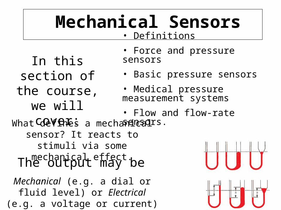
Mechanical Sensors
What defines a mechanical sensor? It reacts to stimuli via some mechanical
effect.
The output may be
Mechanical (e.g. a dial or fluid level) or Electrical (e.g. a voltage or current)
• Definitions
• Force and pressure sensors
• Basic pressure sensors
• Medical pressure measurement systems
• Flow and flow-rate sensors.
In this section of the course, we will
cover:
Force and Pressure SensorsHow do we measure an unknown force?
Acceleration Method
Apply force to known mass, measure acceleration.
Example: Force on Pendulum, apply force measure deflection.
Force and Pressure Sensors
Gravity balance method.
Compare unknown force with action of gravitational force.
Example: Balance scale. (zero-balance method)
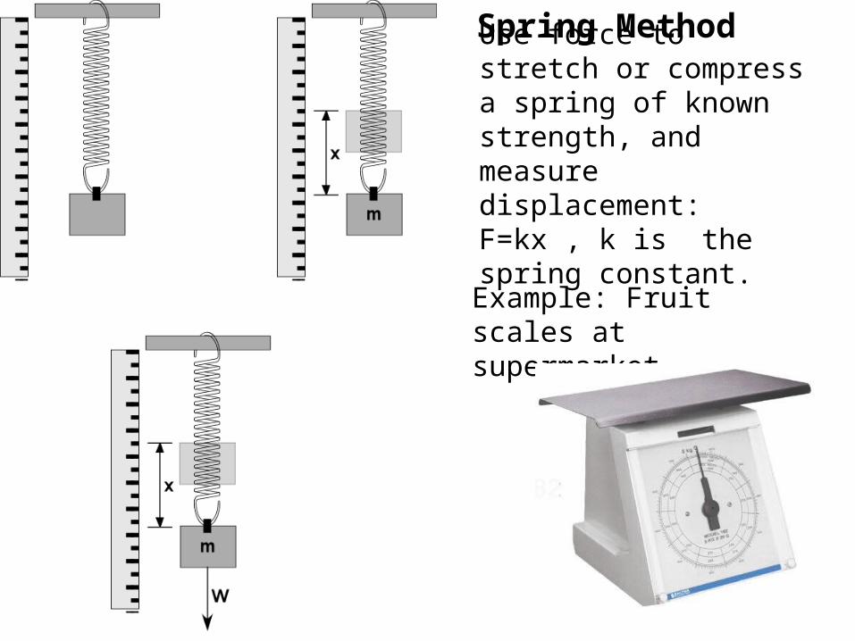
Spring Method
Use force to stretch or compress a spring of known strength, and measure displacement: F=kx , k is the spring constant.
Example: Fruit scales at supermarket
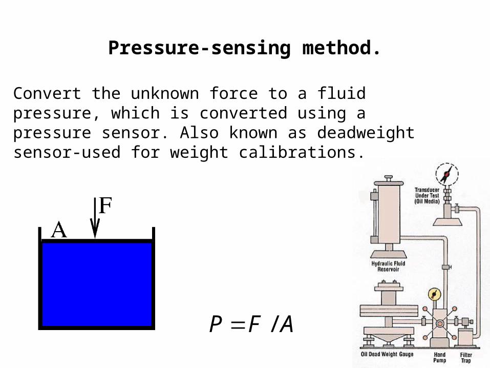
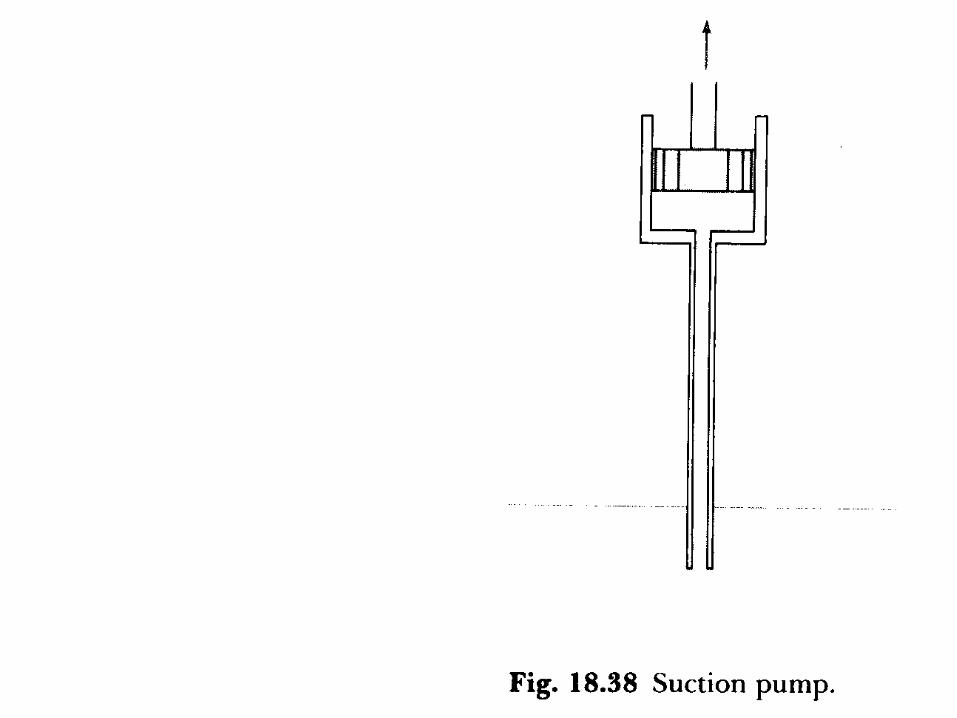
Pressure-sensing method.
Convert the unknown force to a fluid pressure, which is converted using a pressure sensor. Also known as deadweight sensor-used for weight calibrations.
AFP /
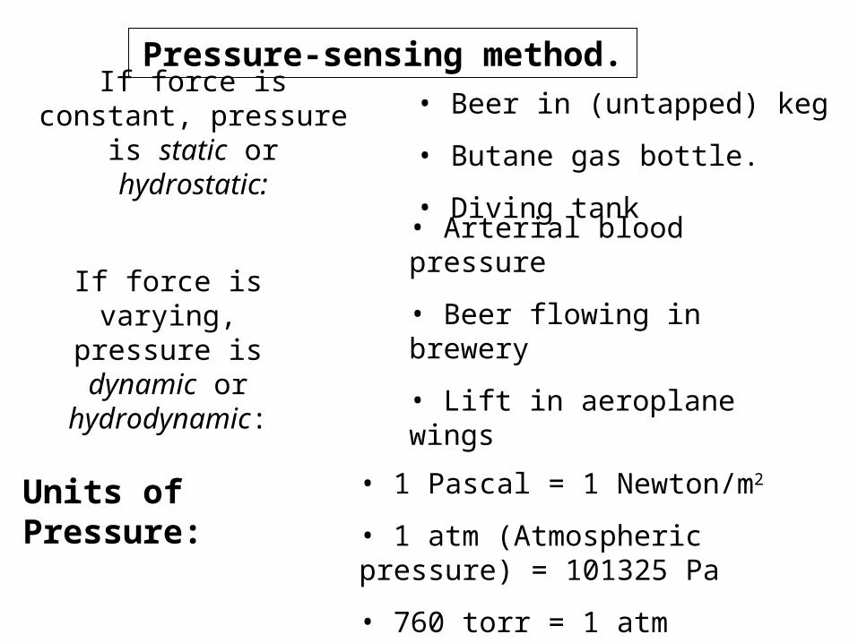
If force is constant, pressure is static or hydrostatic:
• Beer in (untapped) keg
• Butane gas bottle.
• Diving tank
If force is varying, pressure is dynamic or
hydrodynamic:
• Arterial blood pressure
• Beer flowing in brewery
• Lift in aeroplane wings
Units of Pressure: • 1 Pascal = 1 Newton/m2
• 1 atm (Atmospheric pressure) = 101325 Pa
• 760 torr = 1 atm
Pressure-sensing method.
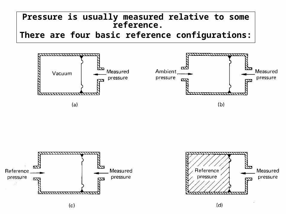
Pressure is usually measured relative to some reference. There are four basic reference configurations:
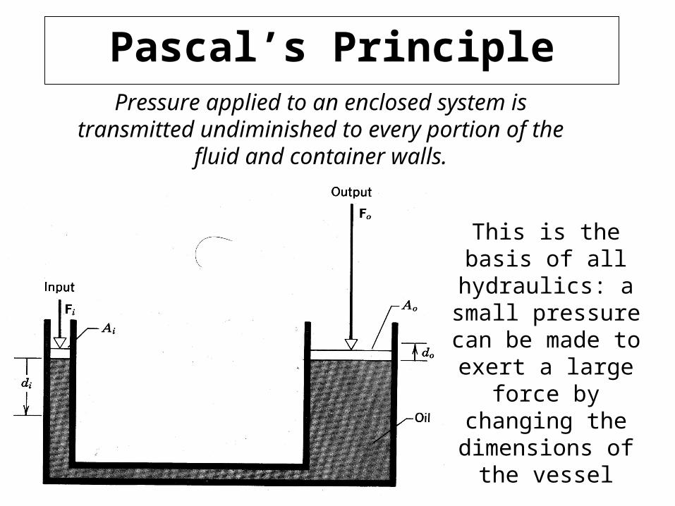
Pascal’s PrinciplePressure applied to an enclosed system is transmitted
undiminished to every portion of the fluid and container walls.
This is the basis of all hydraulics: a small
pressure can be made to exert a large force
by changing the dimensions of the
vessel
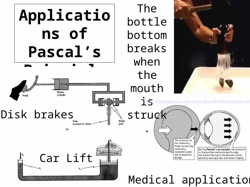
Applications of Pascal’s Principle
Disk brakes
Car Lift
Medical applications
The bottle
bottom breaks
when the mouth is struck.
http://hyperphysics.phy-astr.gsu.edu/hbase/pasc4.html#c1

Notes on Pascal’s principle
Pascal’s principle neglects the effects of gravity-need to add the contribution ρgh where ρ is the density, g the acceleration due to gravity, and h the height of the fluid.
Also, only true in hydrodynamic systems if change is quasi-static.Quasi-static means that after a small change is made, turbulence is allowed to die down then measurement is made.Examples are hydrodynamic systems where flow is non-turbulent and the pipe orifice is small compared with its length.
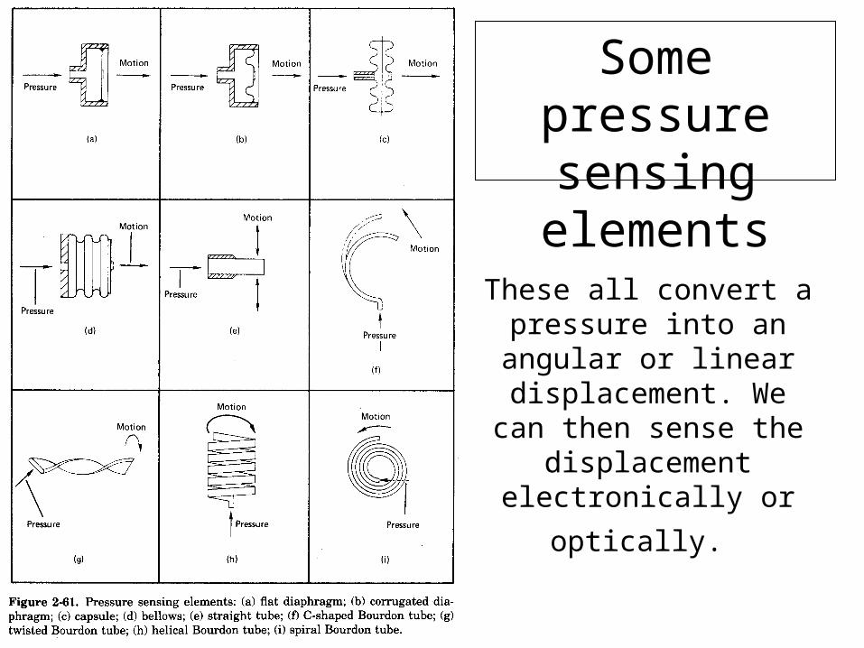
From H. Norton, ‘Sensor and analyzer handbook’
These all convert a pressure into an angular or linear
displacement. We can then sense the displacement
electronically or optically.
Some pressure sensing elements

Bourdon tube sensor
Bourdon tube pressure sensor: curved or twisted tube, sealed at one end.
As pressure inside changes, tube uncurls;
this displacement can be transduced using a
variable sliding resistior, or linked directly to a dial
readout.
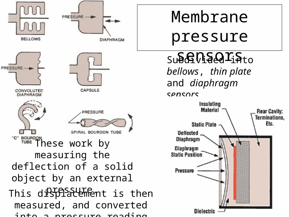
Membrane pressure sensors
Subdivided into bellows, thin plate and diaphragm sensors.
These work by measuring the deflection of a solid object by
an external pressure.
This displacement is then measured, and converted into a pressure reading
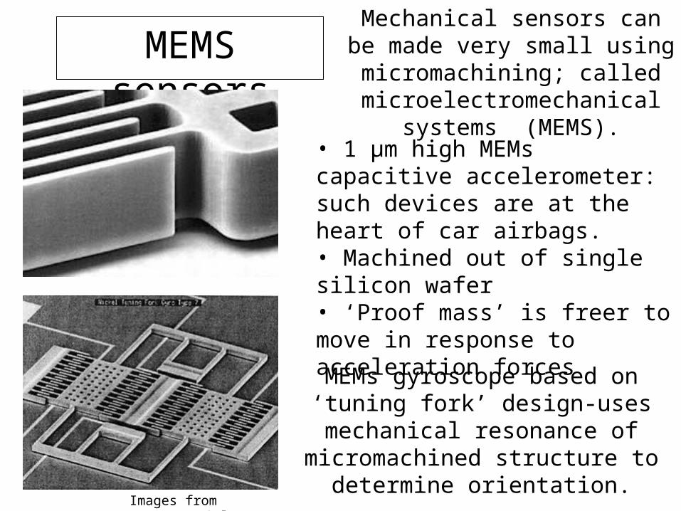
MEMS sensors
• 1 μm high MEMs capacitive accelerometer: such devices are at the heart of car airbags.• Machined out of single silicon wafer• ‘Proof mass’ is freer to move in response to acceleration forces
Images from www.sensorsmag.com/articles/0203/14/
MEMs gyroscope based on ‘tuning fork’ design-uses mechanical
resonance of micromachined structure to determine orientation.
Mechanical sensors can be made very small using micromachining;
called microelectromechanical systems (MEMS).
Medical pressure measurement.
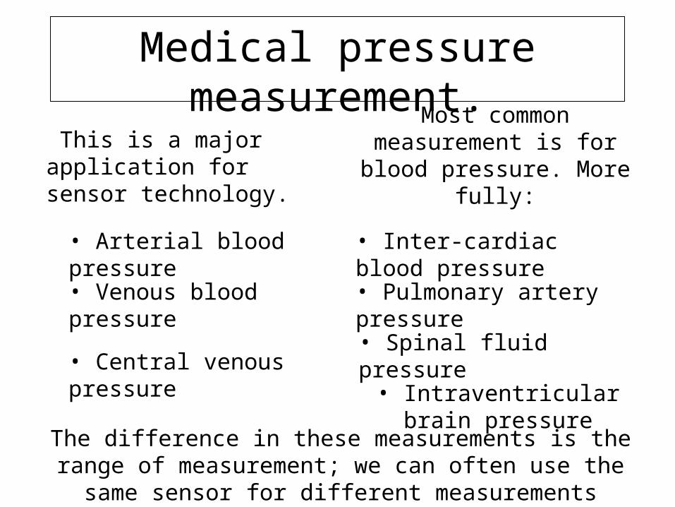
This is a major application for sensor technology.
Most common measurement is for blood pressure. More fully:
• Inter-cardiac blood pressure
• Arterial blood pressure
• Spinal fluid pressure• Central venous pressure
• Pulmonary artery pressure• Venous blood pressure
• Intraventricular brain pressure
The difference in these measurements is the range of measurement; we can often use the same sensor for different measurements

Medical students are often told there is an “Ohm’s law for blood”
P=F.R , Where:
• P is pressure difference in torr.
• F is flow rate in millilitres/second.
• R is blood vessel resistance in “periphial resistance units” (PRU) where 1 PRU allows a flow of 1 ml/s under 1 torr pressure.
This is misleading: in fact, blood vessels change diameter from systemic adjustments and from pulsatile pressure wave.
• minimally invasive
• sterile
• electrically insulated
Medical sensors should be:
Medical pressure sensors
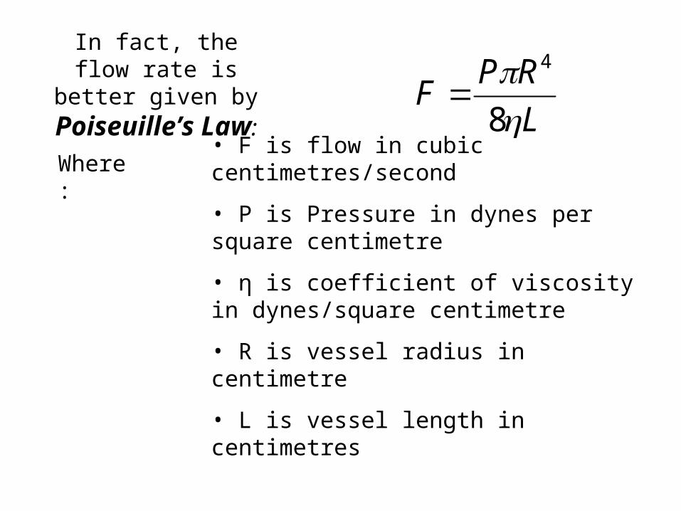
In fact, the flow rate is better given by
Poiseuille’s Law: L
RPF
8
4
Where:• F is flow in cubic centimetres/second
• P is Pressure in dynes per square centimetre
• η is coefficient of viscosity in dynes/square centimetre
• R is vessel radius in centimetre
• L is vessel length in centimetres
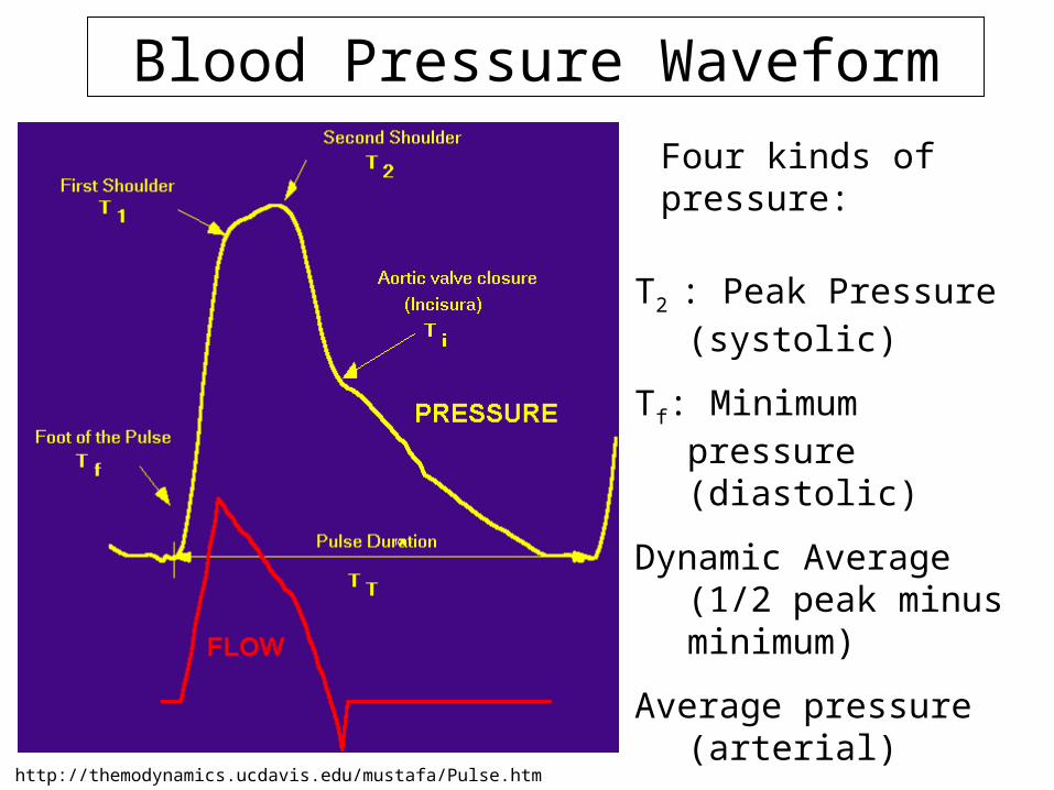
Blood Pressure Waveform
Four kinds of pressure:
T2 : Peak Pressure (systolic)
Tf: Minimum pressure (diastolic)
Dynamic Average (1/2 peak minus minimum)
Average pressure (arterial)
http://themodynamics.ucdavis.edu/mustafa/Pulse.htm
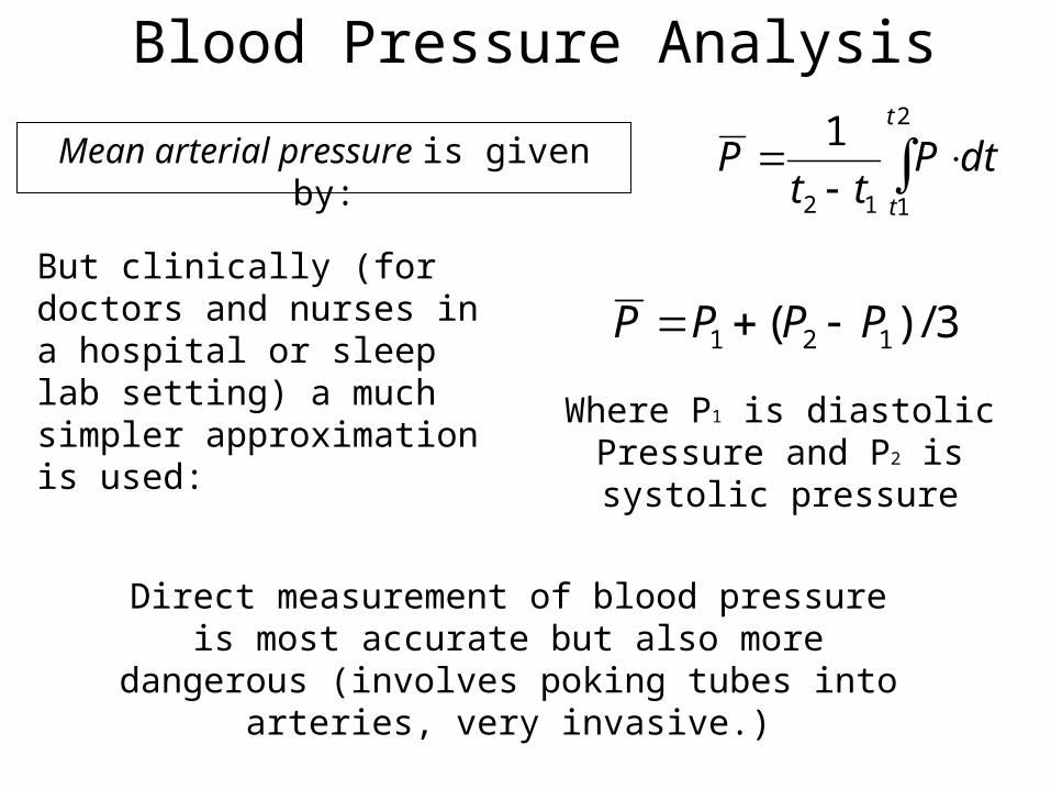
Mean arterial pressure is given by:
2
112
1 t
t
dtPtt
P
But clinically (for doctors and nurses in a hospital or sleep lab setting) a much simpler approximation is used:
3/)( 121 PPPP
Where P1 is diastolic Pressure and P2 is systolic pressure
Direct measurement of blood pressure is most accurate but also more dangerous (involves poking tubes into
arteries, very invasive.)
Blood Pressure Analysis
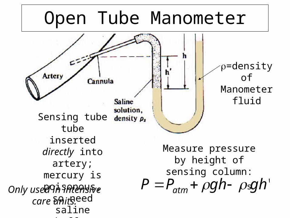
Open Tube Manometer
Sensing tube tube inserted directly
into artery; mercury is
poisonous, so need saline buffer
Measure pressure by height of sensing column:
Only used in intensive care units.
'sghghPP atm
=density of Manometer fluid
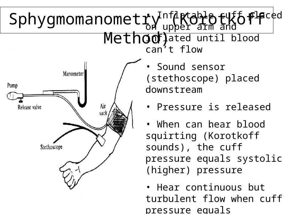
Sphygmomanometry (Korotkoff Method)• Inflatable cuff placed on upper arm and inflated until blood can’t flow
• Sound sensor (stethoscope) placed downstream
• Pressure is released
• When can hear blood squirting (Korotkoff sounds), the cuff pressure equals systolic (higher) pressure
• Hear continuous but turbulent flow when cuff pressure equals diastolic pressure
.
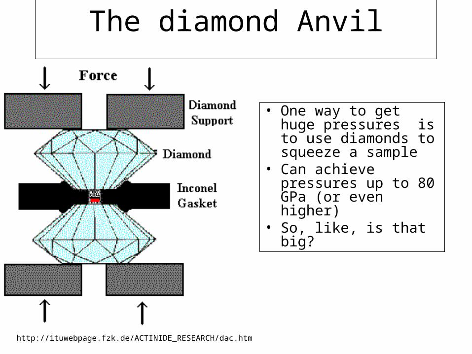
The diamond Anvil
• One way to get huge pressures is to use diamonds to squeeze a sample
• Can achieve pressures up to 80 GPa (or even higher)
• So, like, is that big?
http://ituwebpage.fzk.de/ACTINIDE_RESEARCH/dac.htm
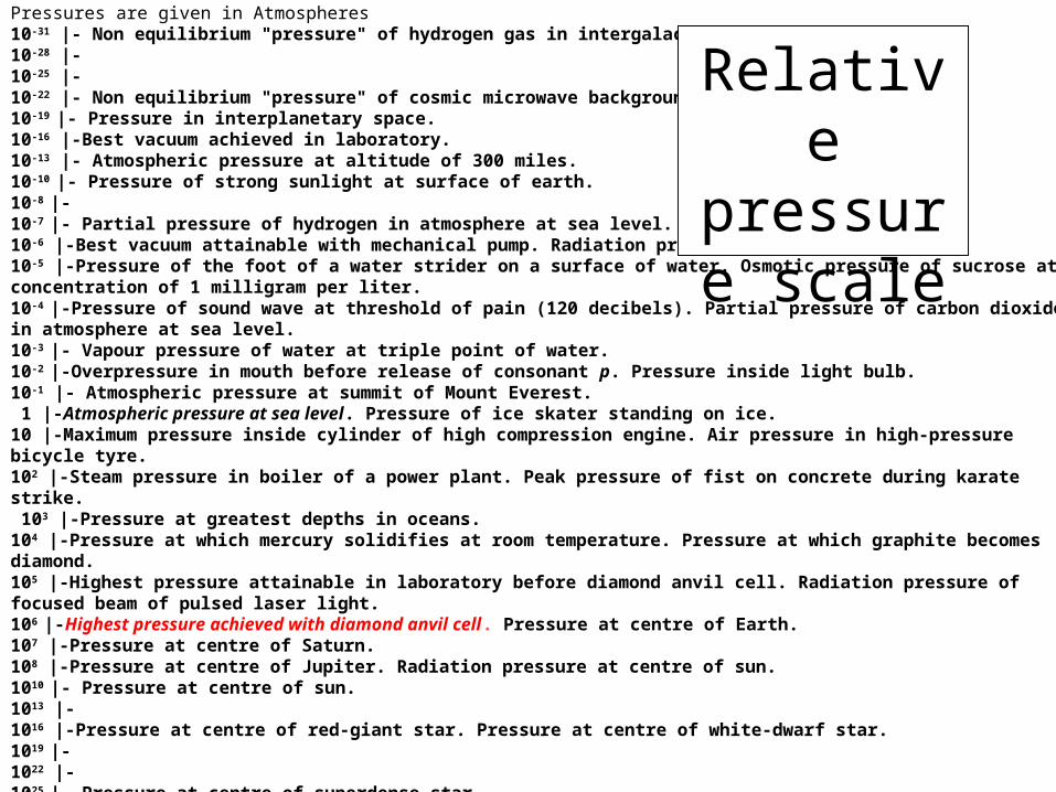
Pressures are given in Atmospheres10-31 |- Non equilibrium "pressure" of hydrogen gas in intergalactic space. 10-28 |-10-25 |-10-22 |- Non equilibrium "pressure" of cosmic microwave background radiation. 10-19 |- Pressure in interplanetary space. 10-16 |-Best vacuum achieved in laboratory. 10-13 |- Atmospheric pressure at altitude of 300 miles. 10-10 |- Pressure of strong sunlight at surface of earth. 10-8 |- 10-7 |- Partial pressure of hydrogen in atmosphere at sea level. 10-6 |-Best vacuum attainable with mechanical pump. Radiation pressure at surface of sun. 10-5 |-Pressure of the foot of a water strider on a surface of water. Osmotic pressure of sucrose at concentration of 1 milligram per liter. 10-4 |-Pressure of sound wave at threshold of pain (120 decibels). Partial pressure of carbon dioxide in atmosphere at sea level. 10-3 |- Vapour pressure of water at triple point of water. 10-2 |-Overpressure in mouth before release of consonant p. Pressure inside light bulb. 10-1 |- Atmospheric pressure at summit of Mount Everest. 1 |-Atmospheric pressure at sea level. Pressure of ice skater standing on ice. 10 |-Maximum pressure inside cylinder of high compression engine. Air pressure in high-pressure bicycle tyre. 102 |-Steam pressure in boiler of a power plant. Peak pressure of fist on concrete during karate strike. 103 |-Pressure at greatest depths in oceans. 104 |-Pressure at which mercury solidifies at room temperature. Pressure at which graphite becomes diamond. 105 |-Highest pressure attainable in laboratory before diamond anvil cell. Radiation pressure of focused beam of pulsed laser light. 106 |-Highest pressure achieved with diamond anvil cell. Pressure at centre of Earth. 107 |-Pressure at centre of Saturn. 108 |-Pressure at centre of Jupiter. Radiation pressure at centre of sun. 1010 |- Pressure at centre of sun. 1013 |- 1016 |-Pressure at centre of red-giant star. Pressure at centre of white-dwarf star. 1019 |- 1022 |- 1025 |- Pressure at centre of superdense star. 1028 |- Pressure at centre of neutron star.
Relative pressure
scale
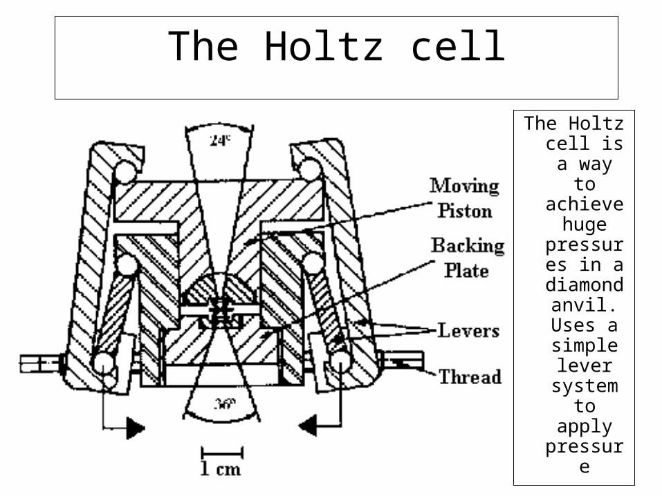
The Holtz cell
The Holtz cell is a way to achieve
huge pressures
in a diamond
anvil. Uses a simple lever
system to apply pressure

The diamond Anvil
A photo of a working
diamond anvil at the institute for transuranic
elements, in Europe
Lecture 8
• Demos-Bernoulli’s law.
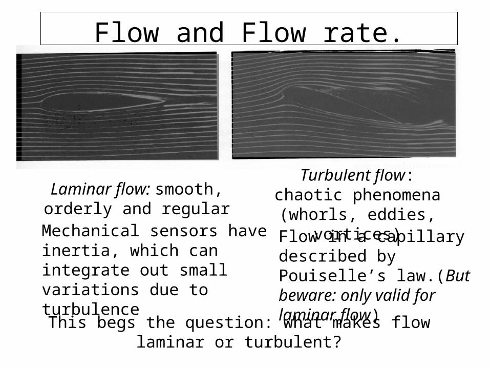
Flow and Flow rate.
Laminar flow: smooth, orderly and regular
Turbulent flow: chaotic phenomena (whorls,
eddies, vortices)
Mechanical sensors have inertia, which can integrate out small variations due to turbulence
Flow in a capillary described by Pouiselle’s law.(But beware: only valid for laminar flow)
This begs the question: what makes flow laminar or turbulent?
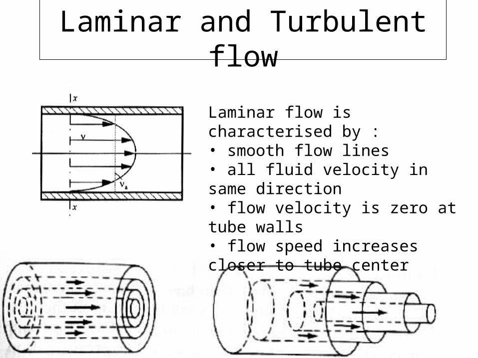
Laminar and Turbulent flow
Laminar flow is characterised by :• smooth flow lines• all fluid velocity in same direction• flow velocity is zero at tube walls• flow speed increases closer to tube center
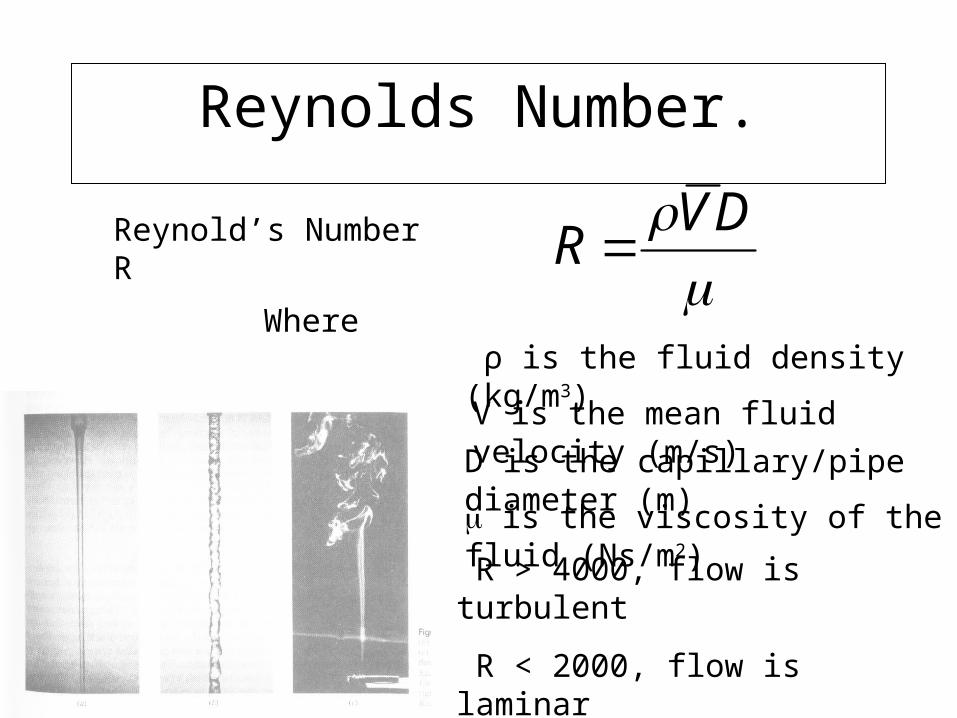
Reynolds Number.
DV
R Reynold’s Number R
Where
ρ is the fluid density (kg/m3)
V is the mean fluid velocity (m/s)
D is the capillary/pipe diameter (m)
is the viscosity of the fluid (Ns/m2)
R > 4000, flow is turbulent
R < 2000, flow is laminar

Flow Sensors
Many sensors measure flow rate.
Mass flow rate: mass transferred per unit time (kg/s)
Volumetric flow rate: volume of material per unit time (m3/s)
In gas systems, mass and volume rates are expressed in volume flow.
Mass flow referenced to STP (standard temperature and pressure) and converted to equivalent volume flow (eg sccm = standard cubic centimetres per minute)
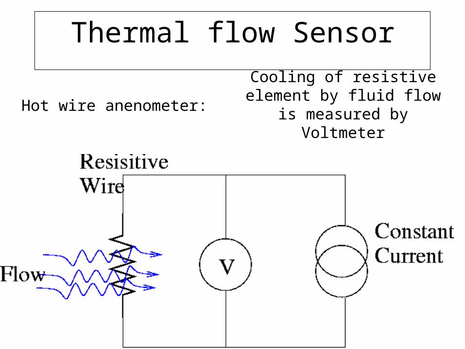
Thermal flow Sensor
Hot wire anenometer:Cooling of resistive element by
fluid flow is measured by Voltmeter
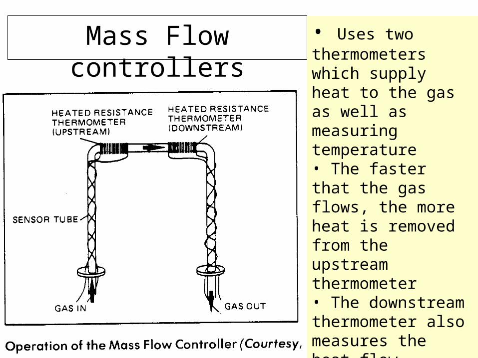
Mass Flow controllers • Uses two thermometers which supply heat to the gas as well as measuring temperature• The faster that the gas flows, the more heat is removed from the upstream thermometer• The downstream thermometer also measures the heat flow, increasing accuracy• No contact between sensors and gases (no contamination)
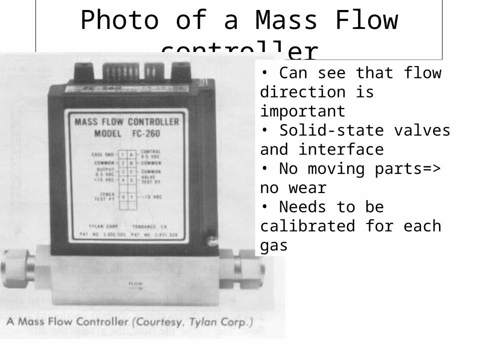
Photo of a Mass Flow controller
• Can see that flow direction is important• Solid-state valves and interface • No moving parts=> no wear• Needs to be calibrated for each gas
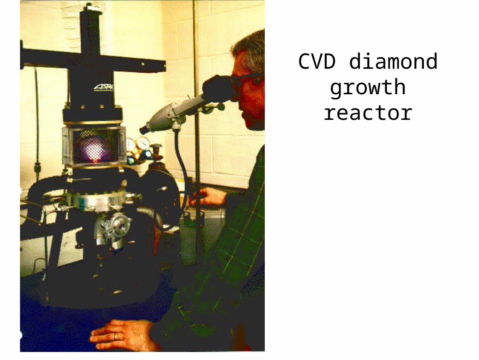
CVD diamond growth reactor
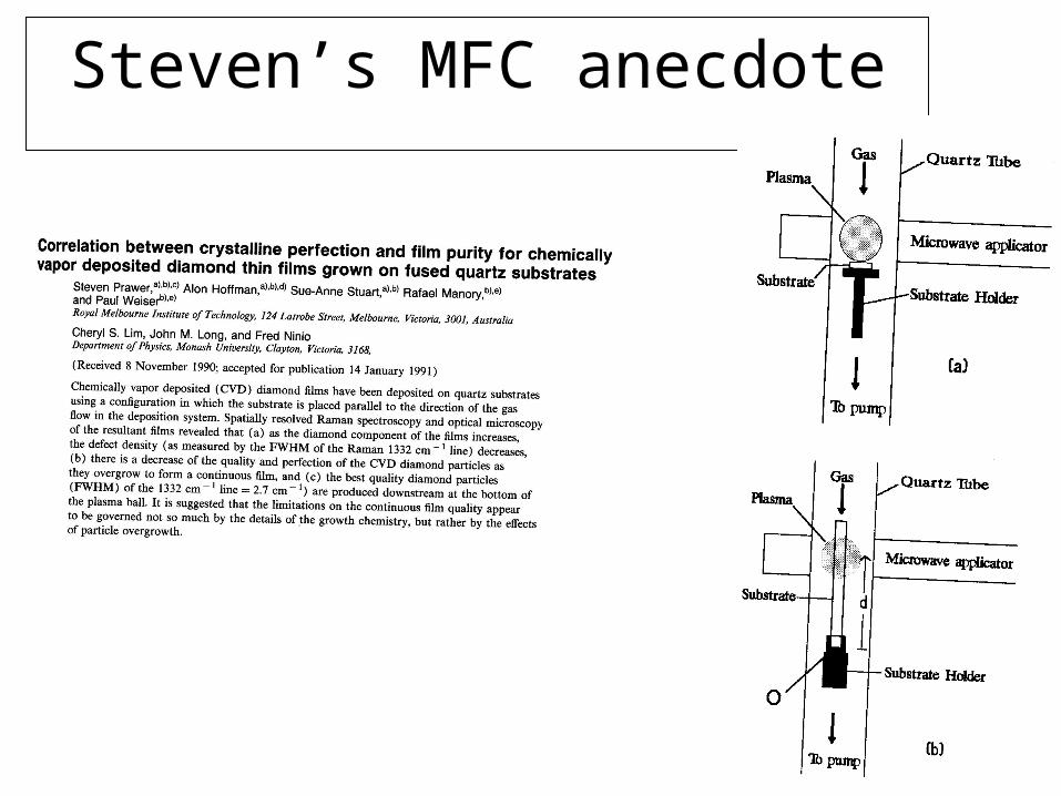
Steven’s MFC anecdote
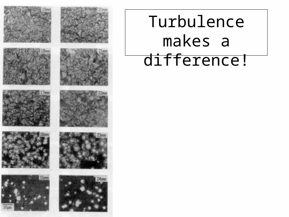
Turbulence makes a difference!
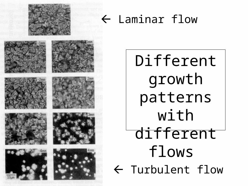
Different growth
patterns with different flows
Turbulent flow
Laminar flow
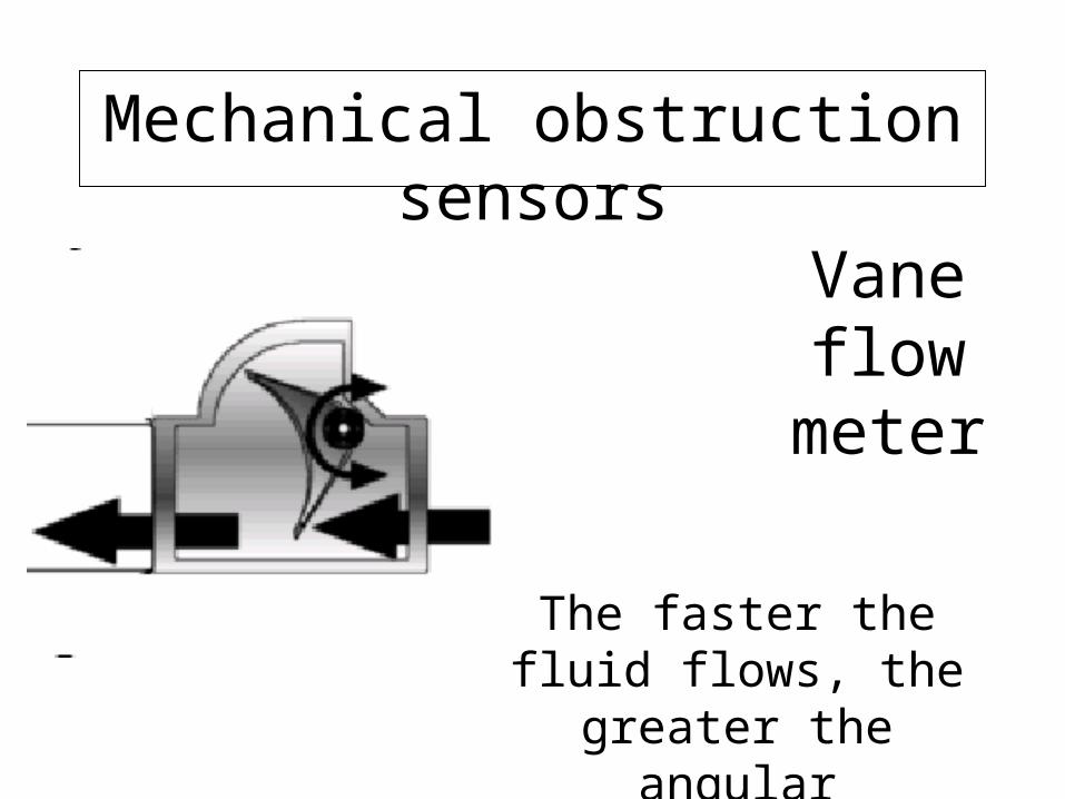
Mechanical obstruction sensors
Vane flow meter
The faster the fluid flows, the greater the angular
displacement.
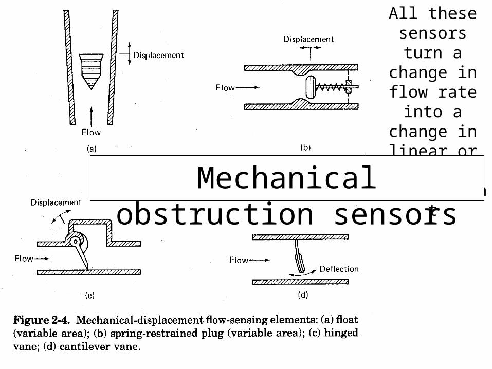
All these sensors turn a change in flow
rate into a change in linear
or angular displacement
Mechanical obstruction sensors
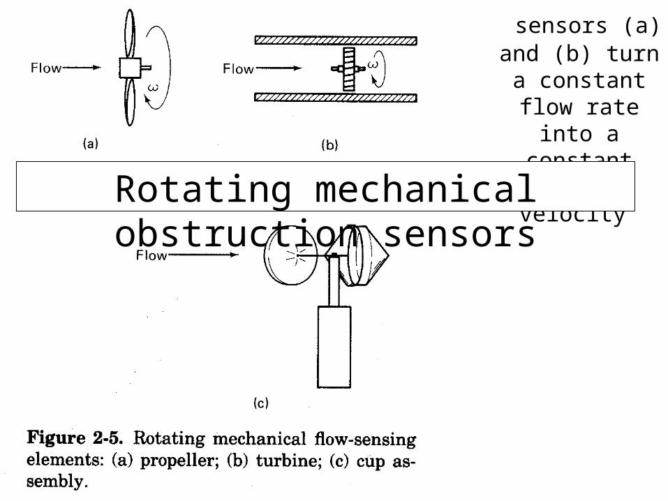
sensors (a) and (b) turn a constant
flow rate into a constant angular
velocity
Rotating mechanical obstruction sensors
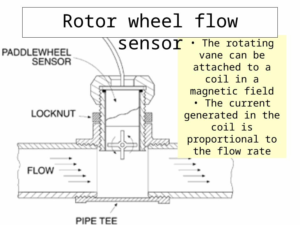
• The rotating vane can be attached to a coil in a
magnetic field• The current generated
in the coil is proportional to the flow rate
Rotor wheel flow sensor
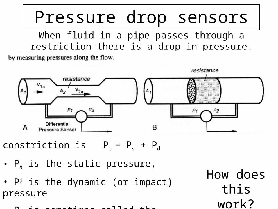
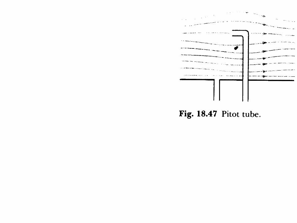
Pressure drop sensorsWhen fluid in a pipe passes through a restriction there is a drop
in pressure.
Total pressure, Pt, after the constriction is Pt = Ps + Pd
• Ps is the static pressure,
• Pd is the dynamic (or impact) pressure
• Pt is sometimes called the stagnation pressure
How does this work?
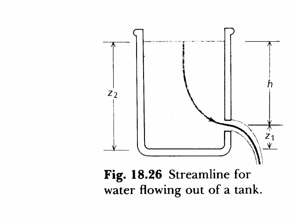
Bernoulli’s Equation
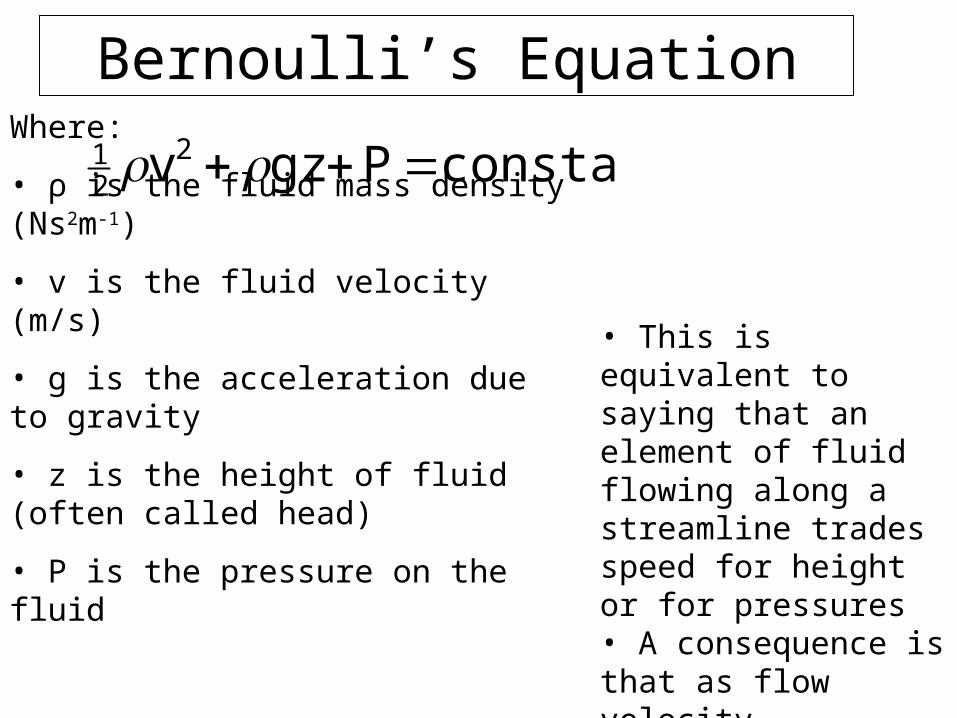
constantPgzv221
Where:
• ρ is the fluid mass density (Ns2m-1)
• v is the fluid velocity (m/s)
• g is the acceleration due to gravity
• z is the height of fluid (often called head)
• P is the pressure on the fluid
• This is equivalent to saying that an element of fluid flowing along a streamline trades speed for height or for pressures• A consequence is that as flow velocity increases, the pressure on the vessel walls decreases
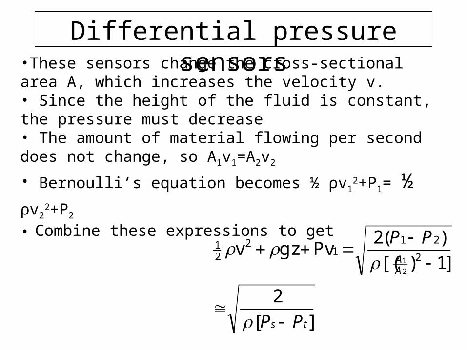
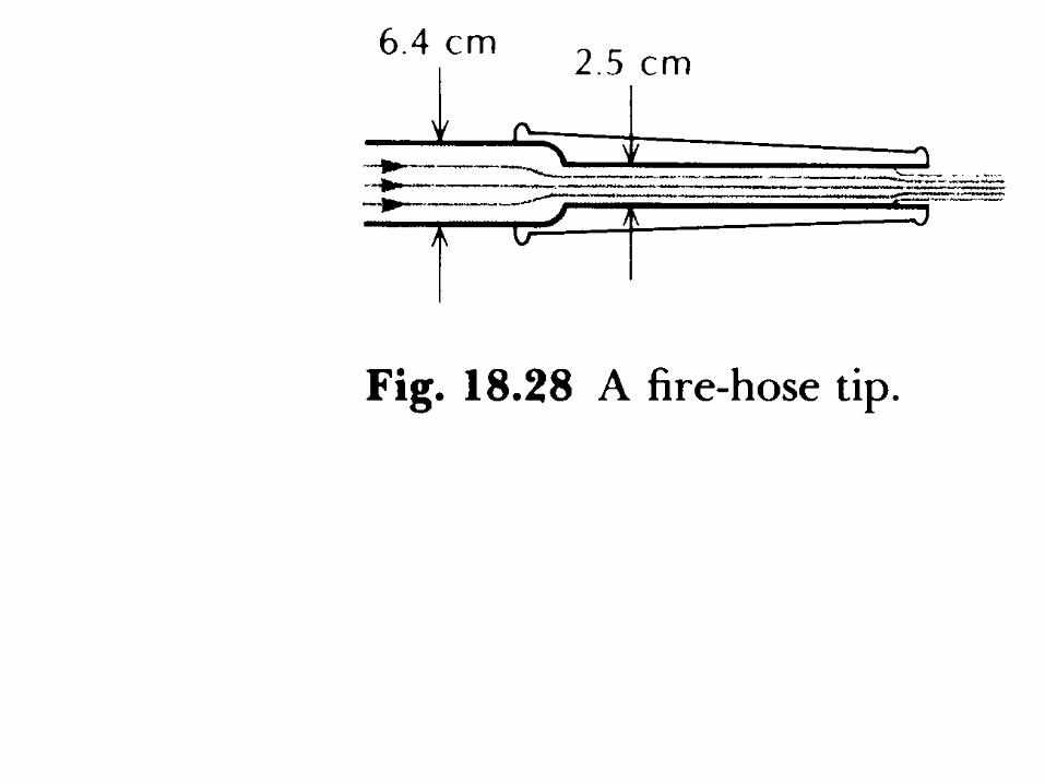
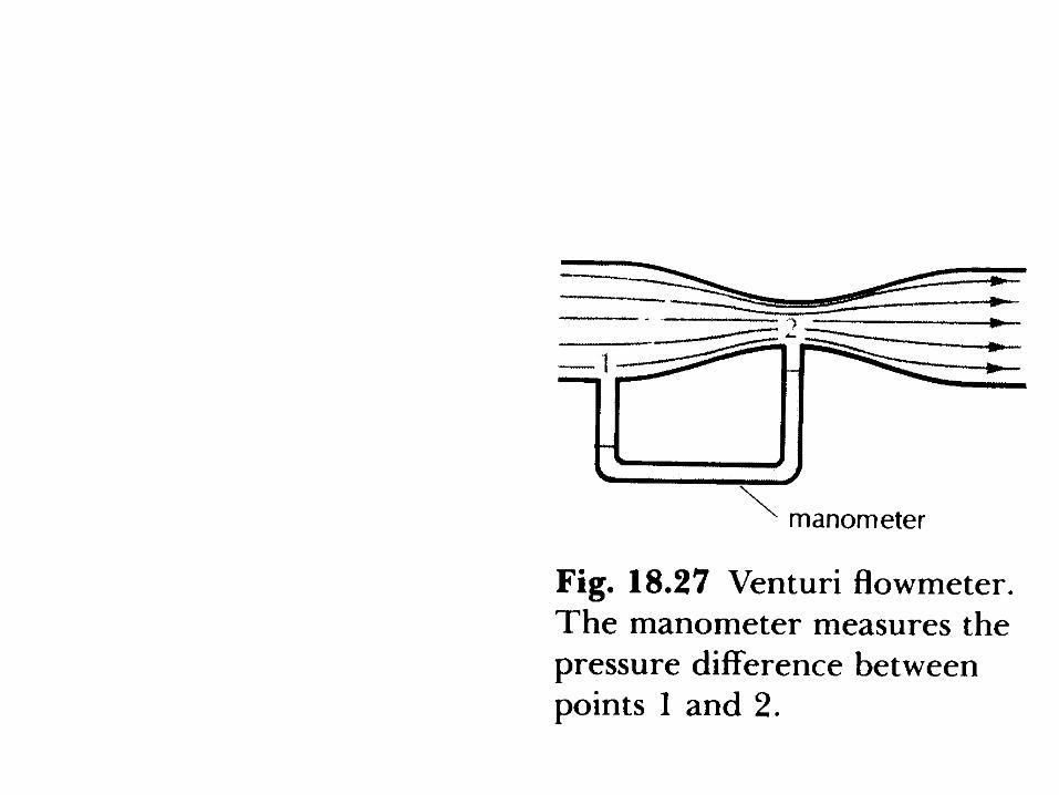
Differential pressure sensors•These sensors change the cross-sectional area A, which increases the velocity v.• Since the height of the fluid is constant, the pressure must decrease• The amount of material flowing per second does not change, so A1v1=A2v2
• Bernoulli’s equation becomes ½ ρv12+P1= ½ ρv2
2+P2 • Combine these expressions to get
][
2
]1)[(
)(2Pvgzv
2
211
221
2
1
ts
AA
PP
PP
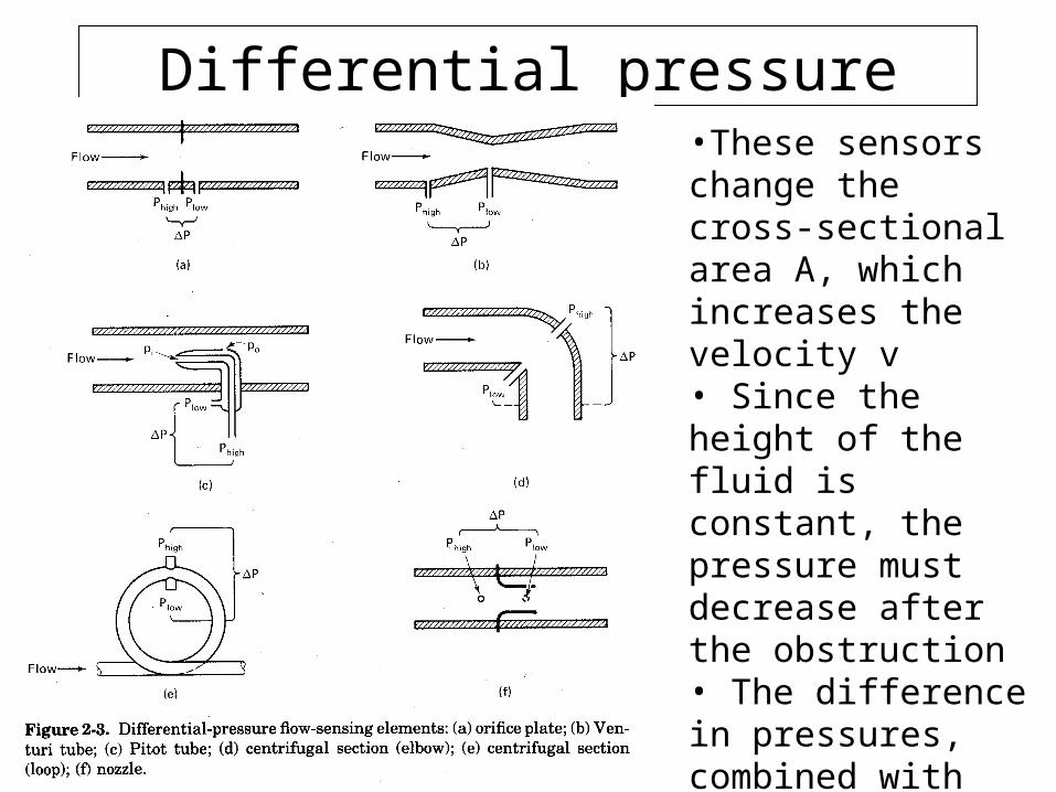
Differential pressure sensors•These sensors change the cross-sectional area A, which increases the velocity v• Since the height of the fluid is constant, the pressure must decrease after the obstruction• The difference in pressures, combined with the cross-sectional area, tells us the velocity before the obstruction

Wire mesh flow sensor
www.fz-rossendorf.de/FWS/publikat/JB98/jb05.pdf
• Used to measure bubble propagation in gases• Uses grid of wires to measure electrical conductivity at wire crossing points
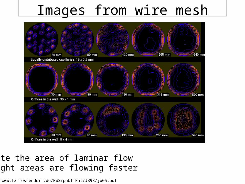
Images from wire mesh sensor
www.fz-rossendorf.de/FWS/publikat/JB98/jb05.pdf
• Note the area of laminar flow• Light areas are flowing faster
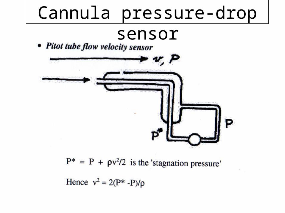
Cannula pressure-drop sensor
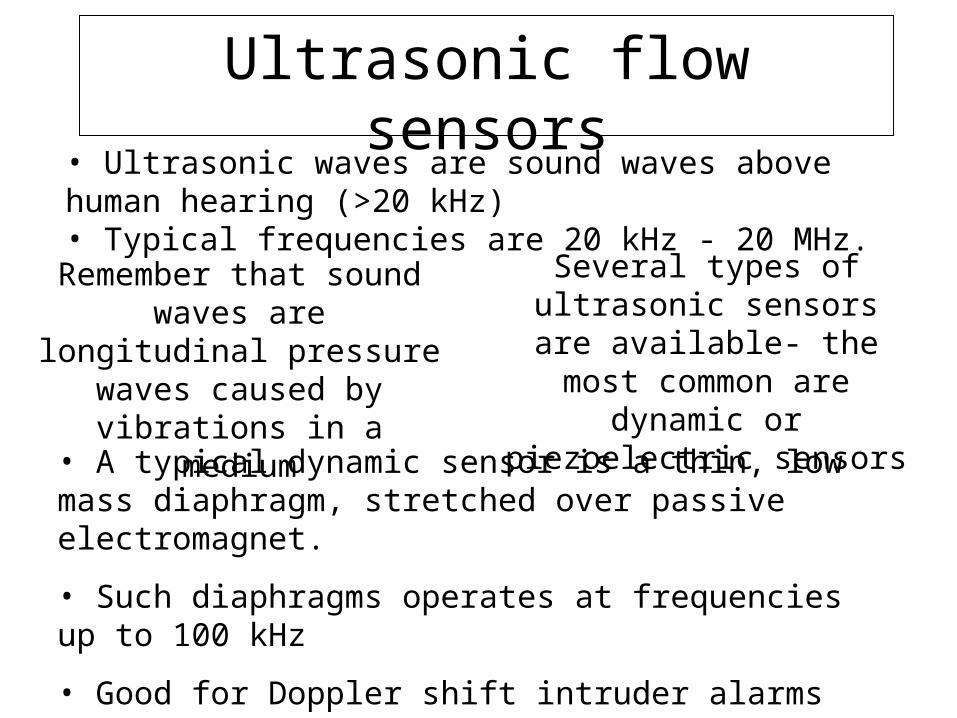
Ultrasonic flow sensors
• Ultrasonic waves are sound waves above human hearing (>20 kHz) • Typical frequencies are 20 kHz - 20 MHz.
Several types of ultrasonic sensors are available- the most
common are dynamic or piezoelectric sensors
• A typical dynamic sensor is a thin, low mass diaphragm, stretched over passive electromagnet.
• Such diaphragms operates at frequencies up to 100 kHz
• Good for Doppler shift intruder alarms (demo)
Remember that sound waves are longitudinal pressure waves
caused by vibrations in a medium
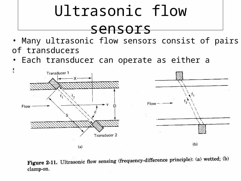
Ultrasonic flow sensors
• Many ultrasonic flow sensors consist of pairs of transducers• Each transducer can operate as either a source or a detector of sound waves
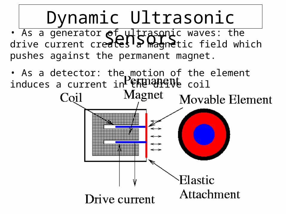
Dynamic Ultrasonic Sensors• As a generator of ultrasonic waves: the drive current creates a magnetic field which pushes against the permanent magnet.
• As a detector: the motion of the element induces a current in the drive coil
Piezoelectric ultrasonic transducers• We have encountered piezoelectrics in the context of force sensors
• An extension of this is the use of piezos to convert the compressions and rarefactions of a sound wave into an electrical signal
• Deforms a crystalline structure under potential stimulation
Operated at resonant frequency (quartz crystal reference)
Used in computers and wrist watches as a time reference.
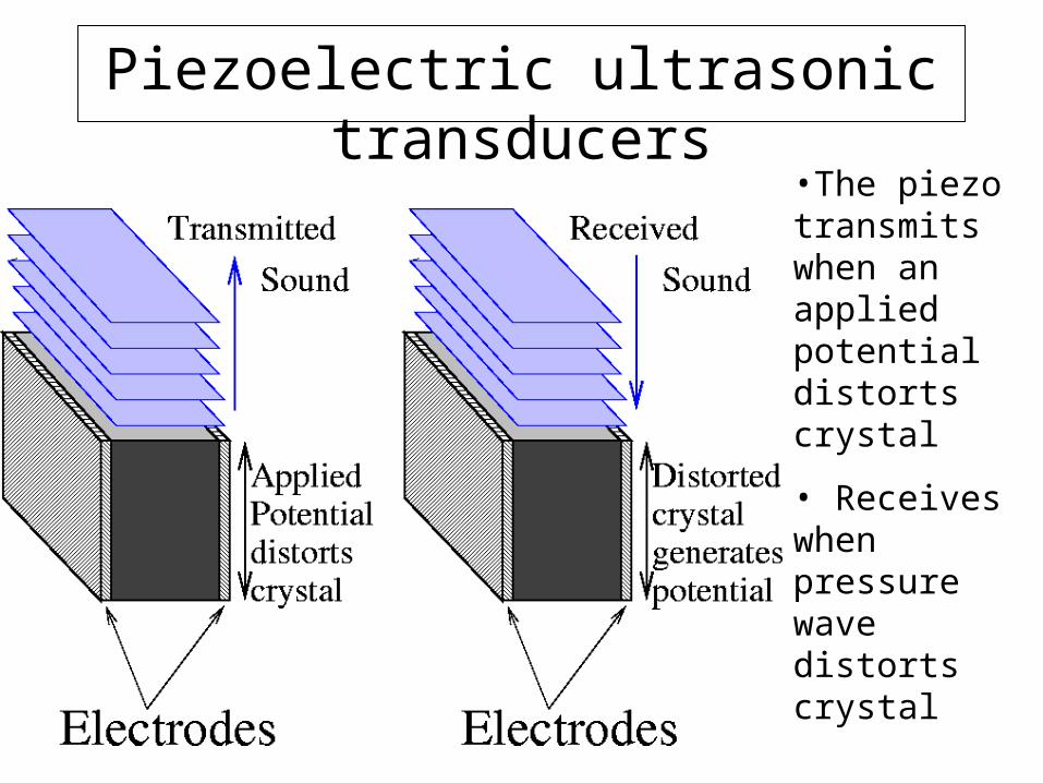
Piezoelectric ultrasonic transducers
•The piezo transmits when an applied potential distorts crystal
• Receives when pressure wave distorts crystal

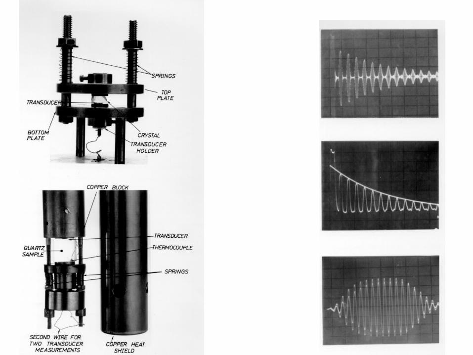
Measuring the speed of sound in a
crystal using ultrasound
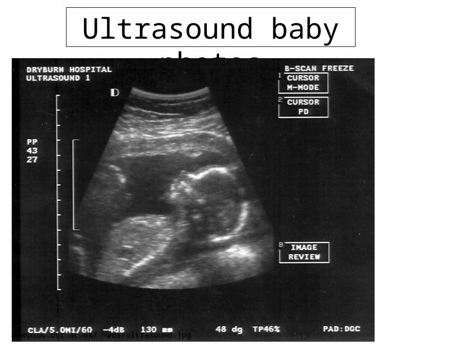
Ultrasound baby photos
compsoc.dur.ac.uk/ ~ads/ultrasound.jpg
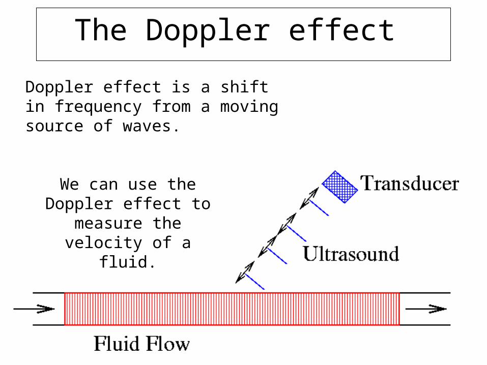
The Doppler effect
We can use the Doppler effect to measure the velocity of a fluid.
Doppler effect is a shift in frequency from a moving source of waves.
sc
ff
)cos(v2
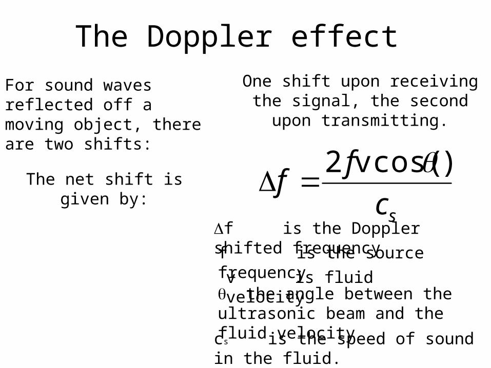
For sound waves reflected off a moving object, there are two shifts:
One shift upon receiving the signal, the second upon transmitting.
The net shift is given by:
f is the Doppler shifted frequency
f is the source frequency
v is fluid velocity the angle between the ultrasonic beam and the fluid velocity
cs is the speed of sound in the fluid.
The Doppler effect
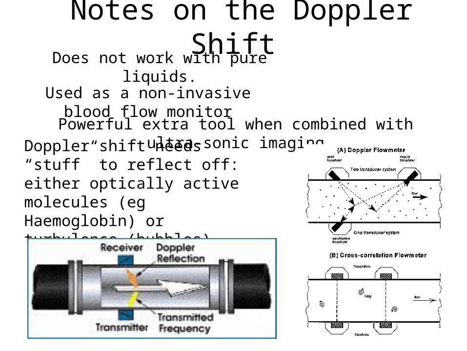
Doppler shift needs “stuff” to reflect off: either optically active molecules (eg Haemoglobin) or turbulence (bubbles)
Does not work with pure liquids.
Used as a non-invasive blood flow monitor
Powerful extra tool when combined with ultra-sonic imaging
Notes on the Doppler Shift
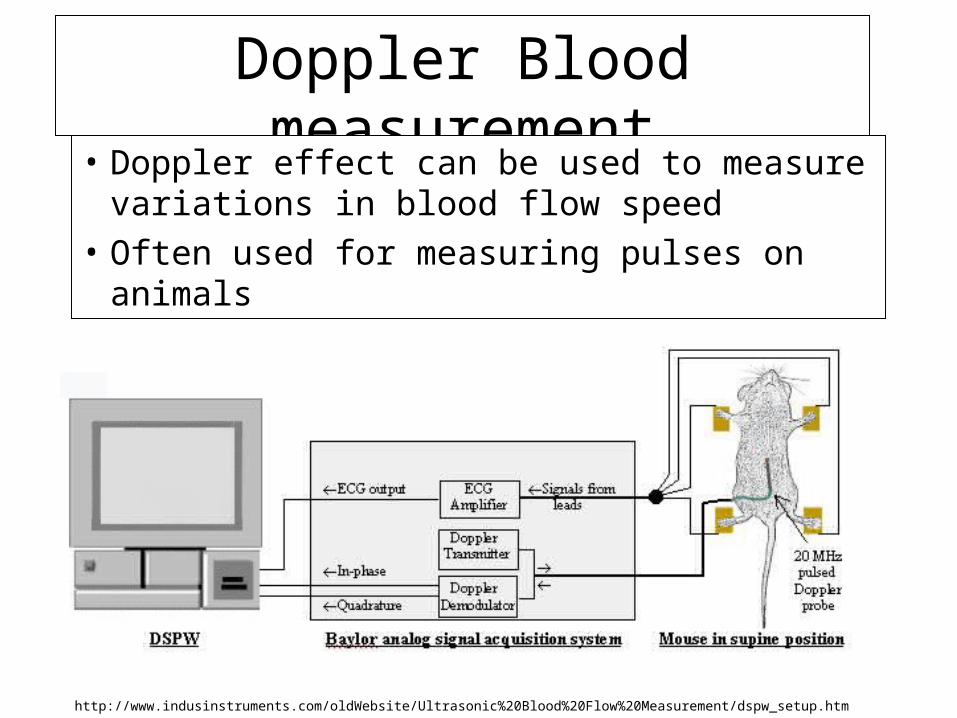
Doppler Blood measurement
• Doppler effect can be used to measure variations in blood flow speed
• Often used for measuring pulses on animals
http://www.indusinstruments.com/oldWebsite/Ultrasonic%20Blood%20Flow%20Measurement/dspw_setup.htm
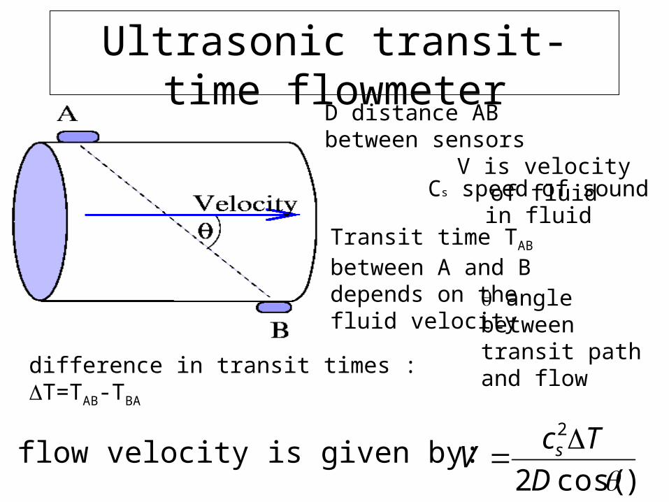
Ultrasonic transit-time flowmeter
Transit time TAB between A and B depends on the fluid velocity
)cos(2
2
D
TcV s
difference in transit times : T=TAB-TBA
D distance AB between sensors
angle between transit path and flow
V is velocity of fluidCs speed of sound in fluid
The flow velocity is given by:


