30
Lecture 7 Dr. Mahmoud Khedr

Lecture 7
Dr. Mahmoud Khedr

© 2002 The McGraw-Hill Companies, Inc. All rights reserved.
MECHANICS OF MATERIALS
Th
ird
Ed
ition
Beer • Johnston • DeWolf
4 - 2
Pure Bending
Pure Bending: Prismatic members
subjected to equal and opposite couples
acting in the same longitudinal plane

© 2002 The McGraw-Hill Companies, Inc. All rights reserved.
MECHANICS OF MATERIALS
Th
ird
Ed
ition
Beer • Johnston • DeWolf
4 - 3
Pure Bending
SFD
(lb)
BMD
(lb.in)
-
+
- 960
80
80

© 2002 The McGraw-Hill Companies, Inc. All rights reserved.
MECHANICS OF MATERIALS
Th
ird
Ed
ition
Beer • Johnston • DeWolf
4 - 4
Other Loading Types
• Principle of Superposition: The normal
stress due to pure bending may be
combined with the normal stress due to
axial loading and shear stress due to
shear loading to find the complete state
of stress.
• Eccentric Loading: Axial loading which
does not pass through section centroid
produces internal forces equivalent to an
axial force and a couple
• Transverse Loading: Concentrated or
distributed transverse load produces
internal forces equivalent to a shear
force and a couple
© 2002 The McGraw-Hill Companies, Inc. All rights reserved.
MECHANICS OF MATERIALS
Th
ird
Ed
ition
Beer • Johnston • DeWolf
4 - 5
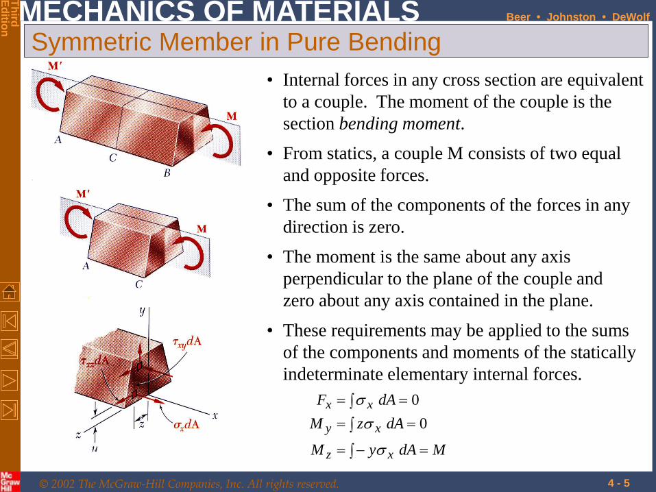
Symmetric Member in Pure Bending
MdAyM
dAzM
dAF
xz
xy
xx
0
0
• These requirements may be applied to the sums
of the components and moments of the statically
indeterminate elementary internal forces.
• Internal forces in any cross section are equivalent
to a couple. The moment of the couple is the
section bending moment.
• From statics, a couple M consists of two equal
and opposite forces.
• The sum of the components of the forces in any
direction is zero.
• The moment is the same about any axis
perpendicular to the plane of the couple and
zero about any axis contained in the plane.

© 2002 The McGraw-Hill Companies, Inc. All rights reserved.
MECHANICS OF MATERIALS
Th
ird
Ed
ition
Beer • Johnston • DeWolf
4 - 6
Bending Deformations
Beam with a plane of symmetry in pure
bending:
• member remains symmetric
• bends uniformly to form a circular arc
• cross-sectional plane passes through arc center
and remains planar
• length of top decreases and length of bottom
increases
• a neutral surface must exist that is parallel to the
upper and lower surfaces and for which the length
does not change
• stresses and strains are negative (compressive)
above the neutral plane and positive (tension)
below it

© 2002 The McGraw-Hill Companies, Inc. All rights reserved.
MECHANICS OF MATERIALS
Th
ird
Ed
ition
Beer • Johnston • DeWolf
4 - 7
Strain Due to Bending
Consider a beam segment of length L.
After deformation, the length of the neutral
surface remains L. At other sections,
mx
mm
x
c
y
cρ
c
yy
L
yyLL
yL
or
linearly) ries(strain va
© 2002 The McGraw-Hill Companies, Inc. All rights reserved.
MECHANICS OF MATERIALS
Th
ird
Ed
ition
Beer • Johnston • DeWolf
4 - 8
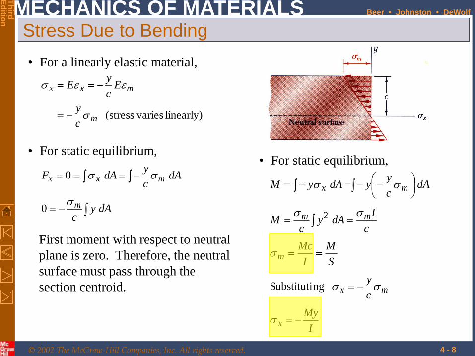
Stress Due to Bending
• For a linearly elastic material,
linearly) varies(stressm
mxx
c
y
Ec
yE
• For static equilibrium,
dAyc
dAc
ydAF
m
mxx
0
0
First moment with respect to neutral
plane is zero. Therefore, the neutral
surface must pass through the
section centroid.
• For static equilibrium,
I
My
c
y
S
M
I
Mc
c
IdAy
cM
dAc
yydAyM
x
mx
m
mm
mx
ngSubstituti
2

© 2002 The McGraw-Hill Companies, Inc. All rights reserved.
MECHANICS OF MATERIALS
Th
ird
Ed
ition
Beer • Johnston • DeWolf
4 - 9
Beam Section Properties
• The maximum normal stress due to bending,
modulussection
inertia ofmoment section
c
IS
I
S
M
I
Mcm
A beam section with a larger section modulus
will have a lower maximum stress
• Consider a rectangular beam cross section,
Ahbhh
bh
c
IS
613
61
3
121
2
Between two beams with the same cross
sectional area, the beam with the greater depth
will be more effective in resisting bending.
• Structural steel beams are designed to have a
large section modulus.

© 2002 The McGraw-Hill Companies, Inc. All rights reserved.
MECHANICS OF MATERIALS
Th
ird
Ed
ition
Beer • Johnston • DeWolf
4 - 10
Properties of American Standard Shapes

© 2002 The McGraw-Hill Companies, Inc. All rights reserved.
MECHANICS OF MATERIALS
Th
ird
Ed
ition
Beer • Johnston • DeWolf
4 - 11
Deformations in a Transverse Cross Section
• Deformation due to bending moment M is
quantified by the curvature of the neutral surface
EI
M
I
Mc
EcEcc
mm
11
• Although cross sectional planes remain planar
when subjected to bending moments, in-plane
deformations are nonzero,
yyxzxy
• Expansion above the neutral surface and
contraction below it cause an in-plane curvature,
curvature canticlasti 1
© 2002 The McGraw-Hill Companies, Inc. All rights reserved.
MECHANICS OF MATERIALS
Th
ird
Ed
ition
Beer • Johnston • DeWolf
4 - 12
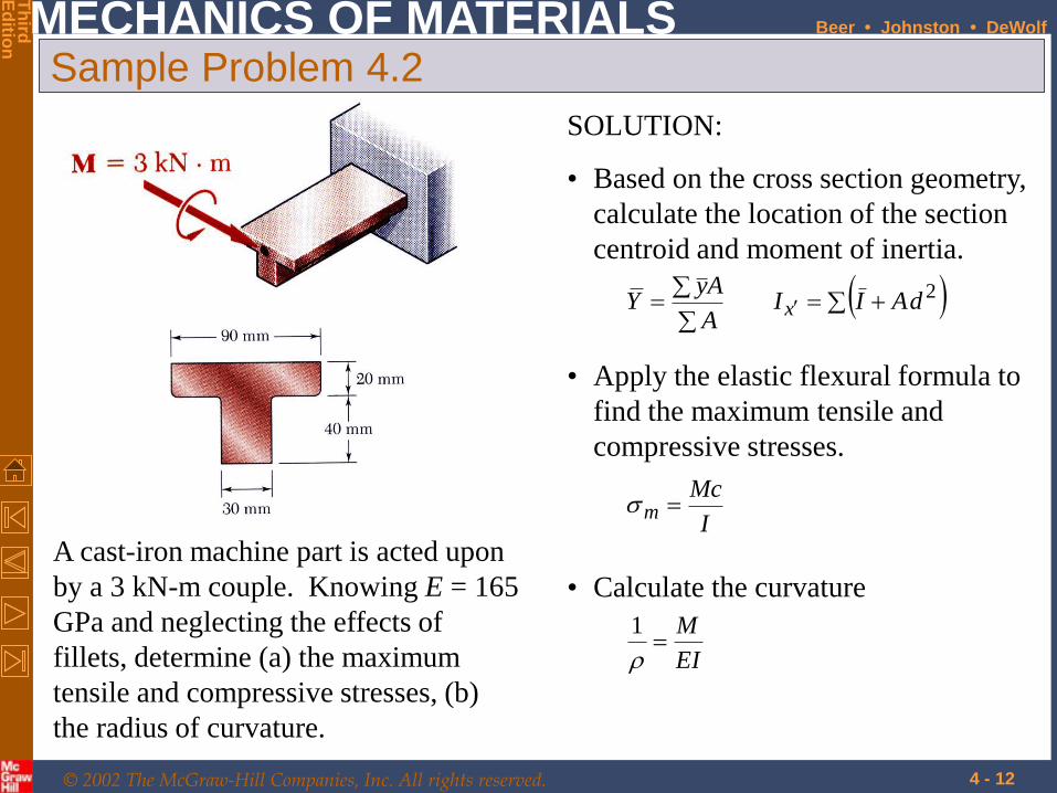
Sample Problem 4.2
A cast-iron machine part is acted upon
by a 3 kN-m couple. Knowing E = 165
GPa and neglecting the effects of
fillets, determine (a) the maximum
tensile and compressive stresses, (b)
the radius of curvature.
SOLUTION:
• Based on the cross section geometry,
calculate the location of the section
centroid and moment of inertia.
2dAIIA
AyY x
• Apply the elastic flexural formula to
find the maximum tensile and
compressive stresses.
I
Mcm
• Calculate the curvature
EI
M
1

© 2002 The McGraw-Hill Companies, Inc. All rights reserved.
MECHANICS OF MATERIALS
Th
ird
Ed
ition
Beer • Johnston • DeWolf
4 - 13
SOLUTION:
Based on the cross section geometry, calculate
the location of the section centroid and
moment of inertia.
mm 383000
10114 3
A
AyY
3
3
3
32
101143000
104220120030402
109050180090201
mm ,mm ,mm Area,
AyA
Ayy
49-3
2312123
121
231212
m10868 mm10868
18120040301218002090
I
dAbhdAIIx
© 2002 The McGraw-Hill Companies, Inc. All rights reserved.
MECHANICS OF MATERIALS
Th
ird
Ed
ition
Beer • Johnston • DeWolf
4 - 14
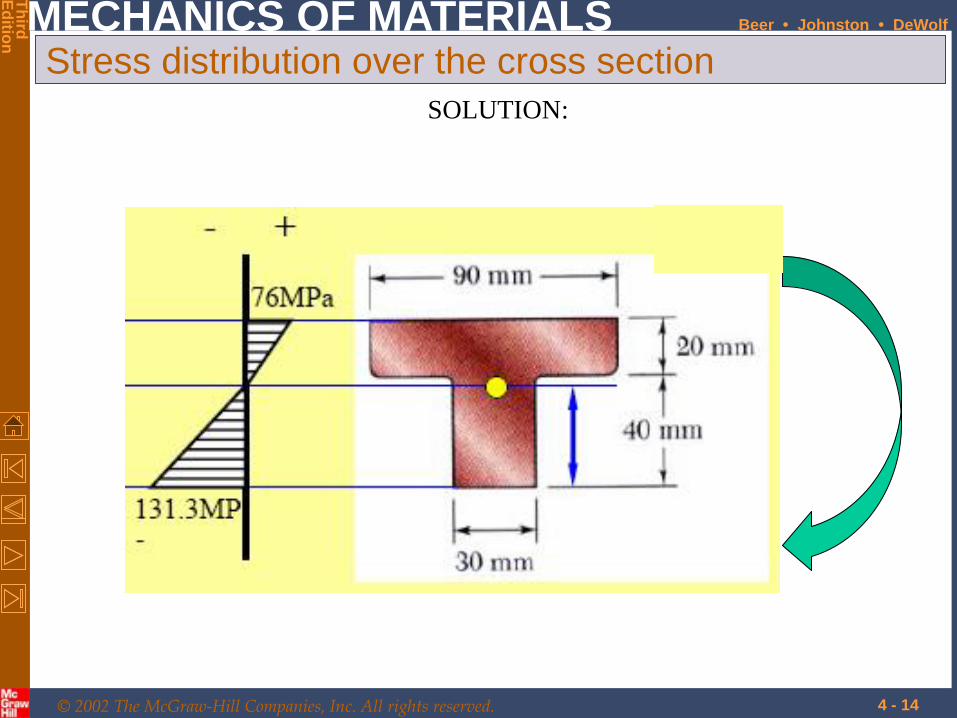
Stress distribution over the cross section
SOLUTION:
© 2002 The McGraw-Hill Companies, Inc. All rights reserved.
MECHANICS OF MATERIALS
Th
ird
Ed
ition
Beer • Johnston • DeWolf
4 - 15
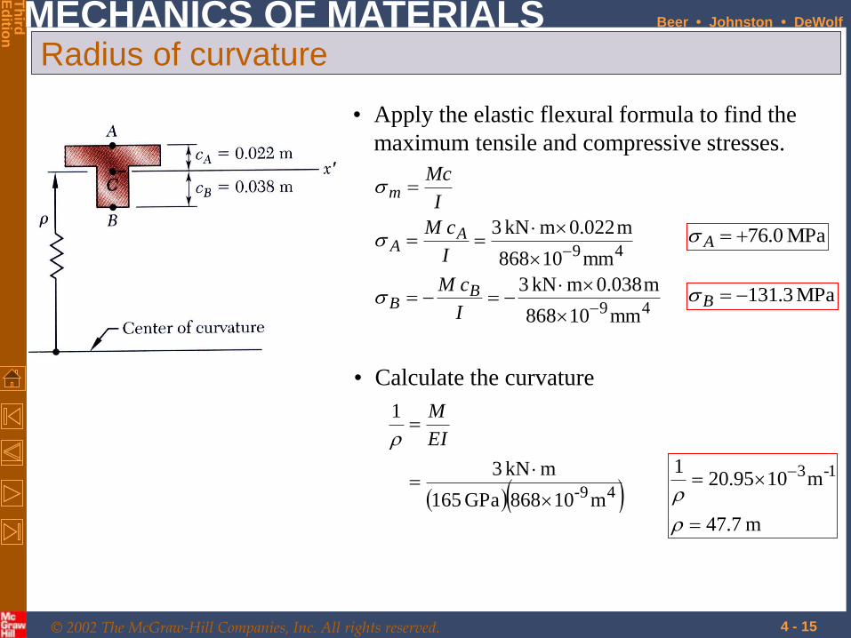
Radius of curvature
• Apply the elastic flexural formula to find the
maximum tensile and compressive stresses.
49
49
mm10868
m038.0mkN 3
mm10868
m022.0mkN 3
I
cM
I
cM
I
Mc
BB
AA
m
MPa 0.76A
MPa 3.131B
• Calculate the curvature
49- m10868GPa 165
mkN 3
1
EI
M
m 7.47
m1095.201 1-3
© 2002 The McGraw-Hill Companies, Inc. All rights reserved.
MECHANICS OF MATERIALS
Th
ird
Ed
ition
Beer • Johnston • DeWolf
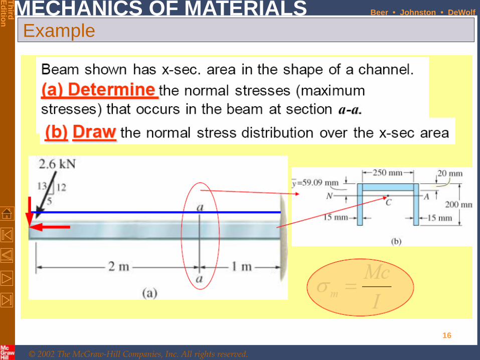
Example
16

© 2002 The McGraw-Hill Companies, Inc. All rights reserved.
MECHANICS OF MATERIALS
Th
ird
Ed
ition
Beer • Johnston • DeWolf
Solution
17
2m 1m
a
a
2.4 kN
1 kN
V
N
M
∑ moment = zero
∑ Fx = zero
∑ Fy = zero
V = 2.4 kN
N = 1 kN
M = 7.2 kN.m
FBD

© 2002 The McGraw-Hill Companies, Inc. All rights reserved.
MECHANICS OF MATERIALS
Th
ird
Ed
ition
Beer • Johnston • DeWolf
Solution
18
2m 1m
a
a
2.4 kN
1 kN
2.4 kN
1 kN
7.2 kN.m
NFD (kN)
SFD (kN)
BMD (kN.m)
+
1
- 2.4
+
0
- +
0
-
+
0
-
7.2
- 4.8

© 2002 The McGraw-Hill Companies, Inc. All rights reserved.
MECHANICS OF MATERIALS
Th
ird
Ed
ition
Beer • Johnston • DeWolf
Solution
19

© 2002 The McGraw-Hill Companies, Inc. All rights reserved.
MECHANICS OF MATERIALS
Th
ird
Ed
ition
Beer • Johnston • DeWolf
Solution
20

© 2002 The McGraw-Hill Companies, Inc. All rights reserved.
MECHANICS OF MATERIALS
Th
ird
Ed
ition
Beer • Johnston • DeWolf
Solution
21
σ max = 16.2 MPa (compression)
σ min = 𝟒.𝟖𝟐 ×𝟎.𝟎𝟓𝟗
𝟒𝟐.𝟐𝟔 ×𝟏𝟎−𝟔 = 6.8 MPa (tension)
Area = 5400 mm2
σ axial = N/A =1000/5400 = 0.2 MPa (tension)

© 2002 The McGraw-Hill Companies, Inc. All rights reserved.
MECHANICS OF MATERIALS
Th
ird
Ed
ition
Beer • Johnston • DeWolf
Solution
22
Stress distribution over the cross section
© 2002 The McGraw-Hill Companies, Inc. All rights reserved.
MECHANICS OF MATERIALS
Th
ird
Ed
ition
Beer • Johnston • DeWolf
4 - 23
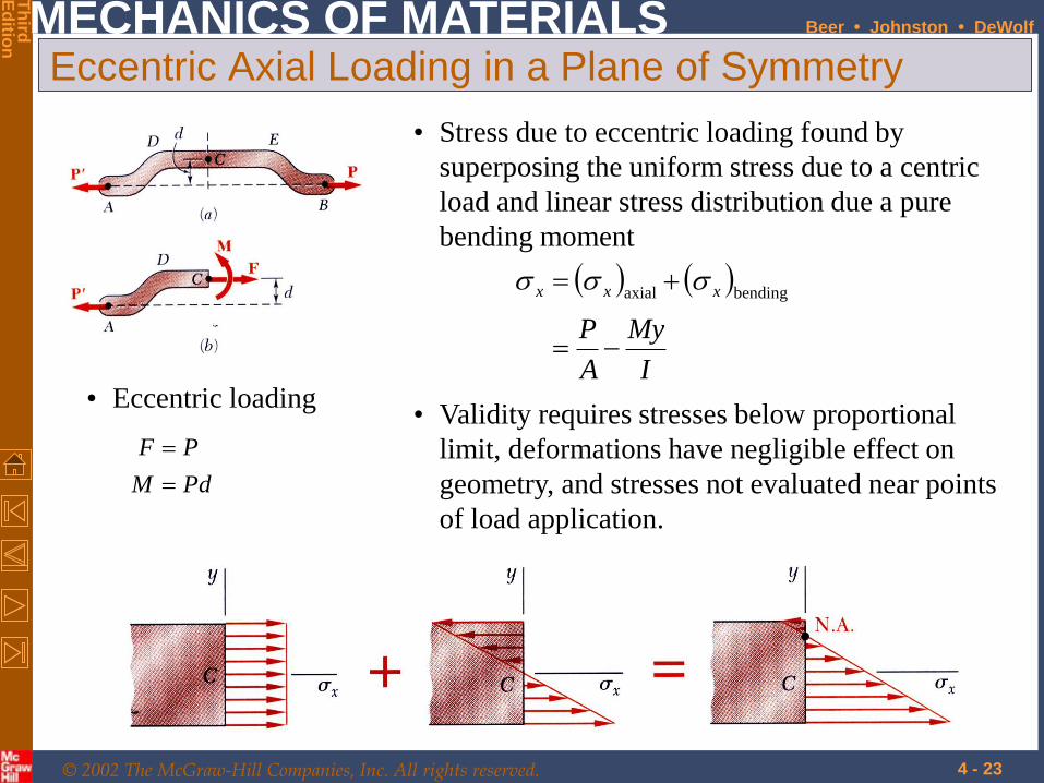
• Stress due to eccentric loading found by
superposing the uniform stress due to a centric
load and linear stress distribution due a pure
bending moment
I
My
A
P
xxx
bendingaxial
Eccentric Axial Loading in a Plane of Symmetry
• Eccentric loading
PdM
PF
• Validity requires stresses below proportional
limit, deformations have negligible effect on
geometry, and stresses not evaluated near points
of load application.
© 2002 The McGraw-Hill Companies, Inc. All rights reserved.
MECHANICS OF MATERIALS
Th
ird
Ed
ition
Beer • Johnston • DeWolf
4 - 24
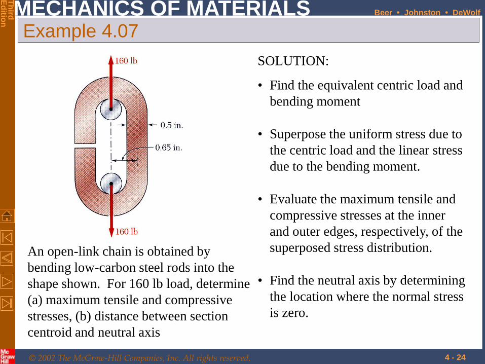
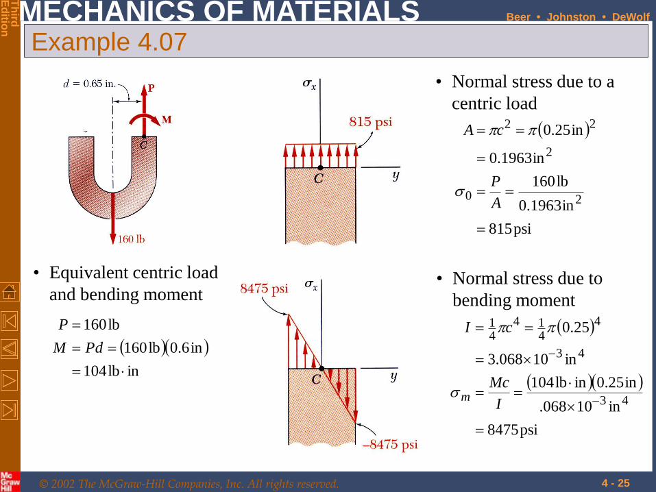
Example 4.07
An open-link chain is obtained by
bending low-carbon steel rods into the
shape shown. For 160 lb load, determine
(a) maximum tensile and compressive
stresses, (b) distance between section
centroid and neutral axis
SOLUTION:
• Find the equivalent centric load and
bending moment
• Superpose the uniform stress due to
the centric load and the linear stress
due to the bending moment.
• Evaluate the maximum tensile and
compressive stresses at the inner
and outer edges, respectively, of the
superposed stress distribution.
• Find the neutral axis by determining
the location where the normal stress
is zero.
© 2002 The McGraw-Hill Companies, Inc. All rights reserved.
MECHANICS OF MATERIALS
Th
ird
Ed
ition
Beer • Johnston • DeWolf
4 - 25
Example 4.07
• Equivalent centric load
and bending moment
inlb104
in6.0lb160
lb160
PdM
P
psi815
in1963.0
lb160
in1963.0
in25.0
20
2
22
A
P
cA
• Normal stress due to a
centric load
psi8475
in10068.
in25.0inlb104
in10068.3
25.0
43
43
4
414
41
I
Mc
cI
m
• Normal stress due to
bending moment
© 2002 The McGraw-Hill Companies, Inc. All rights reserved.
MECHANICS OF MATERIALS
Th
ird
Ed
ition
Beer • Johnston • DeWolf
4 - 26
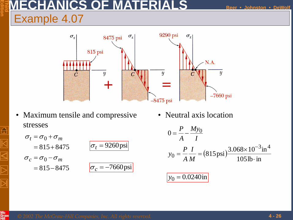
Example 4.07
• Maximum tensile and compressive
stresses
8475815
8475815
0
0
mc
mt
psi9260t
psi7660c
• Neutral axis location
inlb105
in10068.3psi815
0
43
0
0
M
I
A
Py
I
My
A
P
in0240.00 y

© 2002 The McGraw-Hill Companies, Inc. All rights reserved.
MECHANICS OF MATERIALS
Th
ird
Ed
ition
Beer • Johnston • DeWolf
4 - 27
Sample Problem 4.8
The largest allowable stresses for the cast
iron link are 30 MPa in tension and 120
MPa in compression. Determine the largest
force P which can be applied to the link.
SOLUTION:
• Determine an equivalent centric load and
bending moment.
• Evaluate the critical loads for the allowable
tensile and compressive stresses.
• The largest allowable load is the smallest
of the two critical loads.
From Sample Problem 2.4,
49
23
m10868
m038.0
m103
I
Y
A
• Superpose the stress due to a centric
load and the stress due to bending.

© 2002 The McGraw-Hill Companies, Inc. All rights reserved.
MECHANICS OF MATERIALS
Th
ird
Ed
ition
Beer • Johnston • DeWolf
4 - 28
Sample Problem 4.8
• Determine an equivalent centric and bending loads.
moment bending 028.0
load centric
m028.0010.0038.0
PPdM
P
d
• Evaluate critical loads for allowable stresses.
kN6.79MPa1201559
kN6.79MPa30377
PP
PP
B
A
kN 0.77P• The largest allowable load
• Superpose stresses due to centric and bending loads
P
PP
I
Mc
A
P
PPP
I
Mc
A
P
AB
AA
155910868
022.0028.0
103
37710868
022.0028.0
103
93
93
© 2002 The McGraw-Hill Companies, Inc. All rights reserved.
MECHANICS OF MATERIALS
Th
ird
Ed
ition
Beer • Johnston • DeWolf
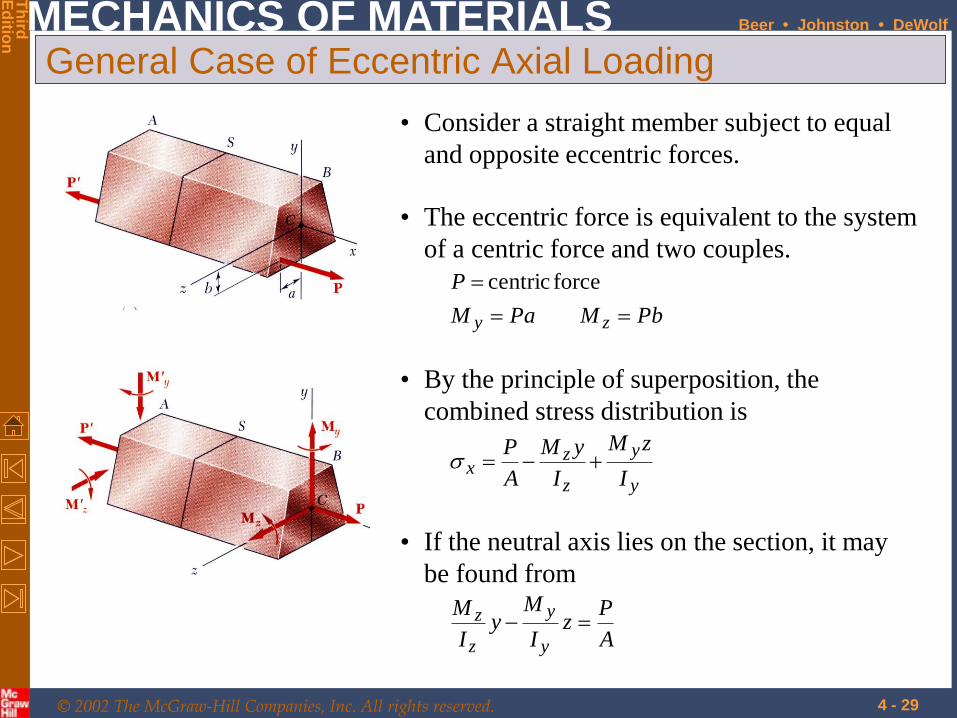
4 - 29
General Case of Eccentric Axial Loading
• Consider a straight member subject to equal
and opposite eccentric forces.
• The eccentric force is equivalent to the system
of a centric force and two couples.
PbMPaM
P
zy
force centric
• By the principle of superposition, the
combined stress distribution is
y
y
z
zx
I
zM
I
yM
A
P
• If the neutral axis lies on the section, it may
be found from
A
Pz
I
My
I
M
y
y
z
z
© 2002 The McGraw-Hill Companies, Inc. All rights reserved.
MECHANICS OF MATERIALS
Th
ird
Ed
ition
Beer • Johnston • DeWolf
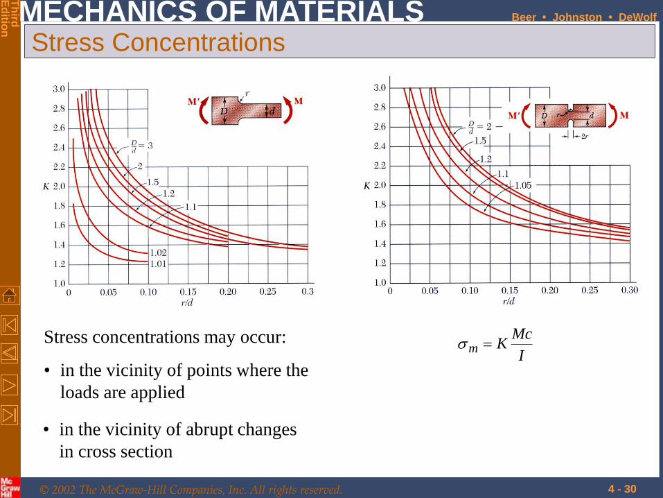
4 - 30
Stress Concentrations
Stress concentrations may occur:
• in the vicinity of points where the
loads are applied
I
McKm
• in the vicinity of abrupt changes
in cross section


