Lecture 9 – Mobility Management and Mobile Application Part (MAP)
Introduction .................................................................................................... 2 Mobility problem analysis ............................................................................. 2
Location of users ........................................................................................ 2 GSM solution of mobility management for circuit switching ....................... 5
Background on IP networks ....................................................................... 8 Mobile IP .................................................................................................. 10 Generalization: network state and connection state ................................. 10 Complication: private addressing in IP .................................................... 10 GPRS solution for mobility ...................................................................... 11 GPRS mobility state model ...................................................................... 12 Summary of GPRS mobility solution ...................................................... 13
Introduction to MAP .................................................................................... 14 MAP development roadmap .................................................................... 15 MAP services model ................................................................................ 17
The environment of MAP ............................................................................ 17 Addressing in MAP .................................................................................. 17 A view from above ................................................................................... 18 A view from underneath: MAP uses TCAP ............................................. 18 Data in HLR ............................................................................................. 19
Mobility management support in MAP ....................................................... 19 Location Management in MAP ................................................................ 19 Location of user in Mobile Terminated call ............................................. 21 Triangular routing in GSM ...................................................................... 22 Handover from one MSC to another MSC .............................................. 22 Security operations in MAP ..................................................................... 23 Subscriber management operations ......................................................... 24 Network requested PDP context activation ............................................. 24
Supplementary services operations in MAP ................................................ 25 Short Message service support in MAP ....................................................... 25
Short Message protocol stack .................................................................. 26 MO SMS service ...................................................................................... 27 MT SMS Service ...................................................................................... 28 Role of HLR in SMS service ................................................................... 28
Other MAP services ..................................................................................... 29 Call Completion to Busy Subscriber ........................................................ 29 Unstructured Supplementary Service Data .............................................. 30
Summary of mobility management and MAP ............................................. 31
Introduction Mobility management allows mobile users to make use of network services and be reachable to other communication parties while they move around. There are several aspects to mobility. We talk about terminal mobility referring to the fact that the terminal moves under the coverage area of the network or between networks. Similarly, we talk about user mobility. Service mobility refers to a phenomenon of moving between networks of different or the same type and across different devices for services access while a service is being used. The particular feature of mobility that users can move to networks owned by a different administration than their home network is called roaming. Mobility can be seamless or not. Mobility is seamless when service quality does not suffer when the device moves from one area to another or from one network to another. Seamless mobility for voice service means that the caller and callee cannot hear anything that they would perceive as “degraded quality” while a mobility action such as handover takes place. In practice, this probably means that duration of data loss is less than 50 to 70ms. Mobility management for voice services has proven to be very valuable. Users are quite willing to pay higher prices for a mobile service than for a fixed service. Mobility management is also quite complex. This is proven by the fact that actually only a handful of companies have been able to create a rich and successful portfolio of products supporting mobile communication services. MAP is the protocol that provides the mobility management for GSM and 3G networks. Other solutions for mobility management, mainly data protocol driven such as Mobile IP, have been proposed as well. None of them at least so far come even close in value to mobility management in GSM and 3G based on MAP. MAP provides the additional core network signaling capability that is needed besides ISUP because of the fact that the access is based on radio and the fact that users can move around with their mobile stations.
Mobility problem analysis Let us first discuss the nature of the technical problem of mobility and try to browse the solutions space. It turns out that scalability is a major concern in any mobility solution.
Location of users The location or finding of users in networks is based on directory numbers. When discussing wire line services we already noted that actually switching systems assume that dialed digits form routable numbers that are nicely
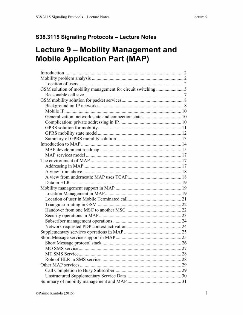
aligned with the network topology. Such numbers are allocated to network nodes block by block and the block size may be for example 1000 consecutive numbers. How numbers are actually analyzed? We depict the process of number analysis in Figure 9.1 The tree in Figure 9.1 is schematic only. Each box is a node taking for example 4×16=64 octets of memory. This would assume that a pointer takes 4 octets and that digits from 0, i, to F can be analyzed by looking up the corresponding ith pointer in the node.
If the number to be analyzed is ABCdefgh (i.e. 8 digits), the analysis starts by looking up the entry against A in the root node. A pointer is found to the next level node in which the second digit B can be analyzed. The analysis progresses through the tree, on each step one digit is consumed and a new node is found until the analysis ends and the pointer actually points to a bucket file housing the results. Let us denote the number of values that appear in each position of the number by v1, v2 ….vn. The size of the tree is: Size = 64 × (1 + v2 + v2×v3 + v2×v3×v4 + … + v2×… ×vn-1×vn). [1] To make things a bit simpler let us assume that in each position the number of used values is the same and equals to m. This is the average branching factor of the tree. The number of nodes in the tree then equals to: Nnodes = 1 + m + m2 + … + mn-1 = (mn – 1)/(m – 1). [2] The reason we introduce m and do not assume that all numbers are actually in use is simple. Turns out telephone numbering spaces are typically quite
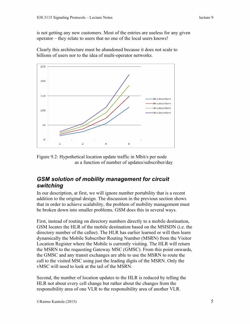
sparsely used. A typical feature of telephone numbering of variable length is that two numbers of the form: ABCd and ABCdx can not appear in the same numbering system, i.e. a short number always consumes a big block of numbers if fixed length numbers with a uniform number of digits is taken for comparison. The number of mobile users is around 7 Billion at the moment. Let us assume that about 3 digits are used for country code, 2 or 3 for operator code and 7 for subscriber numbers. On average this gives m12…13 = 7 × 10⁹ ⇒ (12 …13) lg m = 9 + lg 7 ⇒ m ≈ 5,7…6,6. [3] So, on average 5 to 7 digit values are used in each digit position of the directory numbers. Assuming the number length is 13 digits, the number of nodes in the analysis tree is about 1,5 billion. The size of the analysis tree would be about 95 GBytes. Worth noting is that when 1B new customers are connected the analysis tree needs about 10Gbytes of additional memory. A few years ago this in itself would have been a problem. Moore’s law has helped. Today one can build a computer with a main memory of this size. The difficulty lies elsewhere. Let us assume that mobile stations are let to move around and all exchanges are as in the wire line network with the difference that they have more memory and will analyze numbers till the last digits in their memory. The number of memory references for analyzing one number grows from about 4 till more than 10. This is not a problem. The problem with this approach lies in the fact that there are a lot of exchanges that would need to know about the whereabouts of all mobile users. Assuming that one MSC takes care of 200 000 users on average, there are some 35 000 MSCs in the world dealing with 7 Billion users. In this architecture each MSC would need to know the location of every mobile user with some accuracy. Assuming that each location update takes 50 bytes of signaling, the signaling traffic towards each node is depicted in Figure 9.2. For the purpose of ensuring integrity of the location information we would have to repeat the location updates on regular intervals. Even if nodes would be rather big, we would probably need several updates per day for each user. An added trouble is that the size of the tree keeps growing in every node even if the particular operator
is not getting any new customers. Most of the entries are useless for any given operator – they relate to users that no one of the local users knows! Clearly this architecture must be abandoned because it does not scale to billions of users nor to the idea of multi-operator networks.
Figure 9.2: Hypothetical location update traffic in Mbit/s per node as a function of number of updates/subscriber/day
GSM solution of mobility management for circuit switching In our description, at first, we will ignore number portability that is a recent addition to the original design. The discussion in the previous section shows that in order to achieve scalability, the problem of mobility management must be broken down into smaller problems. GSM does this in several ways. First, instead of routing on directory numbers directly to a mobile destination, GSM locates the HLR of the mobile destination based on the MSISDN (i.e. the directory number of the callee). The HLR has earlier learned or will then learn dynamically the Mobile Subscriber Routing Number (MSRN) from the Visitor Location Register where the Mobile is currently visiting. The HLR will return the MSRN to the requesting Gateway MSC (GMSC). From this point onwards, the GMSC and any transit exchanges are able to use the MSRN to route the call to the visited MSC using just the leading digits of the MSRN. Only the vMSC will need to look at the tail of the MSRN. Second, the number of location updates to the HLR is reduced by telling the HLR not about every cell change but rather about the changes from the responsibility area of one VLR to the responsibility area of another VLR.
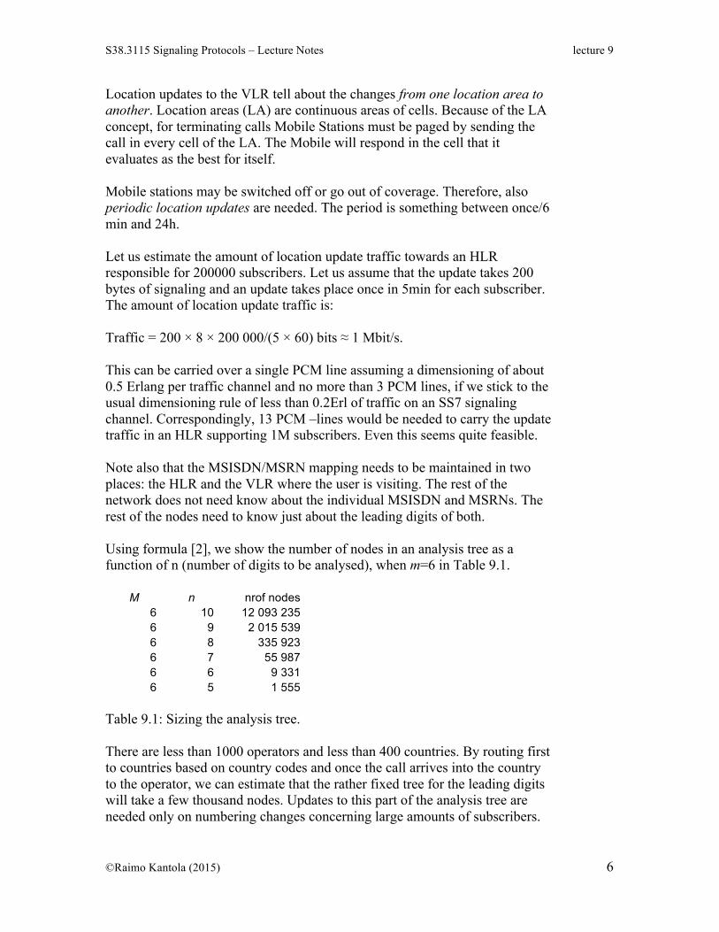
Location updates to the VLR tell about the changes from one location area to another. Location areas (LA) are continuous areas of cells. Because of the LA concept, for terminating calls Mobile Stations must be paged by sending the call in every cell of the LA. The Mobile will respond in the cell that it evaluates as the best for itself. Mobile stations may be switched off or go out of coverage. Therefore, also periodic location updates are needed. The period is something between once/6 min and 24h. Let us estimate the amount of location update traffic towards an HLR responsible for 200000 subscribers. Let us assume that the update takes 200 bytes of signaling and an update takes place once in 5min for each subscriber. The amount of location update traffic is: Traffic = 200 × 8 × 200 000/(5 × 60) bits ≈ 1 Mbit/s. This can be carried over a single PCM line assuming a dimensioning of about 0.5 Erlang per traffic channel and no more than 3 PCM lines, if we stick to the usual dimensioning rule of less than 0.2Erl of traffic on an SS7 signaling channel. Correspondingly, 13 PCM –lines would be needed to carry the update traffic in an HLR supporting 1M subscribers. Even this seems quite feasible. Note also that the MSISDN/MSRN mapping needs to be maintained in two places: the HLR and the VLR where the user is visiting. The rest of the network does not need know about the individual MSISDN and MSRNs. The rest of the nodes need to know just about the leading digits of both. Using formula [2], we show the number of nodes in an analysis tree as a function of n (number of digits to be analysed), when m=6 in Table 9.1.
Table 9.1: Sizing the analysis tree. There are less than 1000 operators and less than 400 countries. By routing first to countries based on country codes and once the call arrives into the country to the operator, we can estimate that the rather fixed tree for the leading digits will take a few thousand nodes. Updates to this part of the analysis tree are needed only on numbering changes concerning large amounts of subscribers.
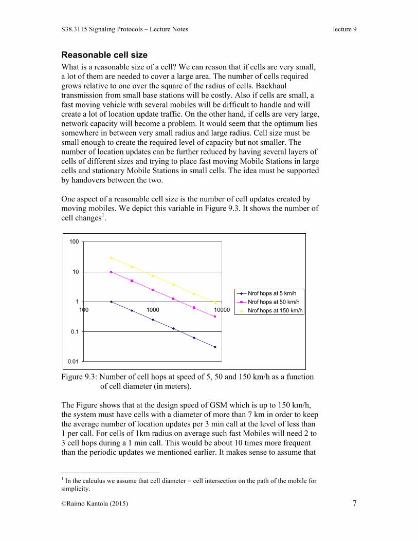
Reasonable cell size What is a reasonable size of a cell? We can reason that if cells are very small, a lot of them are needed to cover a large area. The number of cells required grows relative to one over the square of the radius of cells. Backhaul transmission from small base stations will be costly. Also if cells are small, a fast moving vehicle with several mobiles will be difficult to handle and will create a lot of location update traffic. On the other hand, if cells are very large, network capacity will become a problem. It would seem that the optimum lies somewhere in between very small radius and large radius. Cell size must be small enough to create the required level of capacity but not smaller. The number of location updates can be further reduced by having several layers of cells of different sizes and trying to place fast moving Mobile Stations in large cells and stationary Mobile Stations in small cells. The idea must be supported by handovers between the two. One aspect of a reasonable cell size is the number of cell updates created by moving mobiles. We depict this variable in Figure 9.3. It shows the number of cell changes1.
0.01
0.1
1
10
100
100 1000 10000
Nrof hops at 5 km/hNrof hops at 50 km/hNrof hops at 150 km/h
Figure 9.3: Number of cell hops at speed of 5, 50 and 150 km/h as a function of cell diameter (in meters). The Figure shows that at the design speed of GSM which is up to 150 km/h, the system must have cells with a diameter of more than 7 km in order to keep the average number of location updates per 3 min call at the level of less than 1 per call. For cells of 1km radius on average such fast Mobiles will need 2 to 3 cell hops during a 1 min call. This would be about 10 times more frequent than the periodic updates we mentioned earlier. It makes sense to assume that
1 In the calculus we assume that cell diameter = cell intersection on the path of the mobile for simplicity.
whatever the mobiles do, the number of updates should on average not grow more than 10 times over the number of updates dictated by periodic updates. There is one more aspect to cell size, namely power consumption. Most power in mobiles is consumed in sending or heavy processing. A location update will most likely wake up the main processor on the mobile, consuming power. Frequent location updates will deplete the mobiles battery quickly. From the point of view of power saving, the more the mobile can sleep the better. Cellular phone and network vendors have put a lot of effort in creating more tricks that allow the mobile to sleep as much as possible. For cellular radios the need for power saving is a major design consideration. For example WLAN suffers from high power consumption because power saving has never been a driving design consideration and is something that cannot be changed afterwards. The conclusion is that from the point of view of scaling the location update traffic onto a reasonable level, a true mobile system must have support for cells of one to several kilometers in diameter. Additional capacity can be created if cells with a radius of less than 1km can be used as well. This reasoning is aligned with what actually has happened in the past. During the 1990s GSM had several competitors such as CT2, DECT and PCN that provided small cells only. These systems were gradually pushed away from the market. (Fair enough, besides cell sizes there are many other good reasons why they failed). This reasoning also suggests that WLAN or a similar system will have a hard time in trying to win over GSM and 3G as a wide area mobile solution unless a new variant will support larger cells.
GSM mobility solution for packet services
Background on IP networks There are differences in requirements for mobility management in circuit and packet networks. Let us first give some background on IP networks that in practice are the target networks for packet services in GSM. In IP networks, network service is connectionless and best effort. This means that the sender creates a packet with a destination address, hands it to the network and hopes that the network will be able to deliver it to the destination. There are no acknowledgements on IP level, so the network does not offer any assurance of delivery. Each packet is processed in the network nodes called routers independently of the next packet irrespective that they may belong to the same flow. A flow is a sequence of packets all having the same pair of source and destination IP addresses and the same pair of source and destination TCP/UDP ports and using the same protocol (e.g. TCP, UDP or SCTP) such that the time distance between two consecutive packets is less than some time limit.
Routing in IP network is dynamic, i.e. based on dynamic routing protocols. The job of routing protocols is to create forwarding tables in the routers. A router reads the destination address in the current packet, looks up the address in the forwarding table based on longest match, finds a forwarding entry and directs the packet onto the outgoing port found in the forwarding entry. Longest match means that the router looks for an entry in the forwarding table such that the highest number of leading bits in the destination address match with the entry among all other entries. In a high-capacity router, this match algorithm is executed on silicon (ASIC) When the status of links or routers in the global Internet changes, the change is noticed by the nodes and reported to the routing protocols. The routing protocols distribute the information about the change possibly applying policy rules and aggregation of information and each node that receives the info will calculate a new forwarding table. Usually, hosts (a mobile station that connects to an IP network will become a host in the IP network) do not appear in forwarding tables. This would lead to very large tables and to a non-scalable need of updating host status information across the IP network. Instead, a routing entry is identified by an IP address prefix of variable length. The IP –address of a host may be static or may be assigned upon establishing a network connection dynamically (using for example the DHCP protocol). The value assigned will depend on the position of the network attachment of the user in the network topology. The core of the Internet (non-default routers) has routing tables that have a few hundred thousand entries (half a million). The size of the forwarding table is seen as a serious problem at the moment. The larger the tables are, the more costly the core routers will become and the harder they will be to maintain. A combination of a large fast memory for the forwarding table and the longest match search consumes a lot of power in the router. Stability of the core routing tables is another problem. For example when an important broadband fiber connection (or a set of connections on an underwater cable) broke because of an earthquake under Pacific, it took several days for the routing tables to stabilize. The scalability of routing favors a mobility solution that assigns a new IP address to a moving mobile on cell change (or a change from a set of cells to another). Only if the IP addresses of mobiles in a particular cell are aligned with the network topology, the routing will not be impacted by mobility. TCP is used for most data transport over IP. It assumes that a session for which TCP tries to guarantee reliable delivery is identified by originating and destination IP-addresses and port numbers and the protocol (TCP in this case).
It follows that the session breaks down if one of the parties in the session changes its IP address. From this point of view the solution that follows from routing scalability does not fly. Mobility will not be seamless but leads to communication failures.
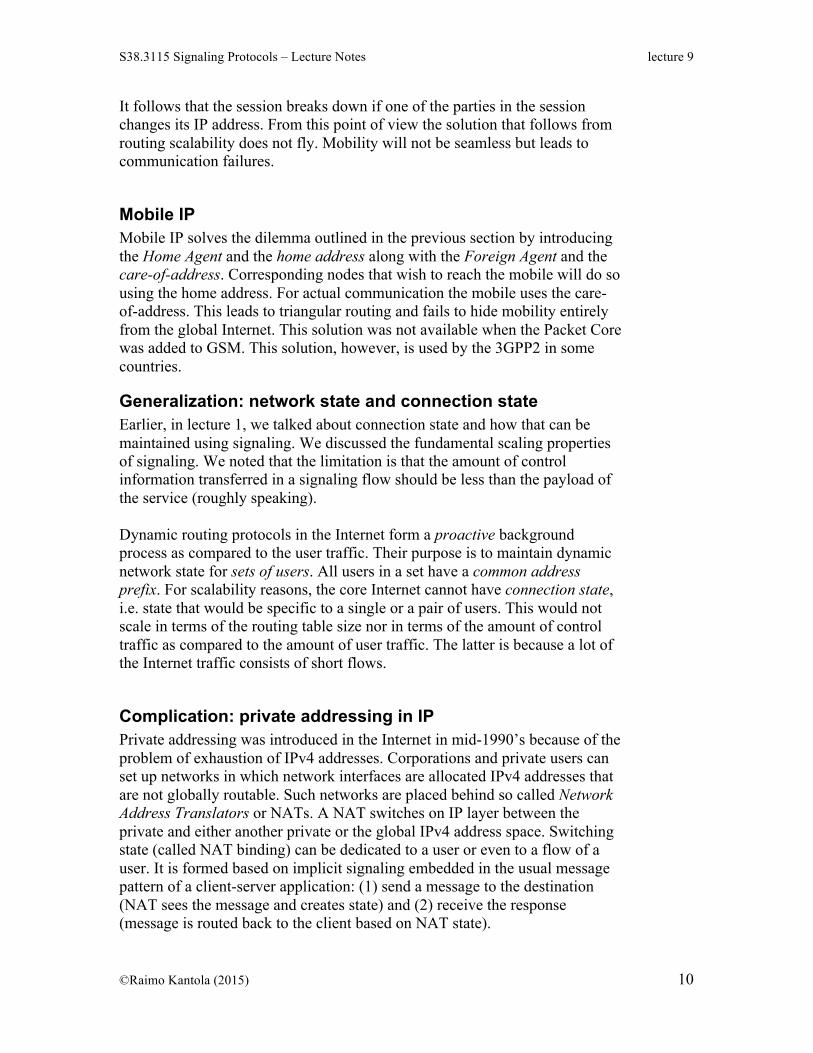
Mobile IP Mobile IP solves the dilemma outlined in the previous section by introducing the Home Agent and the home address along with the Foreign Agent and the care-of-address. Corresponding nodes that wish to reach the mobile will do so using the home address. For actual communication the mobile uses the care-of-address. This leads to triangular routing and fails to hide mobility entirely from the global Internet. This solution was not available when the Packet Core was added to GSM. This solution, however, is used by the 3GPP2 in some countries.
Generalization: network state and connection state Earlier, in lecture 1, we talked about connection state and how that can be maintained using signaling. We discussed the fundamental scaling properties of signaling. We noted that the limitation is that the amount of control information transferred in a signaling flow should be less than the payload of the service (roughly speaking). Dynamic routing protocols in the Internet form a proactive background process as compared to the user traffic. Their purpose is to maintain dynamic network state for sets of users. All users in a set have a common address prefix. For scalability reasons, the core Internet cannot have connection state, i.e. state that would be specific to a single or a pair of users. This would not scale in terms of the routing table size nor in terms of the amount of control traffic as compared to the amount of user traffic. The latter is because a lot of the Internet traffic consists of short flows.
Complication: private addressing in IP Private addressing was introduced in the Internet in mid-1990’s because of the problem of exhaustion of IPv4 addresses. Corporations and private users can set up networks in which network interfaces are allocated IPv4 addresses that are not globally routable. Such networks are placed behind so called Network Address Translators or NATs. A NAT switches on IP layer between the private and either another private or the global IPv4 address space. Switching state (called NAT binding) can be dedicated to a user or even to a flow of a user. It is formed based on implicit signaling embedded in the usual message pattern of a client-server application: (1) send a message to the destination (NAT sees the message and creates state) and (2) receive the response (message is routed back to the client based on NAT state).
As a result: usually a device behind a NAT is not reachable directly from the global Internet unless the device first takes the initiative and sends some message that creates NAT state. The NAT solution scales for short user data flows and as a side effect protects the user device from unwanted traffic.
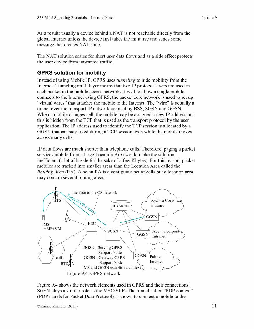
GPRS solution for mobility Instead of using Mobile IP, GPRS uses tunneling to hide mobility from the Internet. Tunneling on IP layer means that two IP protocol layers are used in each packet in the mobile access network. If we look how a single mobile connects to the Internet using GPRS, the packet core network is used to set up “virtual wires” that attaches the mobile to the Internet. The “wire” is actually a tunnel over the transport IP network connecting BSS, SGSN and GGSN. When a mobile changes cell, the mobile may be assigned a new IP address but this is hidden from the TCP that is used as the transport protocol by the user application. The IP address used to identify the TCP session is allocated by a GGSN that can stay fixed during a TCP session even while the mobile moves across many cells. IP data flows are much shorter than telephone calls. Therefore, paging a packet services mobile from a large Location Area would make the solution inefficient (a lot of hassle for the sake of a few Kbytes). For this reason, packet mobiles are tracked into smaller areas than the Location Area called the Routing Area (RA). Also an RA is a contiguous set of cells but a location area may contain several routing areas.
Raimo Kantola – S- 2007 Signaling Protocols 9 - 19
In GPRS, SGSN takes care of mobility and GGSN is the interface node to other networks (GSM 2+)
BSC
BTS
cells
BSCMS= ME+SIM
BTS
Interface to the CS network
SGSN
GGSN
Xyz – a CorporateIntranet
GGSN
GGSN
HLR/AC/EIR
PublicInternet
Abc – a corporateIntranet
SGSN - Serving GPRSSupport Node
GGSN - Gateway GPRSSupport Node
MS and GGSN establish a context
Tunnel/PDP context
Figure 9.4: GPRS network.
Figure 9.4 shows the network elements used in GPRS and their connections. SGSN plays a similar role as the MSC/VLR. The tunnel called “PDP context” (PDP stands for Packet Data Protocol) is shown to connect a mobile to the
Internet through several access and packet core network elements. HLR is used to grant or deny access to a particular packet data network behind a GGSN and to keep track of the location of the mobile with the accuracy of an SGSN.
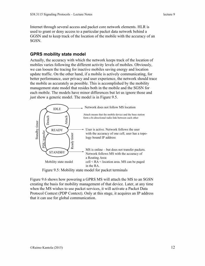
GPRS mobility state model Actually, the accuracy with which the network keeps track of the location of mobiles varies following the different activity levels of mobiles. Obviously, we can loosen the tracing for inactive mobiles saving energy and location update traffic. On the other hand, if a mobile is actively communicating, for better performance, user privacy and user experience, the network should trace the mobile as accurately as possible. This is accomplished by the mobility management state model that resides both in the mobile and the SGSN for each mobile. The models have minor differences but let us ignore those and just show a generic model. The model is in Figure 9.5.
Raimo Kantola – S- 2007 Signaling Protocols 9 - 20
GPRS mobility management states/ MS in MS and in SGSN
IDLE
STANDBY
READY
Mobility state model
Atta
ch
Det
ach
Rea
dy ti
mer
Stan
dby
timer
PDU
tran
sfer
Network does not follow MS location
User is active. Network follows the userwith the accuracy of one cell, user has a topo-logy bound IP address
MS is online – but does not transfer packets. Network follows MS with the accuracy ofa Routing Area:cell < RA < location area. MS can be pagedin the RA.
this is a bit simplified
Attach means that the mobile device and the base stationform a bi-directional radio link between each other
Figure 9.5: Mobility state model for packet terminals
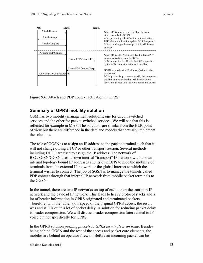
Figure 9.6 shows how powering a GPRS MS will attach the MS to an SGSN creating the basis for mobility management of that device. Later, at any time when the MS wishes to use packet services, it will activate a Packet Data Protocol Context (PDP Context). Only at this stage, it acquires an IP address that it can use for global communication.
Raimo Kantola – S- 2008 Signaling Protocols 9 - 21
GPRS attach and PDP contextactivation
MS SGSN GGSNAttach Request
Attach Accept
Attach Complete
When MS is powered on, it will perform anattach towards the SGSN,After performing, identification, authentication,IMEI check and location update, SGSN respondsMS acknowledges the receipt of AA, MS is nowattached
Activate PDP Context
Create PDP Context Req
Create PDP Context Resp
Activate PDP Context Accept
When MS needs IP connectivity, it initiates PDPcontext activation towards SGSN.SGSN routes the Act Req to the GGSN specifiedby the APN parameter in the Activate Req
GGSN responds with IP address, QoS and otherparameters.SGSN passes the parameters to MS, this completesthe PDP context activation. MS is now able toaccess the Packet Data Network behind the GGSN
Figure 9.6: Attach and PDP context activation in GPRS
Summary of GPRS mobility solution GSM has two mobility management solutions: one for circuit switched services and the other for packet switched services. We will see that this is reflected for example in MAP. The solutions are similar from the HLR point of view but there are difference in the data and models that actually implement the solutions. The role of GGSN is to assign an IP address to the packet terminal such that it will not change during a TCP or other transport session. Several methods including DHCP are used to assign the IP address. The network of BSC/SGSN/GGSN uses its own internal “transport” IP network with its own internal topology bound IP addresses and its own DNS to hide the mobility of terminals from the external IP network or the global Internet to which the terminal wishes to connect. The job of SGSN is to manage the tunnels called PDP context through that internal IP network from mobile packet terminals to the GGSN. In the tunnel, there are two IP networks on top of each other: the transport IP network and the payload IP network. This leads to heavy protocol stacks and a lot of header information in GPRS originated and terminated packets. Therefore, with the rather slow speed of the original GPRS access, the result was and still is quite a lot of packet delay. A solution for reducing packet delay is header compression. We will discuss header compression later related to IP voice but not specifically for GPRS. In the GPRS solution pushing packets to GPRS terminals is an issue. Besides being behind GGSN and the rest of the access and packet core elements, the mobiles are behind an operator firewall. Before an incoming packet can be
delivered to an inactive but powered mobile a lot must happen. Somehow the firewall must be traversed, the GGSN must be located and an IP address must be assigned to the mobile (actually the packet can not be formed in the first place if the destination does not have an IP address). Several solutions have been proposed but we will not discuss them in detail. Another aspect of GPRS mobility is roaming. Roaming means that mobiles are provided service while they are visiting foreign networks. Typically, all packet data traffic to and from the mobile traverses the home network. Then it is logical that it is the home network GGSN that assigns the Internet address to the mobile even in case the mobile is roaming. We call this home network breakout. There is a case of visited network breakout also. It is used for media under the so call IP Multimedia Subsystem (IMS). Pushing packets to mobiles is also a trust problem. If anyone could send packets to mobile terminals, they would become targets of DOS attacks. This would bring unwanted non-chargeable traffic to the air interface. This is completely unacceptable to the mobile operators and would be a huge nuisance to mobile users. Each non-wanted packet would most likely wake up the mobile and this would quickly drain the mobile’s battery while it would be on-line. So, a mobile resident firewall is really not a good option. Therefore, it is essential that the mobiles are protected by operator firewalls. One can take this reasoning one step further. Namely, if we accept the idea that a network based Firewall is essential to Mobile packet service for DOS attack protection, we can allow that Mobiles do not need globally unique IP addresses. A Firewall must look up many data fields in the packet on IP and transport protocol level and even on the application layer. So, without much of a performance burden it can do an address swap on IP layer. The conclusion is that actually IPv6 with its huge address space is probably not such a great idea for mobile terminals. Following this reasoning, at Comnet, we have developed the Customer Edge Switching (CES) technology. If adopted, CES would allow hosts in private address space to communicate with hosts in other private address space and filter all traffic based on policy.
Introduction to MAP Call setup in GSM and for circuit switched services in 3G is still based on ISUP like in ISDN. The purpose of MAP is to provide all the added signaling functionality required for mobility management in core networks and for several services that are part of the core GSM specification but are not included in ISDN. An example of such services is the short message service. It became part of GSM almost by accident. Short messages are carried over signaling channels in the access and the SS7 networks. The transport protocol is MAP.
The lumping of all kinds of requirements on MAP has resulted in a specification of some 1000 pages for one version of MAP. New functionality has been added into MAP gradually first by ETSI and later by the 3GPP in progressive releases. Deployment of the new releases does not take place over night. Therefore, a MAP specialist will know several releases. Looking at the history of ISDN and GSM and comparing the two systems, one can say that ISDN makes poor use of the fact that ISDN terminals are computers. For services implementation it relies on the network and tries to control carefully what the user can do with his or her terminal. GSM took a step towards recognizing that terminals are intelligent and will contain a lot of software. Terminal intelligence is important for managing mobility and short messaging make them to become more than phones. Consumer market economies of scale have served GSM well. Natural limiting factors for putting certain functions on Mobiles are that they are battery powered and sometimes out of coverage or out of power.
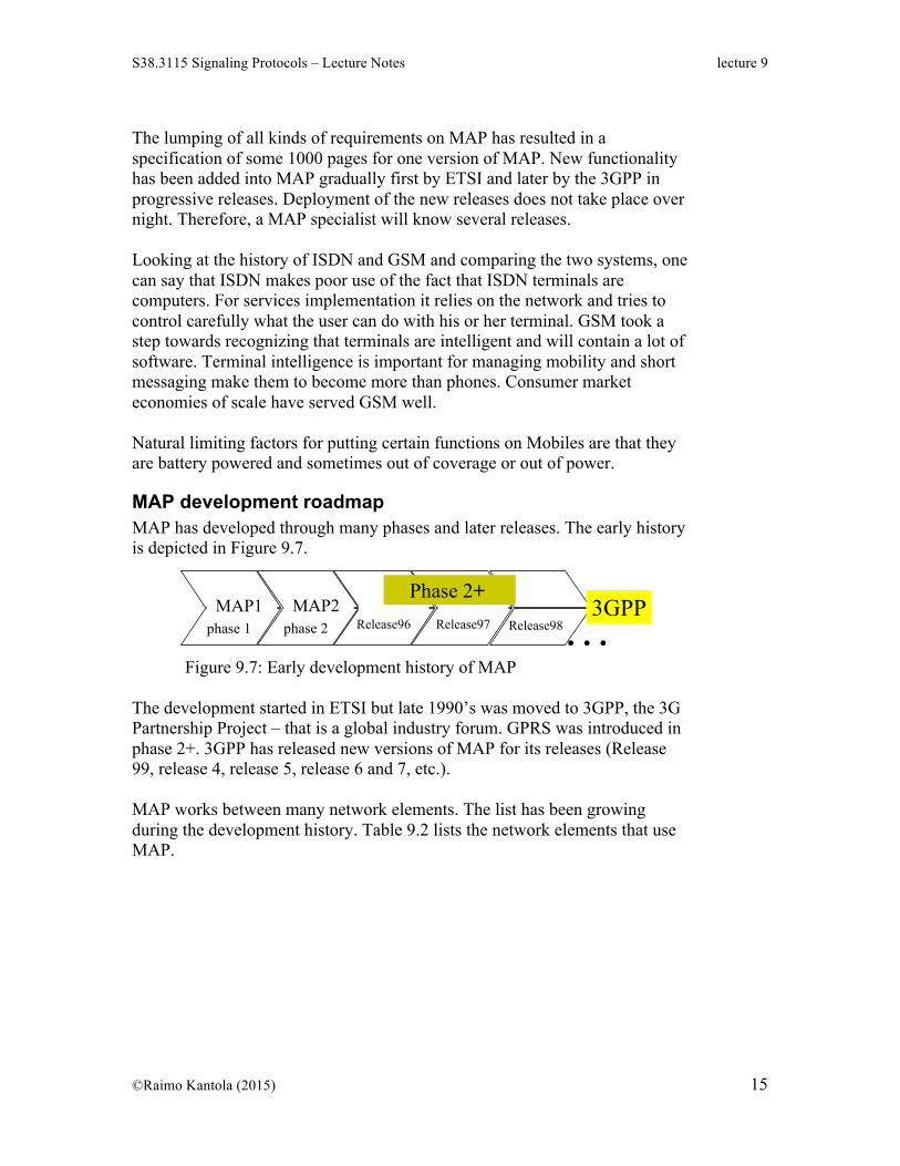
MAP development roadmap MAP has developed through many phases and later releases. The early history is depicted in Figure 9.7.
Raimo Kantola – S- 2007 Signaling Protocols 9 - 25
Milestones in MAP development
MAP1phase 1
MAP2phase 2 Release96 Release97
• In phase 2+ … versioning is per operation package.
• This supports the idea of deploying small sets of features at a time in the network.
• If a remote system does not understand the newest tricks,fall-back negotiation restores operation on the level of the previous version.
• Release98 3GPP TS 09.02 V7.11.0 in www.3gpp.org (03-2002), ETSI !3GPP
The development started in ETSI but late 1990’s was moved to 3GPP, the 3G Partnership Project – that is a global industry forum. GPRS was introduced in phase 2+. 3GPP has released new versions of MAP for its releases (Release 99, release 4, release 5, release 6 and 7, etc.). MAP works between many network elements. The list has been growing during the development history. Table 9.2 lists the network elements that use MAP.
Raimo Kantola – S- 2007 Signaling Protocols 9 - 26
MAP is used by many network elementsEIR Equipment Identity Register - usually integrated with HLR
GCR Group Call Register (does not appear in rel 7)
GGSN Gateway GPRS Support Node - for interfacing to IP or other PD networks
GMLC Gateway Mobile Location Center - for interfacing to Location Services
GMSC Gateway MSC - for routing calls from visited network
gsmSCF GSM Service Control Function - IN service control element
HLR Home Location Register - the key database
MSC Mobile services Switching Center
NPLR Number Portability Location Center - for locating an HLR
SGSN Serving GPRS Support Node - the "MSC/VLR" for PS services
SIWFSShared Interworking Function Server - for interfacing CS data services to IP or other PD networks (not in rel 7!)
SMS GWMSC SMS Gateway MSC - for terminating SMS routing
SMS IWMSC SMS Interworking MSC - for originating SMS routing
USSDC USSD Center - part of gsmSCFVBS/VGCS Anchor MSC Voice broadcast/group call service Anchor MSC
VBS/VGCS Relay MSC Voice broadcast/group call service relay MSC
VLR Visitor Location Register -in practice integrated with MSC
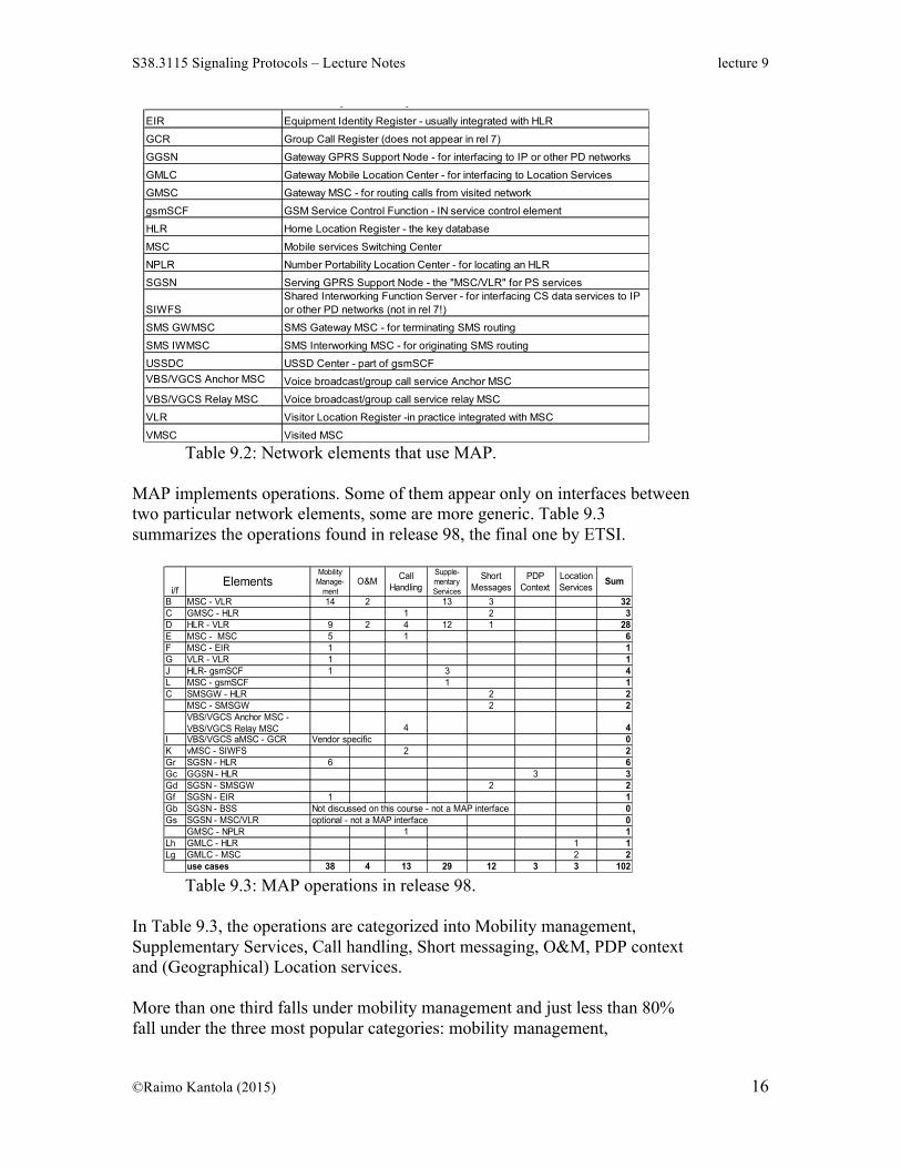
VMSC Visited MSC Table 9.2: Network elements that use MAP.
MAP implements operations. Some of them appear only on interfaces between two particular network elements, some are more generic. Table 9.3 summarizes the operations found in release 98, the final one by ETSI.
Raimo Kantola – S- 2007 Signaling Protocols 9 - 32
MAP -operations in Release98/ETSI/3GPP
The table corresponds to MAPv2+ Release98 (3GPP) This lecture does not discuss MSC-VLR interface operations nor O&M –operations, nor location services, nor Group Calls.
I VBS/VGCS aMSC - GCR Vendor specific 0K vMSC - SIWFS 2 2Gr SGSN - HLR 6 6Gc GGSN - HLR 3 3Gd SGSN - SMSGW 2 2Gf SGSN - EIR 1 1Gb SGSN - BSS Not discussed on this course - not a MAP interface 0Gs SGSN - MSC/VLR optional - not a MAP interface 0
GMSC - NPLR 1 1Lh GMLC - HLR 1 1Lg GMLC - MSC 2 2
use cases 38 4 13 29 12 3 3 102 Table 9.3: MAP operations in release 98.
In Table 9.3, the operations are categorized into Mobility management, Supplementary Services, Call handling, Short messaging, O&M, PDP context and (Geographical) Location services. More than one third falls under mobility management and just less than 80% fall under the three most popular categories: mobility management,
supplementary services and short messaging. Broadly speaking, PDP context operations also relate to mobility management for packet terminals. In this lecture we ignore the operations that take place between MSC and VLR because these two logical network elements are in practice always implemented in one system. We will also skip the O&M and geographical location services. By Release 7 from 3GPP MAP has become leaner and cleaner supporting 81 services. This is possible because 3GPP counts on packet based cellular services in the future and has created the IP multimedia subsystem (IMS) sitting behind or on top of the Packet Core. IMS uses its own protocols for talking to the HSS that has replaced HLR in the 3G architecture.
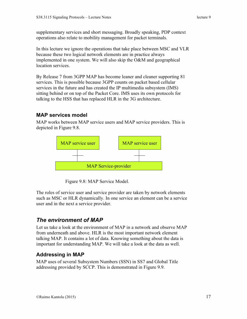
MAP services model MAP works between MAP service users and MAP service providers. This is depicted in Figure 9.8.
Raimo Kantola – S- 2007 Signaling Protocols 9 - 27
MAP works between MAP Service Users and MAP Service Providers
MAP service user MAP service user
MAP Service-provider
• MAP SUs and MAP SPs are network functions such as HLR,MSC etc.
• The roles are dynamic, i.e a node can be a user for oneoperation and a service provider for another.
Figure 9.8: MAP Service Model.
The roles of service user and service provider are taken by network elements such as MSC or HLR dynamically. In one service an element can be a service user and in the next a service provider.
The environment of MAP Let us take a look at the environment of MAP in a network and observe MAP from underneath and above. HLR is the most important network element talking MAP. It contains a lot of data. Knowing something about the data is important for understanding MAP. We will take a look at the data as well.
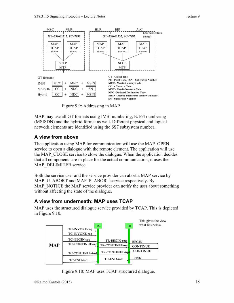
Addressing in MAP MAP uses of several Subsystem Numbers (SSN) in SS7 and Global Title addressing provided by SCCP. This is demonstrated in Figure 9.9.
Raimo Kantola – S- 2007 Signaling Protocols 9 - 39
Addressing MAP messages
MAPTCAPSSN=8
MAPTCAPSSN=7
MAPTCAPSSN=6
MAPTCAPSSN=9
MAPTCAPSSN=6
SCCPMTP
SCCPMTP
HLR EIR AuCMSC VLR
GT=358601212, PC=7896 GT=358601332, PC=7895
GT - Global TitlePC - Point Code, SSN – Subsystem NumberMCC - Mobile Country CodeCC - Country CodeMNC - Mobile Network CodeNDC - National Destination CodeMSIN - Mobile Subscriber Identity NumberSN - Subscriber Number
MCC
CC
CC
MSIN
SN
MSIN
MNC
NDC
NDC
+
+
+
+
+
+
IMSI
MSISDN
Hybrid
GT formats:
(Authentication centre)
Figure 9.9: Addressing in MAP
MAP may use all GT formats using IMSI numbering, E.164 numbering (MSISDN) and the hybrid format as well. Different physical and logical network elements are identified using the SS7 subsystem number.
A view from above The application using MAP for communication will use the MAP_OPEN service to open a dialogue with the remote element. The application will use the MAP_CLOSE service to close the dialogue. When the application decides that all components are in place for the actual communication, it uses the MAP_DELIMITER service. Both the service user and the service provider can abort a MAP service by MAP_U_ABORT and MAP_P_ABORT service respectively. By MAP_NOTICE the MAP service provider can notify the user about something without affecting the state of the dialogue.
A view from underneath: MAP uses TCAP MAP uses the structured dialogue service provided by TCAP. This is depicted in Figure 9.10.
Raimo Kantola – S- 2007 Signaling Protocols 9 - 41
Data in HLR HLR contains subscriber information including the subscriber’s location. This information is addressable using IMSI found on the SIM card. HLR also contains all kinds of service information (which services the subscriber can use). This information is addressed using MSISDN. HLR maintains a mapping from IMSI to MSISDN and vice versa. Release98 HLR database has
- location information (VLR number) - basic telecommunications services subscription information - service restrictions (e.g. roaming limitations) - supplementary service parameters - GPRS subscription data and routeing information: e.g. APN – Access
Point Name pointing to the PDN a user is allowed to connect to. The Access Point Name (APN) is similar to an URL and one APN may point to the Internet or to a particular Intranet GPRS service connects the user to.
Mobility management support in MAP Mobility management support in MAP can be classified into several categories. For example the classification can be:
• Location management • Handover MSC-MSC during a call • Authentication and security • Mobile terminal validation: IMEI - mobile equipment id queries • Subscriber management • Fault recovery (we skip this)
Note that handover needs support on many levels for example in BSSAP. For cell to cell changes in a location area MAP does not need to get involved. On this course we will however skip BSSAP.
Location Management in MAP Location management has operations for location updates for circuit switched services. The operations are depicted in Figure 9.11.
Raimo Kantola – S- 2007 Signaling Protocols 9 - 44
Location management maintains the location of the MSs in the HLR
• SendIdentification requests MS info (IMSI, authentication) from the previous VLR.
• UpdateLocation updates the new location with the accuracy of a VLR area• With PurgeMS VLR tells to HLR that MS is unreachable e.g. because of
out-of coverage condition (independent of the previous sequence).
(MSC)VLR HLR
MAP/D
UpdateLocation
CancelLocation
PurgeMS
(MSC)VLR
SendIdentification
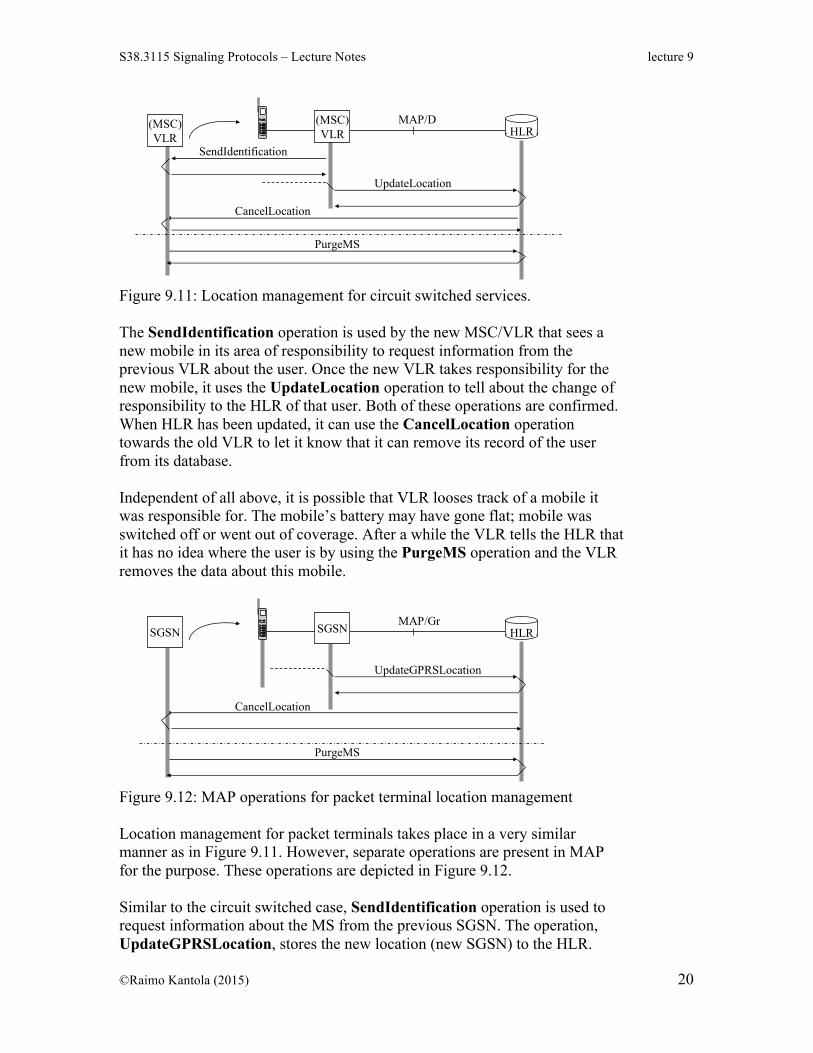
Figure 9.11: Location management for circuit switched services. The SendIdentification operation is used by the new MSC/VLR that sees a new mobile in its area of responsibility to request information from the previous VLR about the user. Once the new VLR takes responsibility for the new mobile, it uses the UpdateLocation operation to tell about the change of responsibility to the HLR of that user. Both of these operations are confirmed. When HLR has been updated, it can use the CancelLocation operation towards the old VLR to let it know that it can remove its record of the user from its database. Independent of all above, it is possible that VLR looses track of a mobile it was responsible for. The mobile’s battery may have gone flat; mobile was switched off or went out of coverage. After a while the VLR tells the HLR that it has no idea where the user is by using the PurgeMS operation and the VLR removes the data about this mobile.
Raimo Kantola – S- 2007 Signaling Protocols 9 - 45
Location management maintains the location of the GPRS MSs in the SGSN and HLR
• SendIdentification requests MS info (IMSI, authentication) from the previous SGSN.
• UpdateLocation updates the new location with the accuracy of a SGSN area• With PurgeMS SGSN tells to HLR that MS is unreachable.
SGSN HLRMAP/Gr
UpdateGPRSLocation
CancelLocation
PurgeMS
SGSN
Figure 9.12: MAP operations for packet terminal location management Location management for packet terminals takes place in a very similar manner as in Figure 9.11. However, separate operations are present in MAP for the purpose. These operations are depicted in Figure 9.12. Similar to the circuit switched case, SendIdentification operation is used to request information about the MS from the previous SGSN. The operation, UpdateGPRSLocation, stores the new location (new SGSN) to the HLR.
CancelLocation is used to remove stale data from the previous SGSN. Like before, PurgeMS is independent of the rest and is used by a SGSN that has lost track of a mobile to update the status change in the mobile’s HLR.
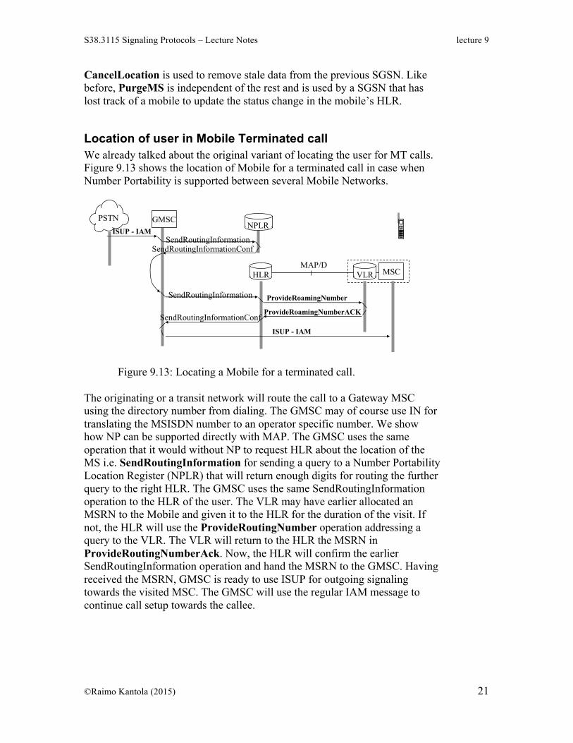
Location of user in Mobile Terminated call We already talked about the original variant of locating the user for MT calls. Figure 9.13 shows the location of Mobile for a terminated call in case when Number Portability is supported between several Mobile Networks.
Raimo Kantola – S- 2007 Signaling Protocols 9 - 47
GSM Number Portability can be implemen-ted by NP Location Register
PSTN
HLR MSCVLR
SendRoutingInformation ProvideRoamingNumber
ProvideRoamingNumberACKSendRoutingInformationConf
ISUP - IAM
MAP/D
GMSCNPLR
ISUP - IAMSendRoutingInformation
SendRoutingInformationConf
Figure 9.13: Locating a Mobile for a terminated call.
The originating or a transit network will route the call to a Gateway MSC using the directory number from dialing. The GMSC may of course use IN for translating the MSISDN number to an operator specific number. We show how NP can be supported directly with MAP. The GMSC uses the same operation that it would without NP to request HLR about the location of the MS i.e. SendRoutingInformation for sending a query to a Number Portability Location Register (NPLR) that will return enough digits for routing the further query to the right HLR. The GMSC uses the same SendRoutingInformation operation to the HLR of the user. The VLR may have earlier allocated an MSRN to the Mobile and given it to the HLR for the duration of the visit. If not, the HLR will use the ProvideRoutingNumber operation addressing a query to the VLR. The VLR will return to the HLR the MSRN in ProvideRoutingNumberAck. Now, the HLR will confirm the earlier SendRoutingInformation operation and hand the MSRN to the GMSC. Having received the MSRN, GMSC is ready to use ISUP for outgoing signaling towards the visited MSC. The GMSC will use the regular IAM message to continue call setup towards the callee.
Triangular routing in GSM Let us take a look at a call case where the MO and MT subscribers reside in a foreign network: for example two friends who are Elisa2 customers are visiting Australia. Making calls directly in the visited network with the necessary routing information queries to HLR in Elisa’s network would be the efficient thing to do. There is a problem of trust in this scenario. After the visit to Australia, the visited network operator may send a significant bill to Elisa and Elisa will charge it to its customers without really knowing whether the calls were really made. Due to this trust problem such calls are usually routed quite inefficiently through the home network. To remove such triangular routing there is even a ResumeCallHandling operation in MAP between an MSC and the Gateway MSC but this operation is rarely used.
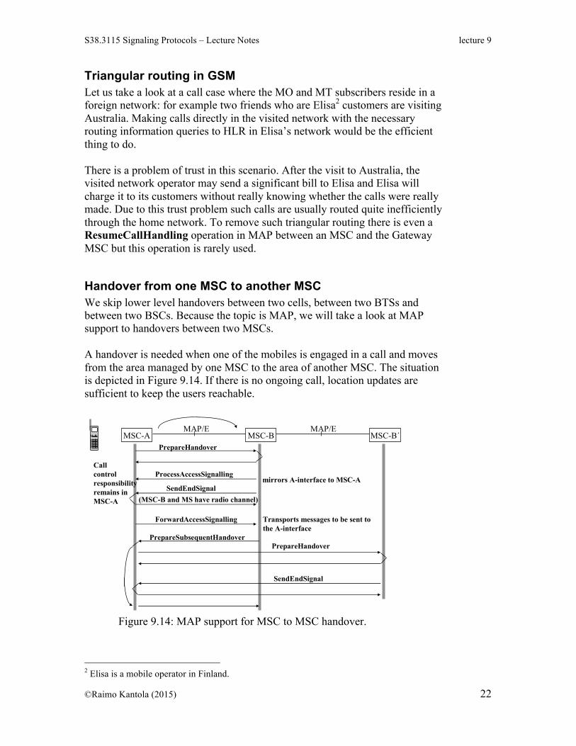
Handover from one MSC to another MSC We skip lower level handovers between two cells, between two BTSs and between two BSCs. Because the topic is MAP, we will take a look at MAP support to handovers between two MSCs. A handover is needed when one of the mobiles is engaged in a call and moves from the area managed by one MSC to the area of another MSC. The situation is depicted in Figure 9.14. If there is no ongoing call, location updates are sufficient to keep the users reachable.
Raimo Kantola – S- 2007 Signaling Protocols 9 - 49
Handover from MSC to MSC
MSC-A MSC-B MSC-B´MAP/E MAP/E
PrepareHandover
SendEndSignal(MSC-B and MS have radio channel)
Callcontrolresponsibilityremains inMSC-A
ProcessAccessSignallingmirrors A-interface to MSC-A
First of all, the principle of the MSC to MSC handover is that the original MSC always remains on the call path and becomes a so called anchor MSC for the call. The anchor MSC is marked as MSC-A in the Figure. The new MSC is marked as MSC-B. The handover starts when the anchor MSC sends the PrepareHandover operation to the new MSC. The anchor MSC has learned the identity of the new MSC from the MS that has to have two active signaling channels to cells connected to the two MSCs for a while. The new MSC starts mirroring the events of its access side interface towards the MS to the anchor MSC by sending the ProcessAccessSignaling operation. Using this operation MAP becomes the transport protocol for access signaling! When the new MSC is happy about the quality of its connection with the MS, it will use the SendEndSignal operation to let the anchor (or the previous MSC) know that it may release the radio access resources that were previously used by the MS. This is a confirmed operation. When call control in the anchor MSC creates a message to be sent to the MS, it uses MAP as the transport protocol with ForwardAccessSignaling operation to the new MSC that has a radio link to the MS. If MSC-B’s connection is getting weaker and the MS initiates a handover to MSC-B’, MSC-B will let the anchor MSC know about this by PrepareSubsequentHandover operation. The rest of the subsequent-handover takes place between MSC-B’ and the anchor MSC. The operation is similar to the previous handover between MSC-B and the anchor MSC. The SendEndSignal operation needs to be routed to the previous MSC-B. The anchor MSC finalizes the operation by sending the confirmation of the PrepareSubsequentHandover to the previous MSC-B.
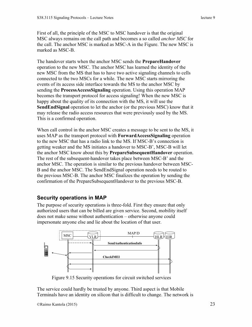
Security operations in MAP The purpose of security operations is three-fold. First they ensure that only authorized users that can be billed are given service. Second, mobility itself does not make sense without authentication – otherwise anyone could impersonate anyone else and lie about the location of that user.
Raimo Kantola – S- 2007 Signaling Protocols 9 - 50
Security operations ensure that only authorized subscribers can use the service
HLRMSC VLRMAP/D
SendAuthenticationInfo
EIR
CheckIMEI
Black list of suspect stolen phones ensuresthat stolen equipment can not be used forlong
Figure 9.15 Security operations for circuit switched services
The service could hardly be trusted by anyone. Third aspect is that Mobile Terminals have an identity on silicon that is difficult to change. The network is
able to check this identity in order to track stolen MSs and remove them from the network. The two operations in this category are depicted in Figure 9.15. The SendAuthenticationInfo operation is between the VLR and the HLR (AC). In actual use it will be interleaved for example with location management operations. Such interleaving is for the application using MAP. The CheckIMEI operation is sent by the VLR to the EIR. EIR will check the Equipment Identity against the blacklisted and grey listed phones. There is a global register that is distributed off-line among all GSM operators. Similarly as the MSC/VLR uses the above operations to authenticate the user and to validate the user’s equipment, SGSN can use the same operations for packet switched services.
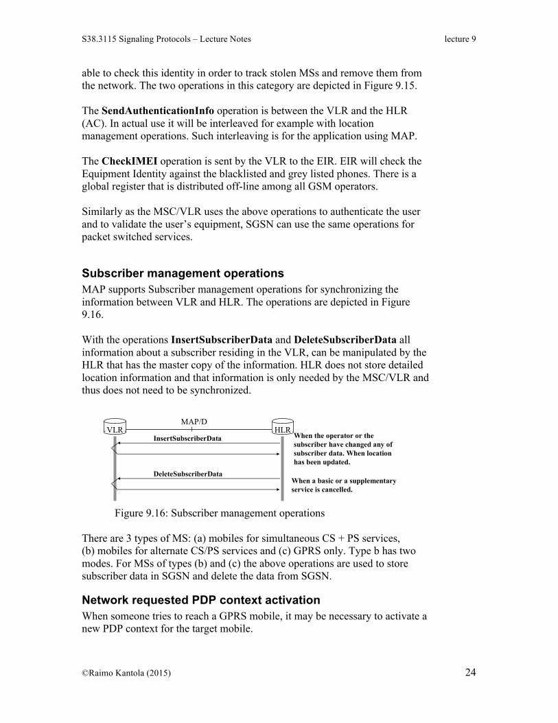
Subscriber management operations MAP supports Subscriber management operations for synchronizing the information between VLR and HLR. The operations are depicted in Figure 9.16. With the operations InsertSubscriberData and DeleteSubscriberData all information about a subscriber residing in the VLR, can be manipulated by the HLR that has the master copy of the information. HLR does not store detailed location information and that information is only needed by the MSC/VLR and thus does not need to be synchronized.
Raimo Kantola – S- 2007 Signaling Protocols 9 - 53
Subscriber management takes care of the subscriber data in the VLR
HLRVLRMAP/D
InsertSubscriberData When the operator or the subscriber have changed any ofsubscriber data. When locationhas been updated.
DeleteSubscriberDataWhen a basic or a supplementaryservice is cancelled.
With these operations all information residing in the VLR, can be manipulated,when the HLR has the master copy of the information. (HLR does not have somedetailed location info…)
Figure 9.16: Subscriber management operations
There are 3 types of MS: (a) mobiles for simultaneous CS + PS services, (b) mobiles for alternate CS/PS services and (c) GPRS only. Type b has two modes. For MSs of types (b) and (c) the above operations are used to store subscriber data in SGSN and delete the data from SGSN.
Network requested PDP context activation When someone tries to reach a GPRS mobile, it may be necessary to activate a new PDP context for the target mobile.
To achieve this, a GGSN may use the SendRoutingInfoforGPRS operation to HLR to get an address for the SGSN. After that pushing packets to the mobile becomes possible (this leaves it open how the MS gets its IP address and how that address is delivered to the originator of the communication). Having learned about an active GPRS terminal HLR may also use the NoteMSPresentforGPRS operation to GGSN to let the GGSN know that the terminal is available for packet services.
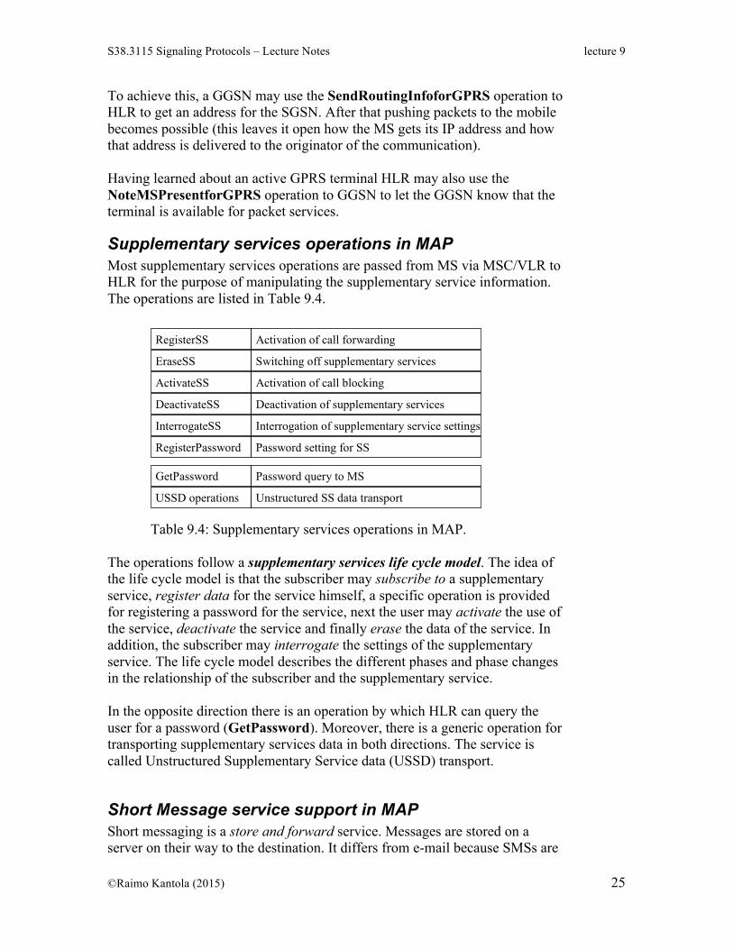
Supplementary services operations in MAP Most supplementary services operations are passed from MS via MSC/VLR to HLR for the purpose of manipulating the supplementary service information. The operations are listed in Table 9.4.
Raimo Kantola – S- 2007 Signaling Protocols 9 - 56
Supplementary service operations are passed from MS via MSC/VLR to HLR
RegisterSS Activation of call forwarding
MS --> MSC/VLR --> HLR
ActivateSS Activation of call blocking
EraseSS Switching off supplementary services
DeactivateSS Deactivation of supplementary services
InterrogateSS Interrogation of supplementary service settings
RegisterPassword Password setting for SS
GetPassword Password query to MS
USSD operations Unstructured SS data transportEvents, such as activation, registration, interrogation, deactivation etc come from SS lifecycle model.
Table 9.4: Supplementary services operations in MAP.
The operations follow a supplementary services life cycle model. The idea of the life cycle model is that the subscriber may subscribe to a supplementary service, register data for the service himself, a specific operation is provided for registering a password for the service, next the user may activate the use of the service, deactivate the service and finally erase the data of the service. In addition, the subscriber may interrogate the settings of the supplementary service. The life cycle model describes the different phases and phase changes in the relationship of the subscriber and the supplementary service. In the opposite direction there is an operation by which HLR can query the user for a password (GetPassword). Moreover, there is a generic operation for transporting supplementary services data in both directions. The service is called Unstructured Supplementary Service data (USSD) transport.
Short Message service support in MAP Short messaging is a store and forward service. Messages are stored on a server on their way to the destination. It differs from e-mail because SMSs are
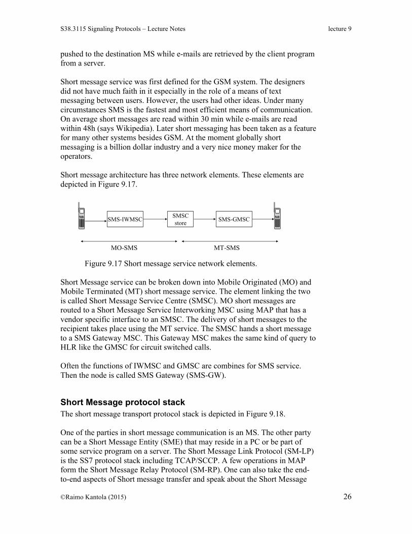
pushed to the destination MS while e-mails are retrieved by the client program from a server. Short message service was first defined for the GSM system. The designers did not have much faith in it especially in the role of a means of text messaging between users. However, the users had other ideas. Under many circumstances SMS is the fastest and most efficient means of communication. On average short messages are read within 30 min while e-mails are read within 48h (says Wikipedia). Later short messaging has been taken as a feature for many other systems besides GSM. At the moment globally short messaging is a billion dollar industry and a very nice money maker for the operators. Short message architecture has three network elements. These elements are depicted in Figure 9.17.
Raimo Kantola – S- 2007 Signaling Protocols 9 - 57
Short Message Service
SMSCstoreSMS-IWMSC SMS-GMSC
MO-SMS MT-SMS
SMSC - Short Message Service Center (or SC - Service Center) SMS-GMSC - Short message Gateway MSC, issuer of routing information query to
HLR in MT-SMSSMS-IWMSC - Short message Inter-working MSC, routing MSC in MO-SMS serviceSMS-GW = SMS-IWMSC + SMS-GMSC
MO - Mobile OriginatedMT - Mobile Terminated
SMSC - HLR operations:- MS short message buffer full- MS reachability- successful delivery of message
Figure 9.17 Short message service network elements.
Short Message service can be broken down into Mobile Originated (MO) and Mobile Terminated (MT) short message service. The element linking the two is called Short Message Service Centre (SMSC). MO short messages are routed to a Short Message Service Interworking MSC using MAP that has a vendor specific interface to an SMSC. The delivery of short messages to the recipient takes place using the MT service. The SMSC hands a short message to a SMS Gateway MSC. This Gateway MSC makes the same kind of query to HLR like the GMSC for circuit switched calls. Often the functions of IWMSC and GMSC are combines for SMS service. Then the node is called SMS Gateway (SMS-GW).
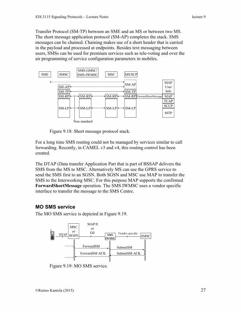
Short Message protocol stack The short message transport protocol stack is depicted in Figure 9.18. One of the parties in short message communication is an MS. The other party can be a Short Message Entity (SME) that may reside in a PC or be part of some service program on a server. The Short Message Link Protocol (SM-LP) is the SS7 protocol stack including TCAP/SCCP. A few operations in MAP form the Short Message Relay Protocol (SM-RP). One can also take the end-to-end aspects of Short message transfer and speak about the Short Message
Transfer Protocol (SM-TP) between an SME and an MS or between two MS. The short message application protocol (SM-AP) completes the stack. SMS messages can be chained. Chaining makes use of a short header that is carried in the payload and processed at endpoints. Besides text messaging between users, SMSs can be used for premium services such as tele-voting and over the air programming of service configuration parameters in mobiles.
Raimo Kantola – S- 2007 Signaling Protocols 9 - 58
Short message transport protocol stack
MTP
MAP
MAPUserInfo
TCAPSCCP
SME SMSCSMS-GMSC/SMS-IWMSC MSC MS/SCP
SM-LP
SM-RP
SM-APSM-TP
SM-LP
SM-RP
SM-LP
SM-RP
SM-LP
SM-RP
SM-AP
SM-TP
SME - Short Message Entity (may reside e.g. in a computer)SM-LP - Short Message Link Protocol SM-RP - Short Message Relay ProtocolSM-TP - Short Message Transfer ProtocolSM-AP - Short Message Application Protocol
ForwardShortMessage
Non standard
Figure 9.18: Short message protocol stack. For a long time SMS routing could not be managed by services similar to call forwarding. Recently, in CAMEL v3 and v4, this routing control has been created. The DTAP (Data transfer Application Part that is part of BSSAP delivers the SMS from the MS to MSC. Alternatively MS can use the GPRS service to send the SMS first to an SGSN. Both SGSN and MSC use MAP to transfer the SMS to the Interworking MSC. For this purpose MAP supports the confirmed ForwardShortMessage operation. The SMS IWMSC uses a vendor specific interface to transfer the message to the SMS Centre.
MO SMS service The MO SMS service is depicted in Figure 9.19.
Raimo Kantola – S- 2007 Signaling Protocols 9 - 59
Messages in MO-SMS serviceMSC
orSGSN SMSCSMS-
IWMSC
ForwardSM
DTAP
MAP/Eor
Gd Vendor specific
SubmitSM
SubmitSM ACKForwardSM ACK
Traditionally serving MSC sends short messages to the SMS Interworking MSC.Alternatively, GPRS side can do the same: SGSN sends SMS instead of sMSC.
DTAP is part of BSSAP (Data Transfer Application Part...), BSSAP = A-interface orBase Station Subsystem Application Part
The MO service makes use of a routable telephone number of the IW MSC configured in the MS both on MAP and SCCP levels. The MSISDN number of the sender and destination are carried in the MAP protocol.
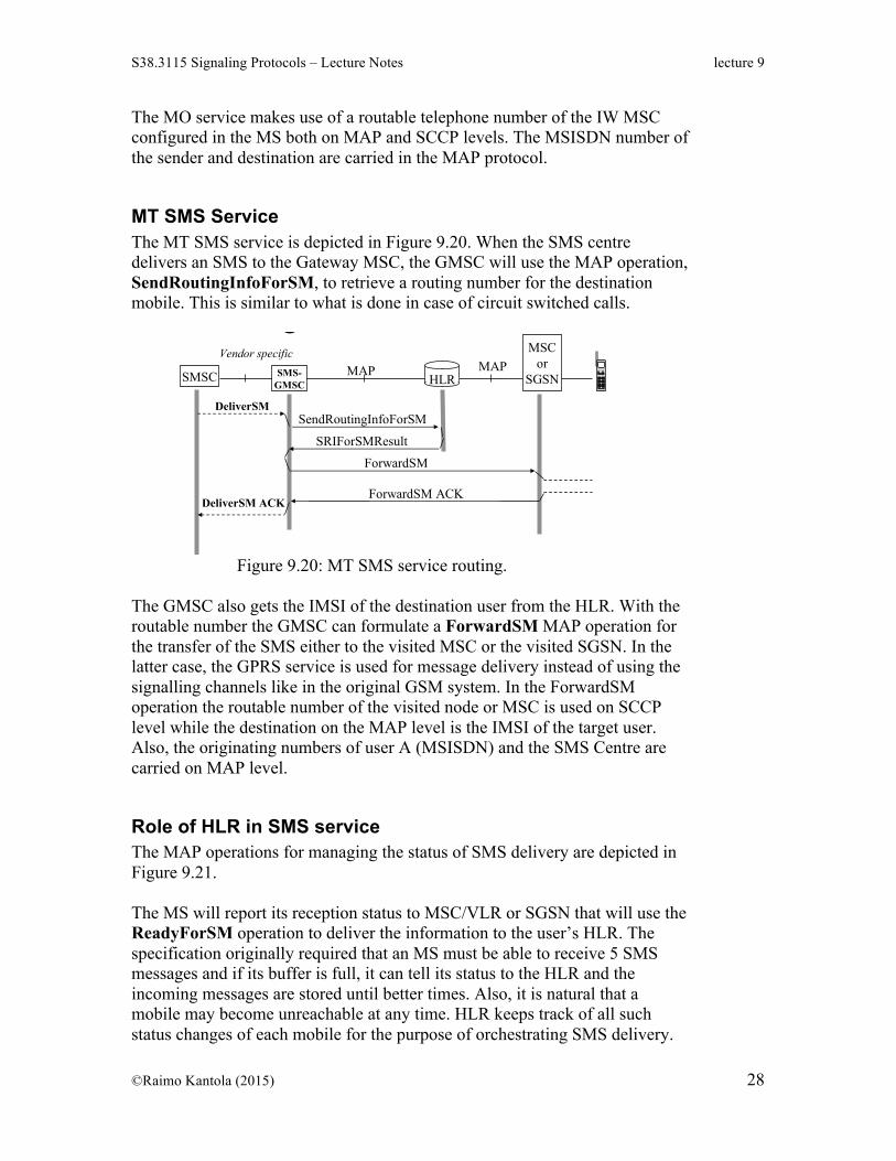
MT SMS Service The MT SMS service is depicted in Figure 9.20. When the SMS centre delivers an SMS to the Gateway MSC, the GMSC will use the MAP operation, SendRoutingInfoForSM, to retrieve a routing number for the destination mobile. This is similar to what is done in case of circuit switched calls.
Raimo Kantola – S- 2007 Signaling Protocols 9 - 60
Messages in MT-SMS service
HLRSMSC SMS-GMSC
SendRoutingInfoForSMDeliverSM
Vendor specific
SRIForSMResult
MSCor
SGSNMAP MAP
ForwardSM
ForwardSM ACKDeliverSM ACK
The SMS can be delivered either by a serving MSC orthe SGSN thru GPRS service.NB: When SMSs are carried over MAP, they may create a significantload on the underlaying CSS7 signaling network!
Figure 9.20: MT SMS service routing.
The GMSC also gets the IMSI of the destination user from the HLR. With the routable number the GMSC can formulate a ForwardSM MAP operation for the transfer of the SMS either to the visited MSC or the visited SGSN. In the latter case, the GPRS service is used for message delivery instead of using the signalling channels like in the original GSM system. In the ForwardSM operation the routable number of the visited node or MSC is used on SCCP level while the destination on the MAP level is the IMSI of the target user. Also, the originating numbers of user A (MSISDN) and the SMS Centre are carried on MAP level.
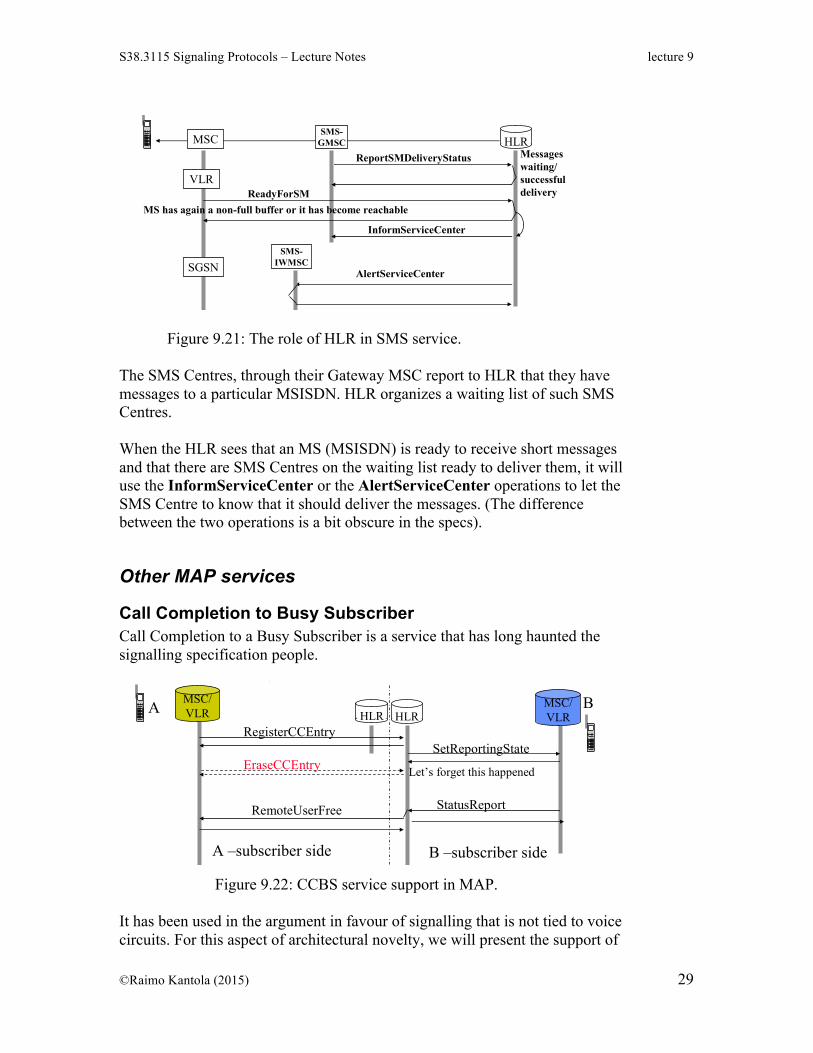
Role of HLR in SMS service The MAP operations for managing the status of SMS delivery are depicted in Figure 9.21. The MS will report its reception status to MSC/VLR or SGSN that will use the ReadyForSM operation to deliver the information to the user’s HLR. The specification originally required that an MS must be able to receive 5 SMS messages and if its buffer is full, it can tell its status to the HLR and the incoming messages are stored until better times. Also, it is natural that a mobile may become unreachable at any time. HLR keeps track of all such status changes of each mobile for the purpose of orchestrating SMS delivery.
Raimo Kantola – S- 2007 Signaling Protocols 9 - 61
Status information is kept in HLRHLRMSC
SMS-GMSC
AlertServiceCenter
InformServiceCenter
ReadyForSM
ReportSMDeliveryStatus
VLR
SMS-IWMSC
Messageswaiting/successfuldelivery
MS has again a non-full buffer or it has become reachable
• SM destination subscriber can tell the network, that its SM buffer is full or thatthe subscriber has become unreachable. HLR stores the status.
• When Status is good for receiving, VLR or SGSN gets the info and sends it to HLR.
• HLR informs those SMSCs that have reported themselves onto the waiting list.
• Interpretation: IWMSC to SMSC and GWMSC to SMSC interfaces are vendor specific.Optionally either one of the MSCs can report itself onto the Waiting list in HLR.
SGSN
Figure 9.21: The role of HLR in SMS service. The SMS Centres, through their Gateway MSC report to HLR that they have messages to a particular MSISDN. HLR organizes a waiting list of such SMS Centres. When the HLR sees that an MS (MSISDN) is ready to receive short messages and that there are SMS Centres on the waiting list ready to deliver them, it will use the InformServiceCenter or the AlertServiceCenter operations to let the SMS Centre to know that it should deliver the messages. (The difference between the two operations is a bit obscure in the specs).
Other MAP services
Call Completion to Busy Subscriber Call Completion to a Busy Subscriber is a service that has long haunted the signalling specification people.
Raimo Kantola – S- 2007 Signaling Protocols 9 - 63
MSC/VLR
GSM supports Call Completion to Busy Subscriber (CCBS)
HLR HLRA B
SetReportingState
StatusReportRemoteUserFree
RegisterCCEntry
EraseCCEntry Let’s forget this happened
A –subscriber side B –subscriber side
MSC/VLR
A calls when B is busy. A registers that he/she wants to know when B becomes free.HLR sets the reporting state to B’s VLR. When B becomes free, new status isreported to HLR. HLR tells A’s VLR/MSC that B is now free and call can be comp-leted so that A pays normally. There is a CCBS protocol (HLR-HLR) also …
Figure 9.22: CCBS service support in MAP.
It has been used in the argument in favour of signalling that is not tied to voice circuits. For this aspect of architectural novelty, we will present the support of
CCBS in MAP. The MAP operations that are needed by this supplementary service are depicted in Figure 9.22. The caller A notices that the callee B is busy and activates the CCBS service. The visited MSC uses the RegisterCCEntry MAP operation to initiate status monitoring for B in the callee’s HLR. Naturally, caller A can always cancel the CCBS service. For this purpose the visited MSC uses the EraseCCEntry operation to the callee’s HLR. The callee’s HLR will need to set the status monitoring in the visited MSC of the callee. HLR uses the SetReportingState MAP operation to request the vMSC to tell it when callee becomes free. We will later see that the SIP protocol has generalized this mechanism for numerous service use cases. In SIP the operations are called publish and subscribe. The vMSC uses the StatusReport MAP operation to tell the HLR that the user has become free. The HLR delivers this information to the originating vMSC using the RemoteUserFree MAP operation. Now, call establishment can be initiated by the caller’s vMSC by alerting the caller and using ISUP to establish a call towards the callee B. Call charging will be normal, i.e. the caller will pay. (Naturally, we could have just stored the reporting state in callee’s vMSC and established the call in the opposite direction but this would lead to B paying for the call which is unacceptable). Note that during the whole flow of operations in Figure 9.22, there was no voice circuit between the visited MSCs of the two involved subscribers.
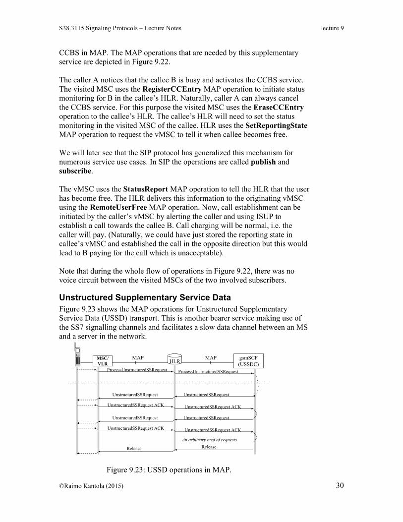
Unstructured Supplementary Service Data Figure 9.23 shows the MAP operations for Unstructured Supplementary Service Data (USSD) transport. This is another bearer service making use of the SS7 signalling channels and facilitates a slow data channel between an MS and a server in the network.
Raimo Kantola – S- 2007 Signaling Protocols 9 - 66
USSD dialogue can be initiated by MS (pull) or by a server (push)
The service can be used in the pull mode, i.e. MS initiates the data transfer or in the push mode where the server initiates the data transfer. When discussing IP networks we will see the difficulties related to push services. USSD using signalling channels that are always-on is one solution how push services to mobiles can be implemented.
Summary of mobility management and MAP We discussed the many complementary and competing methods how the hard problem of mobility management of cellular users has been solved. First, dialled digits are used for locating the Home Location Register of the called user. The MSC currently in charge of the user assigns a Mobile Services Routing Number to the visiting user and tells this number to the HLR. This number can be used to route calls from anywhere in the global telephone network to a mobile and even to a roaming user. Second, the cell sizes and the placement of cells are designed in such a way that capacity requirements are met and that the need of a mobile for changing its cell is minimized. Third, location updates are organised in a hierarchical manner. The network may trace the location of an active user with the accuracy of a single cell while it traces inactive users with less accuracy. The VLR in the visited network does not tell HLR every move the mobile makes, etc. As a result of all these design choices, scalable mobility management architecture has been created. It can handle Billions users with ease. It has even been possible to add national number portability into the architecture. There are differences in the details of mobility management for packet services and circuit switched services. These differences optimize the performance of the mobility management for the packet and circuit switched services. MAP is the protocol that adds the mobility management capability to the mobile core network for circuit and packet switched services. MAP also supports many mobile specific supplementary services and carries short messages over the SS7 infrastructure. MAP belongs to the family of SS7 protocols and it makes use of the complete underlying SS7 protocol stack (MTP, SCCP and TCAP with all addressing modes that are available).