37
Lecture Note on Network Processors
| Date post: | 25-Dec-2015 |
| Category: |
Documents |
| Upload: | russell-dean |
| View: | 219 times |
| Download: | 2 times |
Lecture Note on Network Processors
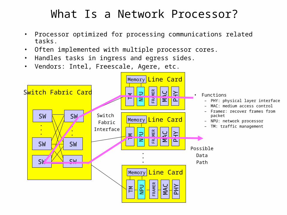
What Is a Network Processor?
• Processor optimized for processing communications related tasks.• Often implemented with multiple processor cores.• Handles tasks in ingress and egress sides.• Vendors: Intel, Freescale, Agere, etc.
• Functions– PHY: physical layer interface– MAC: medium access control– Framer: recover frames from packet– NPU: network processor– TM: traffic management
Switch
Fabric
Interface
FR
AM
ER
MA
C
PH
Y
NP
U
TM
Line CardMemory
FR
AM
ER
MA
C
PH
Y
NP
U
TM
Line CardMemory
FR
AM
ER
MA
C
PH
Y
NP
U
TM
Line CardMemory
• • •
Switch Fabric Card
SWSW
SW
SW
SW
SW
• • •
• • •
Possible
Data
Path

Example: Intel IXP Network Processors
• Microengines– RISC processors optimized for
packet processing– Hardware support for multi-
threading– Fast path
• Embedded StrongARM/Xscale – Runs embedded OS and handles
exception tasks – Slow path, Control planeM
E 1
ME
2
ME
n
StrongARM
SR
AM
DR
AM
Switch Fabric
Interface
ControlProcessor
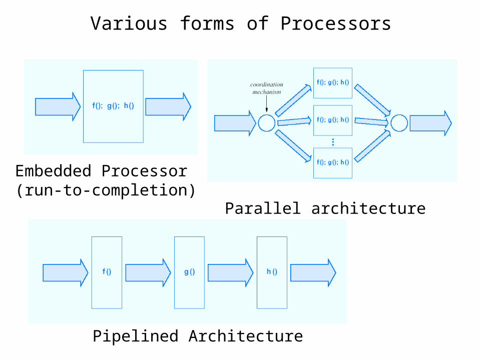
Various forms of Processors
Embedded Processor (run-to-completion)
Parallel architecture
Pipelined Architecture

Software Architectures

Division of Functions

Packet Flow Through the Hierarchy
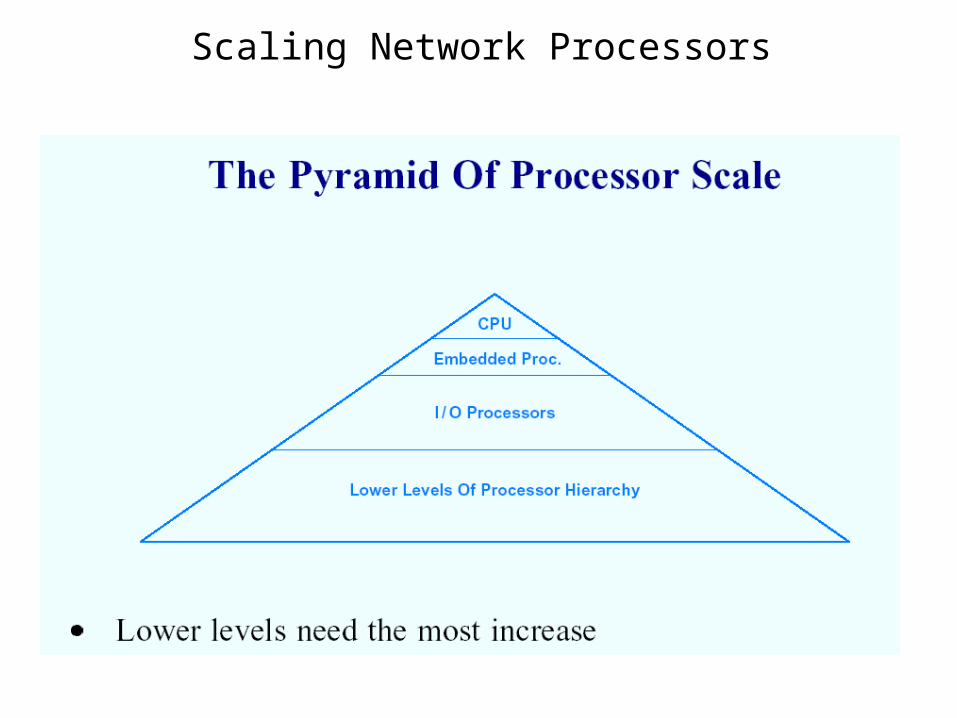
Scaling Network Processors
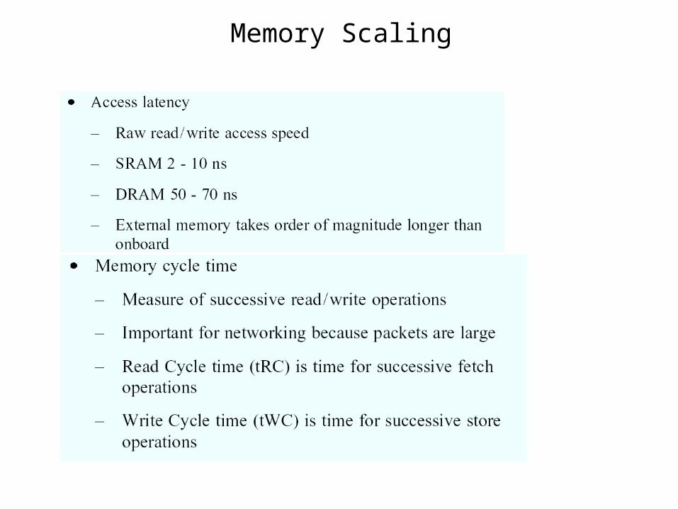
Memory Scaling

Memory Scaling (continued)
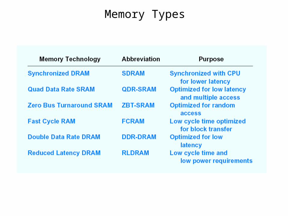
Memory Types
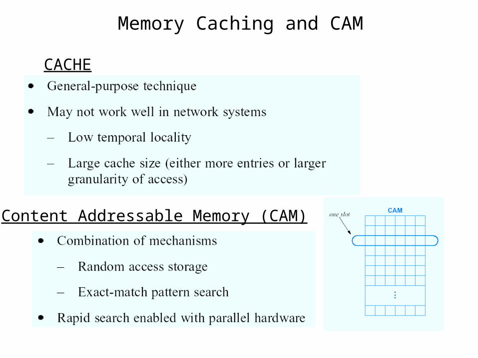
Memory Caching and CAM
CACHE
Content Addressable Memory (CAM)

CAM and Ternary CAM
CAM Operation:
Ternary CAM (T-CAM):

Ternary CAMs
10.0.0.0 R110.1.0.0 R210.1.1.0 R310.1.3.0 R4
255.0.0.0255.255.0.0255.255.255.0255.255.255.0255.255.255.25510.1.3.1 R4
Value Mask
Priority Encoder
Next Hop
Associative Memory
Using T-CAMs for Classification:
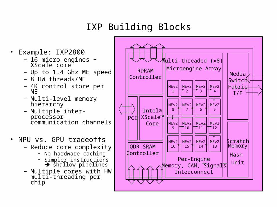
IXP Building Blocks
• Example: IXP2800– 16 micro-engines + XScale core– Up to 1.4 Ghz ME speed– 8 HW threads/ME– 4K control store per ME– Multi-level memory hierarchy– Multiple inter-processor
communication channels
• NPU vs. GPU tradeoffs– Reduce core complexity
• No hardware caching• Simpler instructions shallow
pipelines– Multiple cores with HW multi-
threading per chip
MEv210
MEv211
MEv212
MEv215
MEv214
MEv213
MEv29
MEv216
MEv22
MEv23
MEv24
MEv27
MEv26
MEv25
MEv21
MEv28
RDRAMController
Intel®XScale™
Core
MediaSwitchFabric
I/F
PCI
QDR SRAM Controller
ScratchMemory
Hash
Unit
Multi-threaded (x8)
Microengine Array
Per-EngineMemory, CAM, Signals
Interconnect
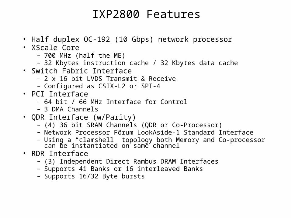
IXP2800 Features
• Half duplex OC-192 (10 Gbps) network processor• XScale Core
– 700 MHz (half the ME) – 32 Kbytes instruction cache / 32 Kbytes data cache
• Switch Fabric Interface– 2 x 16 bit LVDS Transmit & Receive– Configured as CSIX-L2 or SPI-4
• PCI Interface– 64 bit / 66 MHz Interface for Control– 3 DMA Channels
• QDR Interface (w/Parity)– (4) 36 bit SRAM Channels (QDR or Co-Processor)– Network Processor Forum LookAside-1 Standard Interface– Using a “clamshell” topology both Memory and Co-processor can be instantiated on
same channel• RDR Interface
– (3) Independent Direct Rambus DRAM Interfaces– Supports 4i Banks or 16 interleaved Banks– Supports 16/32 Byte bursts
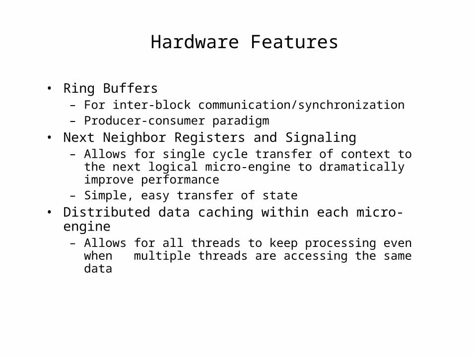
Hardware Features
• Ring Buffers– For inter-block communication/synchronization– Producer-consumer paradigm
• Next Neighbor Registers and Signaling– Allows for single cycle transfer of context to the next logical micro-
engine to dramatically improve performance– Simple, easy transfer of state
• Distributed data caching within each micro-engine– Allows for all threads to keep processing even when multiple threads
are accessing the same data
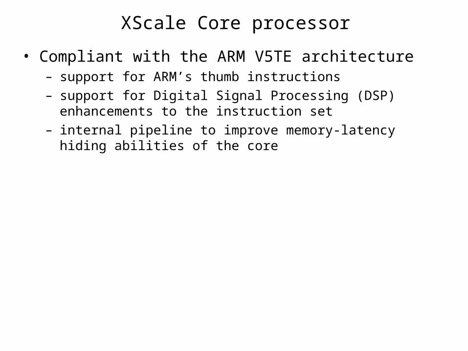
XScale Core processor
• Compliant with the ARM V5TE architecture – support for ARM’s thumb instructions
– support for Digital Signal Processing (DSP) enhancements to the instruction set
– internal pipeline to improve memory-latency hiding abilities of the core

Microengine RISC processors
• IXP 2800 has 16 microengines, organized into 4 clusters (4 MEs per cluster)
• ME instruction set specifically tuned for processing network data• 40-bit x 4K control store• Six-stage pipeline in an instruction
– On an average takes one cycle to execute
• Each ME has eight hardware-assisted threads of execution– can be configured to use either all eight threads or only four threads
• Non-preemptive thread arbiter swaps between threads in round-robin order

Microengine
time
0
Microenginethreadn
1
2
3
4
5
6
7
Executingcode
Waiting forsignal
Ready toexecute
t1 t2t3
Why Multi-Threading?
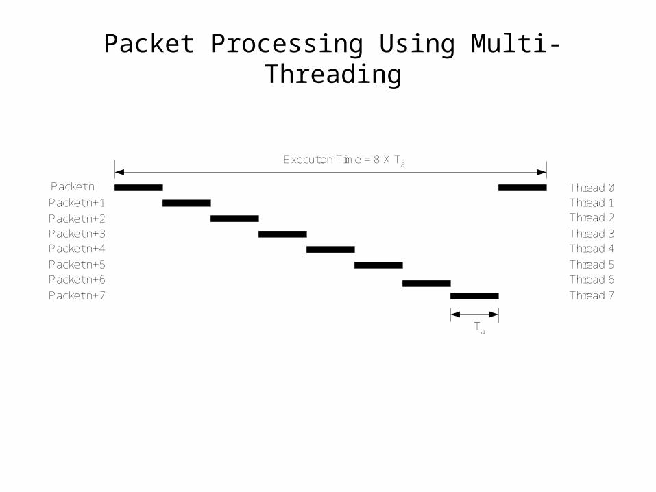
Packet Processing Using Multi-Threading
Thread 0
Thread 7
Thread 6Thread 5
Thread 4Thread 3
Thread 2Thread 1
Packet n
Packet n+7
Packet n+6Packet n+5
Packet n+4Packet n+3Packet n+2
Packet n+1
Execution Time = 8 X Ta
Ta

Types of Memory
Type of Memory
Width
(bytes)
Size
(bytes)
Latency (cycles)
Local to ME 4 2560 3
On-chip Scratch 4 16K 60
SRAM 4 256M 150
DRAM 8 2G 300
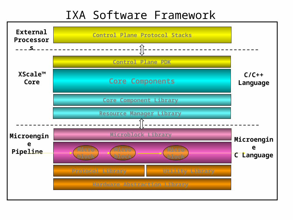
IXA Software Framework
Resource Manager Library
Control Plane PDK
Control Plane Protocol Stacks
Core Components
MicroenginePipeline
XScale™Core
Microblock
Microblock
Microblock
Microblock Library
Utility LibraryProtocol Library
ExternalProcessors
Hardware Abstraction Library
MicroengineC Language
C/C++ Language
Core Component Library
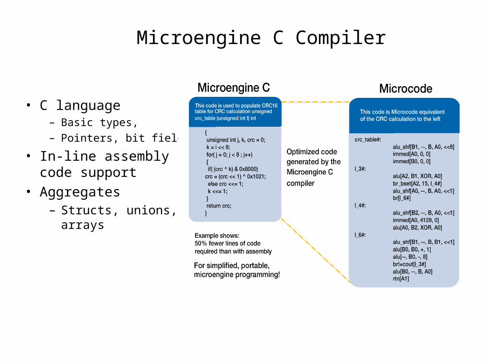
• C language– Basic types,
– Pointers, bit fields
• In-line assembly code support
• Aggregates– Structs, unions, arrays
Microengine C Compiler

What Is Microblock?
• Data plane packet processing on the microengines is divided into logical functions called microblocks
• Example – 5-Tuple Classification, IPv4 Forwarding, NAT
• Several microblocks running on a microengine thread can be combined into a microblock group.
• Microblocks can send and receive packets to/from an associated Xscale core component.

Core Components and Microblocks
XScale™ Core
Micro-engines
User-written code
Microblock Library
Intel/3rd party blocks
Microblock
Microblock Library
Microblock Microblock
Core Component
CoreComponent
Core Component
CoreLibraries
Core Component Library
Resource Manager Library

Applications of Network Processors
• Packet processing application– Routing/switching– VPN– DSLAM– Multi-service switch– Storage– Content processing– Security– RMON
• Research platform– Experiment with new algorithms, protocols
• Training tool– Understand architectural issues– Gain hands-on experience withy networking systems
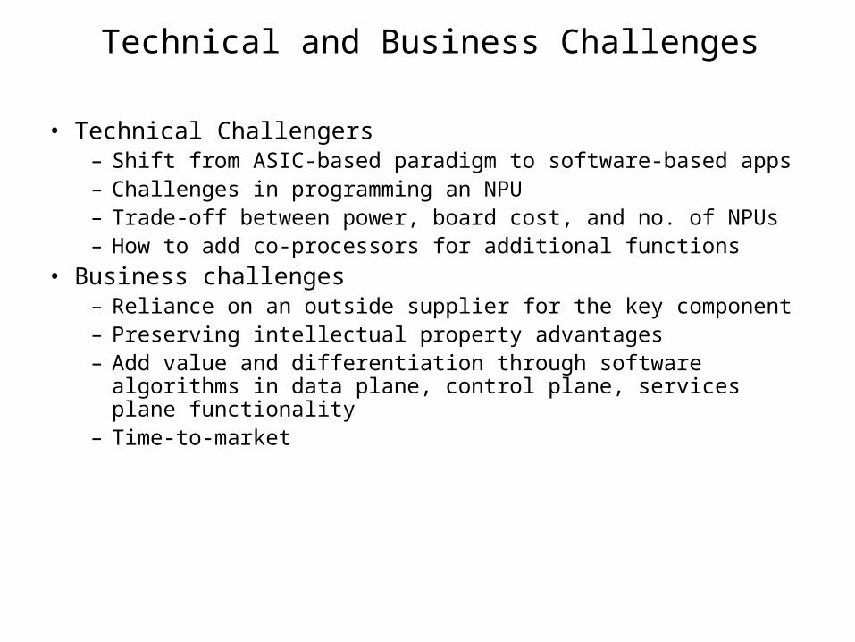
Technical and Business Challenges
• Technical Challengers– Shift from ASIC-based paradigm to software-based apps– Challenges in programming an NPU– Trade-off between power, board cost, and no. of NPUs– How to add co-processors for additional functions
• Business challenges– Reliance on an outside supplier for the key component– Preserving intellectual property advantages– Add value and differentiation through software algorithms in data plane, control
plane, services plane functionality– Time-to-market

Challenges in Terabit Class Switch Design
• Power• Packaging• Internal Round Trip• Chip Speed Up• Multicast• Packet Size
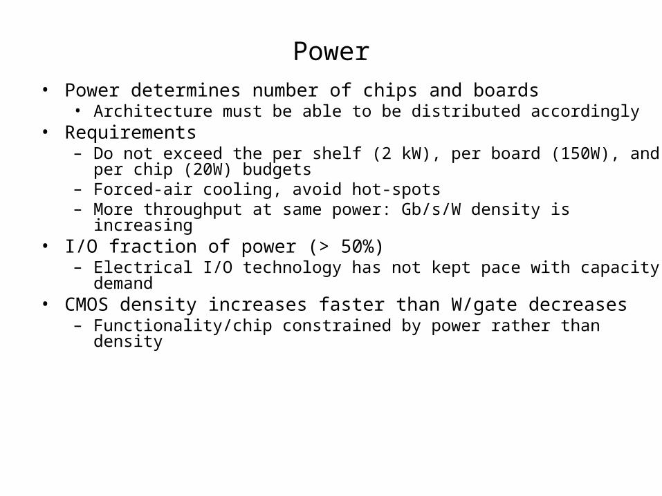
Power• Power determines number of chips and boards
• Architecture must be able to be distributed accordingly• Requirements
– Do not exceed the per shelf (2 kW), per board (150W), and per chip (20W) budgets– Forced-air cooling, avoid hot-spots– More throughput at same power: Gb/s/W density is increasing
• I/O fraction of power (> 50%)– Electrical I/O technology has not kept pace with capacity demand
• CMOS density increases faster than W/gate decreases– Functionality/chip constrained by power rather than density
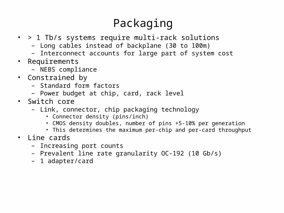
Packaging• > 1 Tb/s systems require multi-rack solutions
– Long cables instead of backplane (30 to 100m)– Interconnect accounts for large part of system cost
• Requirements– NEBS compliance
• Constrained by– Standard form factors– Power budget at chip, card, rack level
• Switch core– Link, connector, chip packaging technology
• Connector density (pins/inch)• CMOS density doubles, number of pins +5-10% per generation• This determines the maximum per-chip and per-card throughput
• Line cards– Increasing port counts– Prevalent line rate granularity OC-192 (10 Gb/s)– 1 adapter/card
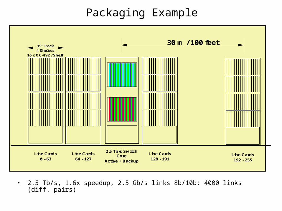
Packaging Example
2.5 Tb/s Switch Core
Active + Backup
Line Cards64 - 127
Line Cards128 - 191
Line Cards0 - 63
19" Rack4 Shelves
16 x OC-192 / Shelf
Line Cards192 - 255
30 m / 100 feet
• 2.5 Tb/s, 1.6x speedup, 2.5 Gb/s links 8b/10b: 4000 links (diff. pairs)
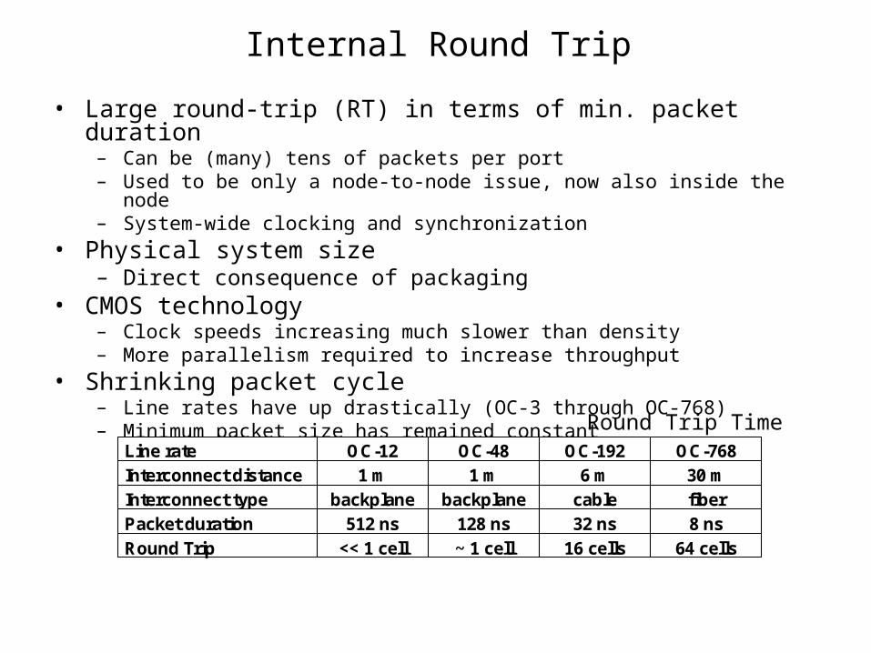
Internal Round Trip
• Large round-trip (RT) in terms of min. packet duration– Can be (many) tens of packets per port– Used to be only a node-to-node issue, now also inside the node– System-wide clocking and synchronization
• Physical system size– Direct consequence of packaging
• CMOS technology– Clock speeds increasing much slower than density– More parallelism required to increase throughput
• Shrinking packet cycle– Line rates have up drastically (OC-3 through OC-768)– Minimum packet size has remained constant
Line rate OC-12 OC-48 OC-192 OC-768Interconnect distance 1 m 1 m 6 m 30 mInterconnect type backplane backplane cable fiber
Packet duration 512 ns 128 ns 32 ns 8 ns
Round Trip << 1 cell ~ 1 cell 16 cells 64 cells
Round Trip Time

Data Flow
switch core
networkprocessor
ingress buffer
egress buffer
data
ingress FC
data
egress FC
input line 1
output line 1
OC
-x i
tf
networkprocessor
ingress buffer
egress buffer
input line 1
output line 1
OC
-x i
tf
switch fabricinterface chips
switch fabricline card 1
line card N
iRT
eRT
• Consequences– Performance impact
– All buffers must be scaled by round trip time
– Fabric-internal flow control becomes an important issue
iRT
eRT

Chip Speed Up
• Switch core speed-up is very costly– Bandwidth is a scarce resource: COST and POWER – Core buffers must run faster– Core scheduler must run faster– SAR overhead reduction
• Variable-length packet switching: hard to implement, but may be more cost-effective– Performance: does the gain in performance justify the increase in cost and power?
• Depends on application• Low Internet utilization
• Requirements– Industry standard 2x speed-up
• Three flavors– Utilization: compensate SAR overhead– Performance: compensate scheduling inefficiencies– OQ speed-up: memory access time
speed-up

Multicast
• Multicast– Expensive– Often disabled in the field
• Requirements– Full multicast support
• Many multicast groups, full link utilization, no blocking, QoS
• Complicates everything– Buffering, queuing, scheduling, flow control, QoS

Packet Size
• Dealing with packet size– Aggregation techniques
• Burst, envelope, container switching, “packing”
– Single-stage, multi-path switches• Parallel packet switch
• Requirements– Support very short packets (32-64B)
• 40B @ OC-768 = 8 ns
• Short packet duration– Determines speed of control section
• Queues and schedulers
– Implies longer RT– Wider data paths


