1 LECTURE NOTES ON ENGINEERING MECHANICS B. Tech III Semester (R-18) Prepared By Dr. Ch. Sandeep Associate Professor V. Prasanna Assistant Professor MECHANICAL ENGINEERING INSTITUTE OF AERONAUTICAL ENGINEERING (Autonomous) Dundigal, Hyderabad - 500 043
Transcript
1
LECTURE NOTESON
ENGINEERING MECHANICS
B. Tech III Semester (R-18)
Prepared By
Dr. Ch. SandeepAssociate Professor
V. PrasannaAssistant Professor
MECHANICAL ENGINEERING
INSTITUTE OF AERONAUTICAL ENGINEERING(Autonomous)
Dundigal, Hyderabad - 500 043
2
ENGINEERING MECHANICS
III Semester: MECourse Code Category Hours / Week Credits Maximum Marks
COURSE OBJECTIVES:The course should enable the students to:
I. Students should develop the ability to work comfortably with basic engineering mechanics concepts required for analyzing static structures.
II. Identify an appropriate structural system to studying a given problem and isolate it from its environment, model the problem using good free-body diagrams and accurate equilibrium equations.
III. Understand the meaning of centre of gravity (mass)/centroid and moment of Inertia using integration methods and method of moments
IV. To solve the problem of equilibrium by using the principle of work and energy, impulse momentum and vibrations for preparing the students for higher level courses such as Mechanics of Solids, Mechanics of Fluids, Mechanical Design and Structural Analysis etc...
MODULE-I INTRODUCTION TO ENGINEERING MECHANICS Classes: 10
Force Systems Basic concepts, Particle equilibrium in 2-D & 3-D; Rigid Body equilibrium; System of Forces, Coplanar Concurrent Forces, Components in Space – Resultant- Moment of Forces and its Application; Couples and Resultant of Force System, Equilibrium of System of Forces, Free body diagrams, Equations of Equilibrium of Coplanar Systems and Spatial Systems; Static Indeterminacy
MODULE-II FRICTION AND BASICS STRUCTURAL ANALYSIS Classes: 09Types of friction, Limiting friction, Laws of Friction, Static and Dynamic Friction; Motion of Bodies, wedge friction, screw jack & differential screw jack; Equilibrium in three dimensions; Method of Sections; Method of Joints; How to determine if a member is in tension or compression; Simple Trusses; Zero force members; Beams &types of beams; Frames &Machines;
MODULE-III CENTROID AND CENTRE OF GRAVITY AND VIRTUAL WORK AND ENERGY METHOD Classes: 10
Centroid of simple figures from first principle, centroid of composite sections; Centre of Gravity and its implications; Area moment of inertia- Definition, Moment of inertia of plane sections from first principles, Theorems of moment of inertia, Moment of inertia of standard sections and composite sections; Mass moment inertia of circular plate, Cylinder, Cone, Sphere, Hook.
Virtual displacements, principle of virtual work for particle and ideal system of rigid bodies, degrees of freedom. Active force diagram, systems with friction, mechanical efficiency. Conservative forces and potential energy (elastic and gravitational), energy equation for equilibrium. Applications of energy method for equilibrium. Stability of equilibrium.
MODULE-IV PARTICLE DYNAMICS AND INTRODUCTION TO KINETICS
Classes: 08
Particle dynamics- Rectilinear motion; Plane curvilinear motion (rectangular, path, and polar coordinates). 3-D curvilinear motion; Relative and constrained motion; Newton’s 2nd law (rectangular, path, and polar coordinates). Work-kinetic energy, power, potential energy. Impulse-momentum (linear, angular); Impact (Direct and oblique). Introduction to Kinetics of Rigid Bodies covering, Basic terms, general principles in dynamics; Types of motion, Instantaneous centre of rotation in plane motion and simple problems.
3
MODULE-V MECHANICAL VIBRATIONS Classes: 08Basic terminology, free and forced vibrations, resonance and its effects; Degree of freedom; Derivation for frequency and amplitude of free vibrations without damping and single degree of freedom system, simple problems, types of pendulum, use of simple, compound and torsion pendulums.
Text Books:
1.F. P. Beer and E. R. Johnston (2011), “Vector Mechanics for Engineers”, Vol I - Statics, Vol II, – 2.Dynamics, Tata McGraw Hill , 9th Edition,2013.3. R. C. Hibbler (2006), “Engineering Mechanics: Principles of Statics and Dynamics”, Pearson Press4. Irving H. Shames (2006), “Engineering Mechanics”, Prentice Hall, 4th Edition,2013.
Reference Books:1. A.K.Tayal, “Engineering Mechanics”, Uma Publications, 14th Edition, 2013.2. R. K. Bansal “Engineering Mechanics”, Laxmi Publication, 8thEdition, 2013.3. S.Bhavikatti,“ATextBookofEngineeringMechanics”,NewAgeInternational,1st Edition,2012
It is defined as that branch of science, which describes and predicts the conditions of rest or motion of bodies under the action of forces. Engineering mechanics applies the principle of mechanics to design, taking into account the effects of forces.
StaticsStatics deal with the condition of equilibrium of bodies acted upon by forces.
Rigid body
A rigid body is defined as a definite quantity of matter, the parts of which are fixed in position relative to each other. Physical bodies are never absolutely but deform slightly under the action of loads. If the deformation is negligible as compared to its size, the body is termed as rigid.
Force
Force may be defined as any action that tends to change the state of rest or motion of a body to which it is applied.
The three quantities required to completely define force are called its specification or characteristics. So the characteristics of a force are:
1. Magnitude2. Point ofapplication3. Direction ofapplication
5
Concentrated force/point load
Distributed force
Line of action of force
The direction of a force is the direction, along a straight line through its point of application in which the force tends to move a body when it is applied. This line is called line of action of force.
Representation of force
Graphically a force may be represented by the segment of a straight line.
Composition of two forces
The reduction of a given system of forces to the simplest system that will be its equivalent is called the problem of composition of forces.
Parallelogram law
If two forces represented by vectors AB and AC acting under an angle α are applied to a body at point A. Their action is equivalent to the action of one force, represented by vector AD, obtained as the diagonal of the parallelogram constructed on the vectors AB and AC directed as shown in thefigure.
6
(P Q)2
P2Q22PQCos180 (P Q)2
Force AD is called the resultant of AB and AC and the forces are called its components.
R
Now applying triangle law
PSin
Q Sin
RSin()
Special cases
Case-I: If α = 0˚R
P Q R
R = P+Q
Case- II: If α = 180˚
R P Q)
QP
P Q)
P2Q22PQCos
P2Q22PQCos0
(P2 Q2 2PQ)
7
P2Q22PQCos90 P2 Q2
Case-III: If α = 90˚
R QR
α = tan-1 (Q/P)
αP
Resolution of a force
The replacement of a single force by a several components which will be equivalent in action to the given force is called resolution of a force.
Action and reaction
Often bodies in equilibrium are constrained to investigate the conditions.w
Free body diagram
Free body diagram is necessary to investigate the condition of equilibrium of a body or system. While drawing the free body diagram all the supports of the body are removed and replaced with the reaction forces acting on it.
8
R
1. Draw the free body diagrams of the followingfigures.
2. Draw the free body diagram of the body, the string CD and thering.
9
Problem 1:
3. Draw the free body diagram of the following figures.
Equilibrium of colinear forces:
Equilibrium law: Two forces can be in equilibrium only if they are equal in magnitude, opposite in direction and collinear in action.
(tension)
(compression)
10
Superposition and transmissibility
Problem 1: A man of weight W = 712 N holds one end of a rope that passes over a pulley vertically above his head and to the other end of which is attached a weight Q = 534 N. Find the force with which the man’s feet press against the floor.
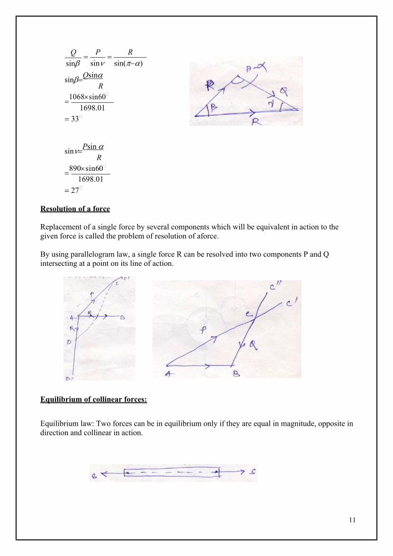
Problem 2: A boat is moved uniformly along a canal by two horses pulling with forces P = 890 N and Q = 1068 N acting under an angle α = 60˚. Determine the magnitude of the resultant pull on the boat and the angles β and ν.
P = 890 N, α = 60˚ Q = 1068 NR (P2Q22PQcos)
(8902 10682289010680.5) 1698.01N
β
αν
11
Qsin
Psin
Rsin()
sinQsinR
1068sin60
1698.01 33
sinPsin R
890sin60
1698.01 27
Resolution of a force
Replacement of a single force by several components which will be equivalent in action to the given force is called the problem of resolution of aforce.
By using parallelogram law, a single force R can be resolved into two components P and Q intersecting at a point on its line of action.
Equilibrium of collinear forces:
Equilibrium law: Two forces can be in equilibrium only if they are equal in magnitude, opposite in direction and collinear in action.
12
Law of superposition
The action of a given system of forces on a rigid body will no way be changed if we add to or subtract from them another system of forces in equllibrium.
Problem 3: Two spheres of weight P and Q rest inside a hollow cylinder which is resting on a horizontal force. Draw the free body diagram of both the spheres, together and separately.
Problem 4: Draw the free body diagram of the figure shown below.
13
915
610
Problem 5: Determine the angles α and β shown in the figure.
tan1 762
3947'
tan1 762
5119'
14
Problem 6: Find the reactions R1 and R2.
Problem 7: Two rollers of weight P and Q are supported by an inclined plane and vertical walls as shown in the figure. Draw the free body diagram of both the rollers separately.
15
Problem 8: Find θn and θt in the following figure.
Problem 9: For the particular position shown in the figure, the connecting rod BA of an engine exert a force of P = 2225 N on the crank pin at A. Resolve this force into two rectangularcomponentsPhandPvhorizontallyandverticallyrespectivelyatA.
Ph = 2081.4 N Pv = 786.5 N
Equilibrium of concurrent forces in a plane
If a body known to be in equilibrium is acted upon by several concurrent, coplanar forces, then these forces or rather their free vectors, when geometrically added must form a closedpolygon.
This system represents the condition of equilibrium for any system of concurrent forces in aplane.
w
16
RawtanS wsec
Lami’s theorem
If three concurrent forces are acting on a body kept in an equllibrium, then each force is proportional to the sine of angle between the other two forces and the constant of proportionality issame.
Psin
Qsin
Rsin
W
S Ra W
sin90 sin180 sin90
S
17
Problem: A ball of weight Q = 53.4N rest in a right angled trough as shown in figure. Determine the forces exerted on the sides of the trough at D and E if all the surfaces are perfectlysmooth.
W
Problem: An electric light fixture of weight Q = 178 N is supported as shown in figure. Determine the tensile forces S1 and S2 in the wires BA and BC, if their angles of inclination aregiven.
S1 S2 178sin135 sin150 sin75
S1 cosP
S = Psecα
18
Rb W S sin
WP
cossin
W P tan
Problem: A right circular roller of weight W rests on a smooth horizontal plane and is held in position by an inclined bar AC. Find the tensions in the bar AC and vertical reaction Rb if there is also a horizontal force P is active.
Theory of transmissiibility of a force:
The point of application of a force may be transmitted along its line of action without changing the effect of force on any rigid body to which it may be applied.
Problem:
19
X 0S1 cos 30 20 sin 60 S2 sin 30
3 S 20 3 S2
2 1
S2
2 23 S 10 3
2 2 1
S2 3S1 20 (1)
Y 0S1 sin 30 S2 cos 30 Sdcos 60 20S1 S2 2
3
20 20
2 2S1
3 S 302 2 2
S1 3S2 60 (2)
Substituting the value of S2 in Eq.2, we get
S1 3 3S1 20 3 60
S1 3S1 60 60 4S1 0S1 0KNS2 20 34.64KN
3
3
20
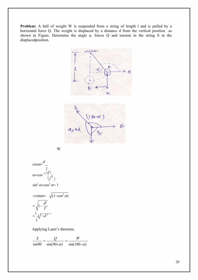
l
Problem: A ball of weight W is suspended from a string of length l and is pulled by a horizontal force Q. The weight is displaced by a distance d from the vertical position as shown in Figure. Determine the angle α, forces Q and tension in the string S in the displacedposition.
W
cosd
lcos1 d
sin2 cos2 1
sin
(1cos2 )
1 l 2 d 2
l
Applying Lami’s theorem,
S Q Wsin90 sin(90) sin(180)
1d2
l2
21
1 l2d2
l2d2
1 l2d2
l2d2
W
Q Wsin(90) sin(180)
W dW cos l
Q
sinl
QWd
S sin
l
Wl
Problem: Two smooth circular cylinders each of weight W = 445 N and radius r = 152 mm are connected at their centres by a string AB of length l = 406 mm and rest upon a horizontal plane, supporting above them a third cylinder of weight Q = 890 N and radius r = 152 mm. Find the forces in the string and the pressures produced on the floor at the point of contact.
cos203
30448.1 Rg Rf
Rg Re
Q
sin138.1 sin138.1 83.8Rg Re 597.86N
Q
W
22
Resolving horizontally
X 0S Rfcos 48.1 597.86 cos 48.1 399.27N
Resolving vertically
Y 0Rd W Rfsin 48.1 445 597.86 sin 48.1 890N
Re 890NS 399.27N
Problem: Two identical rollers each of weight Q = 445 N are supported by an inclined plane and a vertical wall as shown in the figure. Assuming smooth surfaces, find the reactions induced at the points of support A, B and C.
S
Ra S 445sin120 sin150 sin90
Ra 385.38NS 222.5N
23
Resolving vertically
Y 0Rb cos 60 445 S sin 30
Rb3 445222.5 Rc
2 2Rb 642.302N
Resolving horizontally
X 0RcR b sin 30 S cos 30 642.302 sin 30 222.5 cos 30Rc 513.84N
Problem:
A weight Q is suspended from a small ring C supported by two cords AC and BC. The cord AC is fastened at A while cord BC passes over a frictionless pulley at B and carries a weight P. If P = Q and α = 50˚, find the value of β.
Resolving horizontally
X 0S sin 50 Q sin Resolving vertically
Y 0S cos 50 Q sin QS cos 50 Q(1cos)Putting the value of S from Eq. 1, weget
(1)
24
S cos 50 Q sin QS cos 50 Q(1cos)
Qsinsin50
cos 50 Q(1cos)
cot 50 1cos
sin 0.839 sin 1cos
Squaring both sides,0.703sin2 1cos2 2 cos0.703(1cos2 ) 1cos2 2 cos0.703 0.703cos2 1cos2 2 cos 1.703cos2 2 cos 0.297 0cos2 1.174 cos 0.297 0 63.13
25
Method of moments
Moment of a force with respect to a point:
Considering wrench subjected to two forces P and Q of equal magnitude. It is evident that force P will be more effective compared to Q, though they are of equalmagnitude.
The effectiveness of the force as regards it is the tendency to produce rotation of a body about a fixed point is called the moment of the force with respect to that point.
Moment = Magnitude of the force × Perpendicular distance of the line of action offorce. Point O is called moment centre and the perpendicular distance (i.e. OD) is called
momentarm. Unit isN.m
Theorem of Varignon:
The moment of the resultant of two concurrent forces with respect to a centre in their plane is equal to the alzebric sum of the moments of the components with respect to some centre.
Problem 1:
A prismatic clear of AB of length l is hinged at A and supported at B. Neglecting friction, determine the reaction Rb produced at B owing to the weight Q of the bar.
Taking moment about point A,R l Q cos.lb 2
Rb Q cos2
26
Problem 2:
A bar AB of weight Q and length 2l rests on a very small friction less roller at D and against a smooth vertical wall at A. Find the angle α that the bar must make with the horizontal in equilibrium.
B
Resolving vertically,Rd cosQ
Now taking moment about A,Rd .a cos
Q.lcos0
Q.acos2
Q.lcos0
Q.aQ.lcos3 0
cos3 Q.a
Q.l
cos1
Problem 3:
If the piston of the engine has a diameter of 101.6 mm and the gas pressure in the cylinder is 0.69 MPa. Calculate the turning moment M exerted on the crankshaft for the particular configuration.
a3
l
27
380
l
Area of cylinderA (0.1016)2 8.107103 m2
4
Force exerted on connectingrod,
F = Pressure × Area= 0.69×106 × 8.107×10-3
= 5593.83 N
Now sin1 178 27.93
S cosF
S Fcos
6331.29N
Now moment entered on crankshaft,
S cos 0.178 995.7N 1KN
Problem 4:
A rigid bar AB is supported in a vertical plane and carrying a load Qat its free end. Neglecting the weight of bar, find the magnitude of tensile force S in the horizontal string CD.
Taking moment about A,
M A 0
S. cosQ.lsin2
S Q.lsinlcos2
S 2Q.tan
28
MODULE II FRICTION AND BASICS STRUCTURAL ANALYSIS
Friction
The force which opposes the movement or the tendency of movement is called Frictional force or simply friction. It is due to the resistance to motion offered by minutely projecting particles at the contact surfaces. However, there is a limit beyond which the magnitude of this force cannotincrease.
If the applied force is more than this limit, there will be movement of one body over the other. This limiting value of frictional force when the motion is impending, it is known as LimitingFriction.
When the applied force is less than the limiting friction, the body remains at rest and such frictional force is called Static Friction, which will be having any value between zero and the limitingfriction.
If the value of applied force exceeds the limiting friction, the body starts moving over the other body and the frictional resistance experienced by the body while moving is known as Dynamic Friction. Dynamic friction is less than limitingfriction.
Dynamic friction is classified into following twotypes:a) Slidingfrictionb) Rolling friction Sliding friction is the friction experienced by a body when it slides over the other
body. Rolling friction is the friction experienced by a body when it rolls over a surface. It is experimentally found that the magnitude of limiting friction bears a constant ratio
to the normal reaction between two surfaces and this ratio is called Coefficient ofFriction.
W
N
Coefficient of friction = F
Nwhere F is limiting friction and N is normal reaction between the contact surfaces.
Coefficient of friction is denoted by µ.
Thus, F
N
P
F
29
Laws of friction
1. The force of friction always acts in a direction opposite to that in which body tends tomove.
2. Till the limiting value is reached, the magnitude of friction is exactly equal to the force which tends to move thebody.
3. The magnitude of the limiting friction bears a constant ratio to the normal reaction between the two surfaces of contact and this ratio is called coefficient offriction.
4. The force of friction depends upon the roughness/smoothness of thesurfaces.5. The force of friction is independent of the area of contact between the two surfaces.6. After the body starts moving, the dynamic friction comes into play, the magnitude of
which is less than that of limiting friction and it bears a constant ratio with normal force. This ratio is called coefficient of dynamicfriction.
Angle of friction
Consider the block shown in figure resting on a horizontal surface and subjected to horizontal pull P. Let F be the frictional force developed and N the normal reaction. Thus, at contact surface the reactions are F and N. They can be graphically combined to get the reaction R which acts at angle θ to normal reaction. This angle θ called the angle of friction is givenby
tanF
N
As P increases, F increases and hence θ also increases. θ can reach the maximum value α when F reaches limiting value. At this stage,
tanF
N
This value of α is called Angle of Limiting Friction. Hence, the angle of limiting friction may be defined as the angle between the resultant reaction and the normal to the plane on which the motion of the body is impending.
Angle of repose
30
Consider the block of weight W resting on an inclined plane which makes an angle θ with the horizontal. When θ is small, the block will rest on the plane. If θ is gradually increased, a stage is reached at which the block start sliding down the plane. The angle θ for which the motion is impending, is called the angle of repose. Thus, the maximum inclination of the plane on which a body, free from external forces, can repose is called Angle of Repose.
Resolving vertically, N = W. cos θ
Resolving horizontally, F = W. sin θ
Thus, tan F
NIf ɸ is the value of θ when the motion is impending, the frictional force will be limiting friction and hence,
tanF
NtanThus, the value of angle of repose is same as the value of limiting angle of repose.
Cone of friction
When a body is having impending motion in the direction of force P, the frictional force will be limiting friction and the resultant reaction R will make limiting angle α with thenormal.
If the body is having impending motion in some other direction, the resultant reaction makes limiting frictional angle α with the normal to that direction. Thus, when the direction of force P is gradually changed through 360˚, the resultant R generates a right circular cone with semi-central angle equal toα.
31
Problem 1: Block A weighing 1000N rests over block B which weighs 2000N as shown in figure. Block A is tied to wall with a horizontal string. If the coefficient of friction between blocks A and B is 0.25 and between B and floor is 1/3, what should be the value of P to move the block (B), if
(a) P ishorizontal.(b) P acts at 30˚ upwards tohorizontal.
Problem 2: A block weighing 500N just starts moving down a rough inclined plane when supported by a force of 200N acting parallel to the plane in upward direction. The same block is on the verge of moving up the plane when pulled by a force of 300N acting parallel to the plane. Find the inclination of the plane and coefficient of friction between the inclined plane and theblock.
V 0N 500.cosF1 N .500 cos
33
H 0200 F1 500.sin 200 .500 cos 500.sin
V 0N 500.cosF2 N .500.cos
H 0500 sinF2 300 500 sin.500 cos 300Adding Eqs. (1) and (2), we get
500 = 1000. sinθ sin θ = 0.5θ = 30˚
Substituting the value of θ in Eq. 2, 500 sin 30 .500 cos 30 300
(1)
(2)
50500cos30
0.11547
34
P R
Q
l
Parallel forces on a plane
Like parallel forces: Coplanar parallel forces when act in the same direction. Unlike
parallel forces: Coplanar parallel forces when act in different direction. Resultant of
like parallel forces:
Let P and Q are two like parallel forces act at points A and B. R = P + Q
A B
Resultant of unlikeparallelforces: P R = P-Q R
BR is in the direction of the force havinggreatermagnitude. A
Q
Couple:
Two unlike equal parallel forces form a couple.
P
A B
P
The rotational effect of a couple is measured by its moment.
Problem 1 :A rigid bar CABD supported as shown in figure is acted upon by two equal horizontal forces P applied at C and D. Calculate the reactions that will be induced at the points of support. Assume l = 1.2 m, a = 0.9 m, b =0.6 m.
V 0
Ra Rb
Taking moment about A,Ra Rb
Rb l P b P a
Rb P(0.9 0.6) 1.2
Rb 0.25P()Ra 0.25P()
Problem 2: Owing to weight W of the locomotive shown in figure, the reactions at the two points of support A and B will each be equal to W/2. When the locomotive is pulling the train and the drawbar pull P is just equal to the total friction at the points of contact A and B, determine the magnitudes of the vertical reactions Ra and Rb.
V 0Ra Rb W
Taking moment about B,
36
MB 0Ra 2a P b W a
Ra W .a P.b2a
Rb W Ra
R WW.aP.bb 2a
Rb
W .a P.b2a
Problem 3: The four wheels of a locomotive produce vertical forces on the horizontal girder AB. Determine the reactions Ra and Rb at the supports if the loads P = 90 KN each and Q = 72 KN (All dimensions are in m).
V 0Ra Rb 3P QRa Rb 3 90 72Ra Rb 342KN
M A 0Rb 9.6 90 1.8 90 3.6 90 5.4 72 8.4Rb 164.25KNRa 177.75KN
Problem 4: The beam AB in figure is hinged at A and supported at B by a vertical cord which passes over a frictionless pulley at C and carries at its end a load P. Determine the distance x from A at which a load Q must be placed on the beam if it is to remain in equilibrium in a horizontal position. Neglect the weight of thebeam.
FBD
37
OR
M A 0S l Q x
xP.lQ
Problem 5: A prismatic bar AB of weight Q = 44.5 N is supported by two vertical wires at its ends and carries at D a load P = 89 N as shown in figure. Determine the forces Sa and Sb in the two wires.
Q = 44.5 N P = 89 N
Resolving vertically,
V 0SaSb P QSaSb 89 44.5SaSb 133.5N
38
M A 0
S l P l Q l
b 4 2
Sb
Sb
PQ4 2
89 44.54 2
Sb 44.5Sa 133.5 44.5Sa 89N
39
c
c
MODULE IIICENTROID AND CENTRE OF GRAVITY AND VIRTUAL WORK AND
ENERGY METHOD
Centre of gravity
Centre of gravity: It is that point through which the resultant of the distributed gravity force passes regardless of the orientation of the body in space.
As the point through which resultant of force of gravity (weight) of the bodyacts.
Centroid: Centrroid of an area lies on the axis of symmetry if it exits.
Centre of gravity is applied to bodies with mass and weight and centroid is applied to plane areas.
xcAixiyc
Aiyi
x A1x1 A2 x2
A1 A2
y A1 y1 A2y2
A1 A2
xy Moment of areac c Totalarea
x x.dAc A
y y.dAc A
40
h2 3
Problem 1: Consider the triangle ABC of base ‘b’ and height ‘h’. Determine the distance of centroid from the base.
Let us consider an elemental strip of width ‘b1’ and thickness ‘dy’.
AEF ABC
b1 h y bh
bbh y1 h
bb1
y
1 h
Area of element EF (dA) = b1×dyb1
y dy h
yy.dAc Ah
y
y.b1h
dy
0 1 b.h2
y2b y3
h
2 3h 01b.h2
2 h2
h3
2
h2
h 6
h3Therefore, yc is at a distance of h/3 from base.
41
3
Problem 2: Consider a semi-circle of radius R. Determine its distance from diametral axis.
Due to symmetry, centroid ‘yc’ must lie on Y-axis.
Consider an element at a distance ‘r’ from centre ‘o’ of the semicircle with radial width dr.
Area of element = (r.dθ)×dr
Moment of area about x = y.dA R
r.d.drr.sin00 R
r 2 sin.dr.d0 0
r 2.dr.sin.d0 0 r3
R
0 0R3
.sin.d
.sin.d0 3
R3
cos
3
R3
3
0
11
2 R3
3
yMoment of areac Totalarea
R
42
23 R
3
R2
2
4R 3
Centroids of different figures
Shape Figure x y AreaRectangle b
2d2
bd
Triangle 0 h3
bh2
Semicircle 0 4R3
r2
2
Quarter circle 4R3
4R3
r2
4
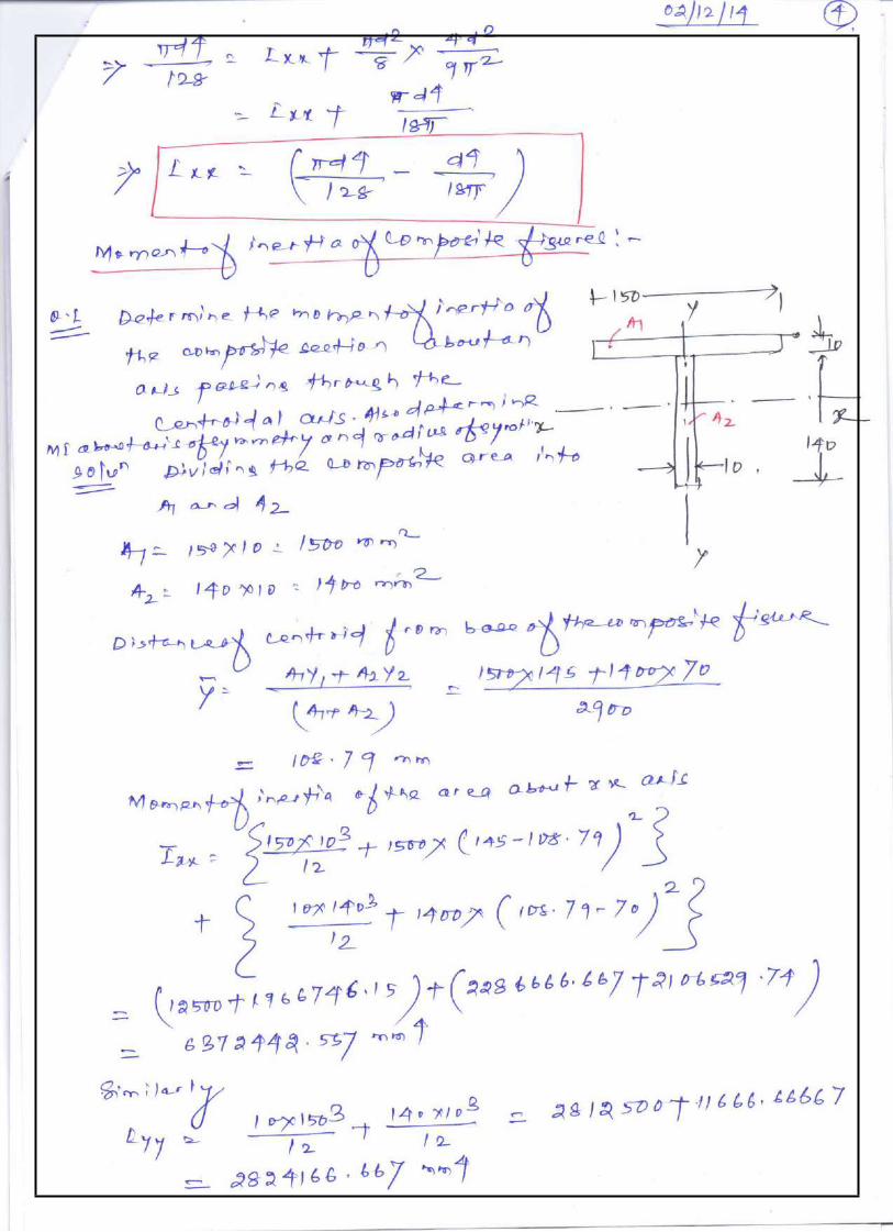
Problem 3: Find the centroid of the T-section as shown in figure from the bottom.
1
2
43
Area (Ai) xi yi Ai xi Aiyi2000 0 110 10,000 22,00002000 0 50 10,000 10,00004000 20,000 32,0000
yAiyiA1 y1 A2 y2 32, 0000 80c A AA 4000i 1 2
Due to symmetry, the centroid lies on Y-axis and it is at distance of 80 mm from the bottom.
Problem 4: Locate the centroid of the I-section.
As the figure is symmetric, centroid lies on y-axis. Therefore, x = 0
Area (Ai) xi yi Ai xi Aiyi2000 0 140 0 2800002000 0 80 0 1600004500 0 15 0 67500
yAiyi A1 y1 A2 y2 A3 y3 59.71mm
c A AAAi 1 2 3
Thus, the centroid is on the symmetric axis at a distance 59.71 mm from the bottom.
Problem 5: Determine the centroid of the composite figure about x-y coordinate. Take x = 40 mm.
A1 = Area of rectangle = 12x.14x=168x2
A2 = Area of rectangle to be subtracted = 4x.4x = 16 x2
44
2
2
A3 = Area of semicircle to be subtracted = R2 4x 2
25.13x2
2 2
A4 = Area of quatercircle to be subtracted = R2 4x 2
12.56x2
A5 = Area of triangle =441 6x 4x 12x2
2
Area (Ai) xi yi Ai xi AiyiA1 = 268800 7x = 280 6x =240 75264000 64512000A2 = 25600 2x = 80 10x=400 2048000 10240000A3 = 40208 6x =240 4 4x =67.906
Problem 6: Determine the centroid of the following figure.
A1 = Area of triangle =1
80 80 3200m2
2
A2 = Area of semicircle= d2 R2
2513.274m
A3 = Area of semicircle
8 2D2
1256.64m2
45
i 1 2 3
Area (Ai) xi yi Ai xi Aiyi3200 2×(80/3)=53.33 80/3 = 26.67 170656 853442513.274 40 4 40
16.973
100530.96 -42650.259
1256.64 40 0 50265.6 0
xA1x1 A2 x2 A3x3 49.57mm
c A AA1 2 3
yA1 y1 A2 y2 A3 y3 9.58mm
c A AA1 2 3
Problem 7: Determine the centroid of the following figure.
A1 = Area of the rectangle A2 = Area of triangleA3 = Area of circle
Area (Ai) xi yi Ai xi Aiyi30,000 100 75 3000000 22500003750 100+200/3
= 166.6775+150/3=125
625012.5 468750
7853.98 100 75 785398 589048.5
x Aixi A1x1 A2 x2 A3x3 86.4mm
cA AAAi
y Aiyi
1 2 3
A1 y1 A2 y2 A3 y3 64.8mm
cA AAA
46
Numerical Problems (Assignment)
1. An isosceles triangle ADE is to cut from a square ABCD of dimension ‘a’. Find the altitude ‘y’ of the triangle so that vertex E will be centroid of remaining shadedarea.
2. Find the centroid of the followingfigure.
3. Locate the centroid C of the shaded area obtained by cutting a semi-circle of diameter ‘a’ from the quadrant of a circle of radius‘a’.
4. Locate the centroid of the compositefigure.
47
Truss/ Frame: A pin jointed frame is a structure made of slender (cross-sectional dimensions quite small compared to length) members pin connected at ends and capable of taking load at joints.
Such frames are used as roof trusses to support sloping roofs and as bridge trusses to support deck.
Plane frame: A frame in which all members lie in a single plane is called plane frame. They are designed to resist the forces acting in the plane of frame. Roof trusses and bridge trusses are the example of plane frames.
Space frame: If all the members of frame do not lie in a single plane, they are called as space frame. Tripod, transmission towers are the examples of spaceframes.
Perfect frame: A pin jointed frame which has got just sufficient number of members to resist the loads without undergoing appreciable deformation in shape is called a perfect frame. Triangular frame is the simplest perfect frame and it has 03 joints and 03members.
It may be observed that to increase one joint in a perfect frame, two more members are required. Hence, the following expression may be written as the relationship between number of joint j, and the number of members m in a perfect frame.
m = 2j – 3
(a) When LHS = RHS, Perfectframe.(b) When LHS<RHS, Deficientframe.(c) When LHS>RHS, Redundantframe.
Assumptions
The following assumptions are made in the analysis of pin jointed trusses:
1.The ends of the members are pin jointed(hinged).2.The loads act only at thejoints.3.Self weight of the members isnegligible.
Methods of analysis
1.Method ofjoint2.Method ofsection
48
Problems on method of joints
Problem 1: Find the forces in all the members of the truss shown in figure.
tan 1 45
Joint C
S1S2cos45S140KN(Compression)S2 sin 45 40S2 56.56KN (Tension)
Joint D
S3 40KN (Tension)S1 S4 40KN (Compression) Joint
B
Resolving vertically,
V 0S5 sin 45 S3 S2 sin 45
49
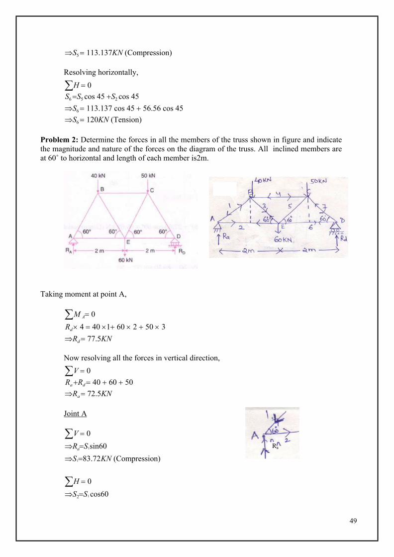
S5 113.137KN (Compression)
Resolving horizontally,
H 0S6 S5 cos 45 S2 cos 45S6 113.137 cos 45 56.56 cos 45S6 120KN (Tension)
Problem 2: Determine the forces in all the members of the truss shown in figure and indicate the magnitude and nature of the forces on the diagram of the truss. All inclined members are at 60˚ to horizontal and length of each member is2m.
Taking moment at point A,
M A 0Rd 4 40 1 60 2 50 3Rd 77.5KN
Now resolving all the forces in vertical direction,
V 0Ra Rd 40 60 50Ra 72.5KN
Joint A
V 0RaS1sin60S183.72KN (Compression)
H 0S2S1 cos60
Ra
50
S141.86KN(Tension)
Joint D
V 0S7 sin 60 77.5S7 89.5KN (Compression)
H 0S6 S7 cos 60S6 44.75KN (Tension)
Joint B
V 0S1 sin 60 S3 cos 60 40S3 37.532KN (Tension)
H 0S4 S1 cos 60 S3 cos 60S4 37.532 cos 60 83.72 cos 60S4 60.626KN (Compression)
Joint C
V 0S5 sin 60 50 S7 sin 60S5 31.76KN (Tension)
51
52
53
54
55
56
57
58
59
60
61
62
63
64
65
66
67
68
MODULE IVPARTICLE DYNAMICS AND INTRODUCTION TO KINETICS
69
70
71
72
73
74
75
76
77
78
79
80
81
82
83
84
85
86
87
88
89
90
91
92
93
94
95
96
97
98
99
100
101
102
MODULE VMECHANICAL VIBRATIONS
Definitions and Concepts
Amplitude :Maximum displacement from equilibrium position; the distance from the midpoint of a wave to its crest or trough.
Equilibrium position: The position about which an object in harmonic motion oscillates; the center of vibration.
Frequency: The number of vibrations per unit of time.
Hooke’s law: Law that states that the restoring force applied by a spring is proportional to the displacement of the spring and opposite in direction.
Ideal spring: Any spring that obeys Hooke’s law and does not dissipate energy within the spring.
Mechanical resonance: Condition in which natural oscillation frequency equals frequency of a driving force.
Period: The time for one complete cycle of oscillation.
Periodic motion: Motion that repeats itself at regular intervals of time.
Restoring force:The force acting on an oscillating object which is proportional to the displacement and always points toward the equilibrium position.
Simple harmonic motion: Regular, repeated, friction-free motion in which the restoring force has the mathematical form F = - kx.
Simple Harmonic Motion
A pendulum, a mass on a spring, and many other kinds of oscillators exhibit a special kind of oscillatory motion called Simple Harmonic Motion (SHM).
SHM occurs whenever :
i. h
ere is a restoring force proportional to the displacement from equilibrium: F x
ii. t
he potential energy is proportional to the square of the displacement: PE x2
iii. t
he period T or frequency f = 1 / T is independent of the amplitude of the motion.
iv. t
he position x, the velocity v, and the acceleration a are all sinusoidal in time.
103
x
t
v
t
(Sinusoidal means sine, cosine, or anything in between.)As we will see, any one of these four properties guarantees the other three. If one of these 4 things is true, then the oscillator is a simple harmonic oscillator and all 4 things must be true.
Not every kind of oscillation is SHM. For instance, a perfectly elastic ball bouncing up and down on a floor: the ball's position (height) is oscillating up and down, but none of the 4 conditions above is satisfied, so this is not an example of SHM.
A mass on a spring is the simplest kind of Simple Harmonic Oscillator.
Hooke's Law: Fspring = – k x
(–) sign because direction of Fspring is opposite to the direction of displacement vector x(bold font indicates vector)
k = spring constant = stiffness,units [k] = N / m
Big k = stiff spring
Definition: amplitudeA = |xmax| = |xmin|.
Mass oscillates between extreme positions x = +A and x = –A
Notice that Hooke's Law (F = kx) is condition i : restoring force proportional to the displacement from equilibrium. We showed previously (Work and Energy Chapter) that for a spring obeying Hooke's Law, the potential energy is U = (1/2)kx2 , which is condition ii. Also, in the chapter on Conservation of Energy, we showed that F = dU/dx, from which it follows that condition ii implies condition i. Thus, Hooke's Law and quadratic PE (U x2) are equivalent.
We now show that Hooke's Law guarantees conditions iii (period independent of amplitude) and iv (sinusoidal motion).
We begin by deriving the differential equation for SHM. A differential equation is simply an equation containing a derivative. Since the motion is 1D, we can drop the vector arrows and use sign to indicate direction.
net net2
2 22
F m a and F k x m a k xd x ka dv / dt d x / dt xd t m
The constants k and m and both positive, so the k/m is always positive, always. For notational convenience, we write . (The square on the reminds us that 2 is always positive.) The differential equation 2k / m becomes
x
relaxed: x = 0
mx
Frestore
Frestore
x
k
x
m
+A–A 0
104
(equation of SHM)
22
2
d x xd t
This is the differential equation for SHM. We seek a solution x = x(t) to this equation, a function x = x(t) whose second time derivative is the function x(t) multiplied by a negative constant (2 = k/m). The way you solve differential equations is the same way you solve integrals: you guess the solution and then check that the solution works.
Based on observation, sinusoidal solution: , x(t) A cos t
where A, are any constants and (as we'll show) .km
A = amplitude: x oscillates between +A and –A
= phase constant (more on this later)
Danger: t and have units of radians (not degrees). So set your calculators to radians when using this formula.
Just as with circular motion, the angular frequency for SHM is related to the period by
, T = period. 22 fT
(What does SHM have to do with circular motion? We'll see later.)
Let's check that is a solution of the SHM equation. x(t) A cos t
Taking the first derivative dx/dt , we get . dxv(t) A sin tdt
Here, we've used the Chain Rule: d d cos( ) dcos t , ( t )
dt d d tsin sin( t )
Taking a second derivative, we get
22
2
22
2
22
2
d x dv da(t) A sin t A cos( t )dt dt dt
d x A cos( t )dtd x xdt
This is the SHM equation, with 2 k k,m m
We have shown that our assumed solution is indeed a solution of the SHM equation. (I leave to the mathematicians to show that this solution is unique. Physicists seldom worry about that kind of thing, since we know that nature usually provides only one solution for physical systems, such as masses on springs.)
We have also shown condition iv: x, v, and a are all sinusoidal functions of time:
105
2
x(t) A cos tv(t) A sin( t )a(t) A cos( t )
The period T is given by . We see that T does not depend on the k 2 mT 2m T k
amplitude A (condition iii).
Let's first try to make sense of : big means small T which means rapid oscillations. According to k / m the formula, we get a big when k is big and m is small. This makes sense: a big k (stiff spring) and a small mass m will indeed produce very rapid oscillations and a big .
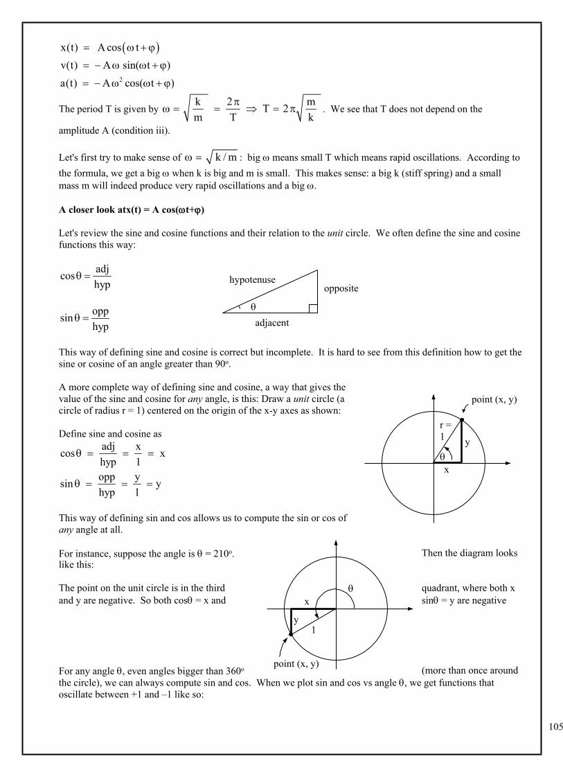
A closer look atx(t) = A cos(t+)
Let's review the sine and cosine functions and their relation to the unit circle. We often define the sine and cosine functions this way:
adjcoshyp
oppsinhyp
This way of defining sine and cosine is correct but incomplete. It is hard to see from this definition how to get the sine or cosine of an angle greater than 90o.
A more complete way of defining sine and cosine, a way that gives the value of the sine and cosine for any angle, is this: Draw a unit circle (a circle of radius r = 1) centered on the origin of the x-y axes as shown:
Define sine and cosine asadj xcos xhyp 1
opp ysin yhyp 1
This way of defining sin and cos allows us to compute the sin or cos of any angle at all.
For instance, suppose the angle is = 210o. Then the diagram looks like this:
The point on the unit circle is in the third quadrant, where both x and y are negative. So both cos = x and sin = y are negative
For any angle , even angles bigger than 360o (more than once around the circle), we can always compute sin and cos. When we plot sin and cos vs angle , we get functions that oscillate between +1 and –1 like so:
opposite
adjacent
hypotenuse
x
y
r =1
point (x, y)
x
y
1
point (x, y)
106
cos
sin
= 3600 = 2 rad+1
–1 = 2
–1
+1
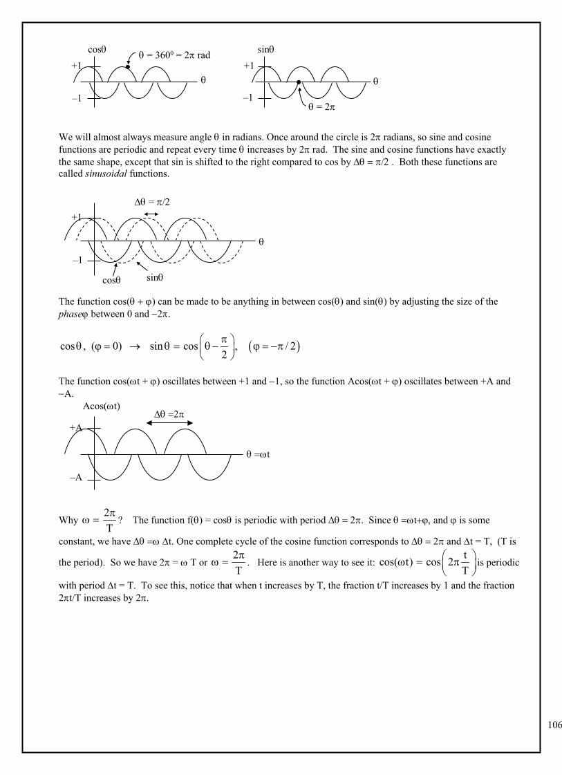
We will almost always measure angle in radians. Once around the circle is 2 radians, so sine and cosine functions are periodic and repeat every time increases by 2 rad. The sine and cosine functions have exactly the same shape, except that sin is shifted to the right compared to cos by . Both these functions are called sinusoidal functions.
cos
sin
= +1
–1
The function cos( ) can be made to be anything in between cos() and sin() by adjusting the size of the phase between 0 and 2.
cos , ( 0) sin cos , / 22
The function cos(t + ) oscillates between +1 and 1, so the function Acos(t + ) oscillates between +A and A.
t
Acos(t)
+A
–A
Why ? The function f() = cos is periodic with period . Since t and is some 2T
constant, we have t. One complete cycle of the cosine function corresponds to and t = T, (T is
the period). So we have 2 = T or . Here is another way to see it: is periodic 2T
tcos( t) cos 2T
with period t = T. To see this, notice that when t increases by T, the fraction t/T increases by 1 and the fraction 2t/T increases by 2.
107
t
Acos(t)
+A
–A
t = T
t
Acos(t)
+A
–A
t) = 2
Now back to simple harmonic motion. Instead of a circle of radius 1, we have a circle of radius A (where A is the amplitude of the Simple Harmonic Motion).
SHM and Conservation of Energy:
Recall PEelastic = (1/2) k x2 = work done to compress or stretch a spring by distance x.
If there is no friction, then the total energy Etot = KE + PE = constant during oscillation. The value of Etot depends on initial conditions – where the mass is and how fast it is moving initially. But once the mass is set in motion, Etot stays constant (assuming no dissipation.)
At any position x, speed v is such that . 2 21 1tot2 2m v k x E
When |x| = A, then v = 0, and all the energy is PE: 2
tot0 (1/ 2)kA
KE PE E
So total energy 21tot 2E k A
When x = 0, v = vmax, and all the energy is KE: 2
max
tot0(1/ 2)mv
KE PE E
So, total energy . 21tot max2E m v
x
y
Etot =KE + PE
(1/2)kx2
PE
+AA
KE
So, we can relate vmax to amplitude A :PEmax = KEmax = Etot 2 21 1max2 2k A m v
maxkv Am
108
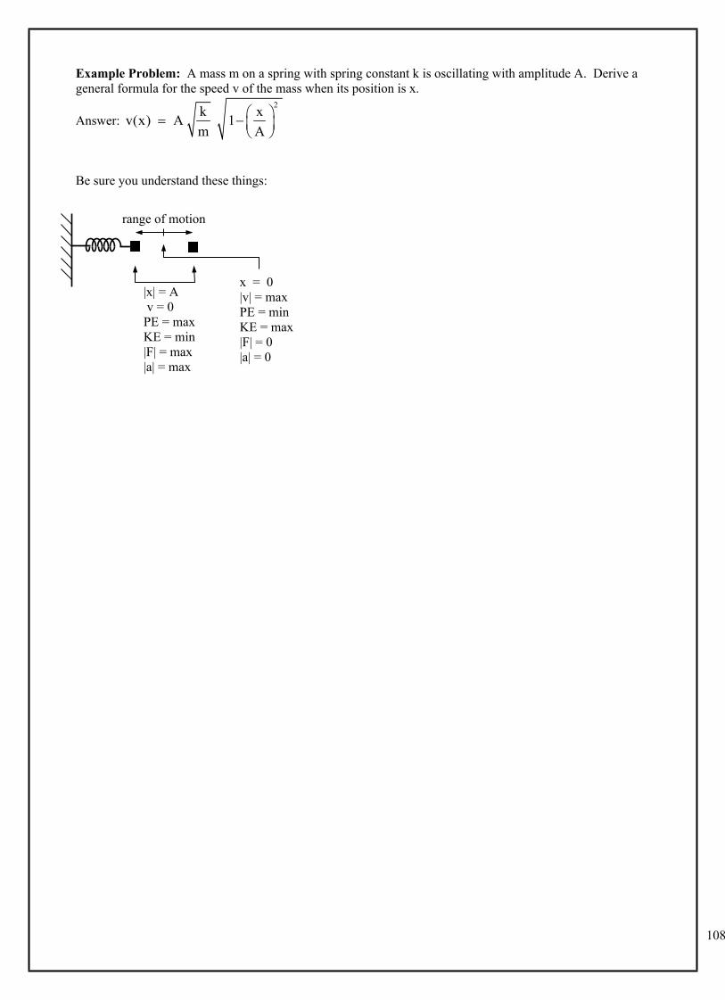
Example Problem: A mass m on a spring with spring constant k is oscillating with amplitude A. Derive a general formula for the speed v of the mass when its position is x.
Answer: 2k xv(x) A 1
m A
Be sure you understand these things:
range of motion
|x| = A v = 0PE = maxKE = min|F| = max|a| = max
x = 0|v| = maxPE = minKE = max|F| = 0|a| = 0
109
Pendulum Motion
A simple pendulum consists of a small mass m suspended at the end of a massless string of length L. A pendulum executes SHM, ifthe amplitude is not too large.
L
x
x / L (rads)
Forces on mass :
FT = tension
mg
mg cosmg sin
yx
The restoring force is the component of the force along the direction of motion: xrestoring force = mgsin mg mgL
Claim: when is small. sin (rads) hsinL
sR
If small, then h s, and L R,so sin .
Try it on your calculator: = 5o = 0.087266..rad, sin = 0.087156..
is exactly like Hooke's Law , except we have replaced the constant k with restoremgF xL
restoreF k x
another constant (mg / L). The math is exactly the same as with a mass on a spring; all results are the same, except we replace k with (mg/L).
spring pendm m LT 2 T 2 2k mg / L g
Notice that the period is independent of the amplitude; the period depends only on length L and acceleration of gravity. (But this is true only if is not too large.)
R
Ls h
110
SHM and circular motion
There is an exact analogy between SHM and circular motion. Consider a particle moving with constant speed v around the rim of a circle of radius A. The x-component of the position of the particle has exactly the same mathematical form as the motion of a mass on a spring executing SHM with amplitude A.
Angular velocity d constd t
sot
x A cos A cos t This same formula also describes the sinusoidal motion of a mass on a spring.
That the same formula applies for two different situations (mass on a spring & circular motion) is no accident. The two situations have the same solution because they both obey the same equation. As Feynman said, "The
same equations have the same solutions". The equation of SHM is . We now show that a 2
22
d x xd t
particle in circular motion obeys this same SHM equation.
Recall that for circular motion with angular speed , the acceleration of a the particle is toward the center and has
magnitude . Since v = R , we can rewrite this as 2v| a |
R 2
2R| a | R
R
Let's set the origin at the center of the circle so the position vector R is along the radius. Notice that the acceleration vector a is always in the direction opposite the position vector R . Since
, the 2| a | R vectors a and R are
related by . The x-2a R
component of this vector equation is: . If we 2
x xa R write Rx = x , then we
have , 2
22
d x xd t
which is the SHM
equation. Done.
Example A mass of 0.5 kg oscillates on the end of a spring on a horizontal surface with negligible friction according to the equation . The graph of F vs. x for this motion is shown below. tAx cos
A
+A–A
0
v
x
a
+A–A
0
v
t
x
R
111
The last data point corresponds to the maximum displacement of the mass. Determine the (a) angular frequency ω of the oscillation,(b) frequencyf of oscillation,(c) amplitude of oscillation,(d) displacement from equilibrium position (x = 0) at a time of 2 s.
Solution:(a) We know that the spring constant k = 50 N/m from when we looked at this graph earlier. So,
srad
kgmN
mk 10
5.0/50
(b) Hzsradf 6.12
/102
(c) The amplitude corresponds to the last displacement on the graph, A = 1.2 m.(d) mssradmtAx 5.02/10cos2.1cos
Example A spring of constant k = 100 N/m hangs at its natural length from a fixed stand. A mass of 3 kg is hung on the end of the spring, and slowly let down until the spring and mass hang at their new equilibrium position.
x
112
(a) Find the value of the quantity x in the figure above.The spring is now pulled down an additional distance x and released from rest. (b) What is the potential energy in the spring at this distance?(c) What is the speed of the mass as it passes the equilibrium position?(d) How high above the point of release will the mass rise?(e) What is the period of oscillation for the mass?
Solution:(a) As it hangs in equilibrium, the upward spring force must be equal and opposite to the downward weight of the block.
mmN
smkgk
mgx
mgkxmgFs
3.0/100
/103 2
(b) The potential energy in the spring is related to the displacement from equilibrium position by the equation
JmmNkxU 5.43.0/10021
21 22
(c) Since energy is conserved during the oscillation of the mass, the kinetic energy of the mass as it passes through the equilibrium position is equal to the potential energy at the amplitude. Thus,
smkg
JmUv
mvUK
/7.13
5.42221 2
(d) Since the amplitude of the oscillation is 0.3 m, it will rise to 0.3 m above the equilibrium position.
(e) smN
kgkmT 1.1
/100322
Example A pendulum of mass 0.4 kg and length 0.6 m is pulled back and released from and angle of 10˚ to the vertical.
(a) What is the potential energy of the mass at the instant it is released. Choose potential energy to be zero at the bottom of the swing. (b) What is the speed of the mass as it passes its lowest point?
This same pendulum is taken to another planet where its period is 1.0 second. (c) What is the acceleration due to gravity on this planet?
Solution(a) First we must find the height above the lowest point in the swing at the instant the pendulum is released.
Recall from chapter 1 of this study guidethat .cosLLh Then
JmmsmkgU
LLmgU4.010cos6.06.0/104.0
cos2
(b) Conservation of energy:
mg
Fs
h
10˚L
L
113
smkg
JmUv
mvKU
/4.14.04.022
21 2
maxmax
(c)
22
2
2
2
7.230.1
6.044
2
sm
sm
TLg
gLT
COMPOUND PENDULUM
AIM:The aim of this experiment is to measure g using a compound pendulum.
YOU WILL NEED:
WHAT TO DO:
First put the knife edge through the hole in the metre rule nearest end A, and record the time for 10 oscillations. Hence work out the time for one oscillation (T).Repeat this for each hole in the ruler for a series of different distances (d) from end A.
ANALYSIS AND CALCULATIONS:Plot a graph of T against d.From the graph record a series of values of the simple equivalent pendulum (L).Calculate the value of g from the graph or from the formula:
T2 = 42L/g
Torsion Pendulum:
1. IntroductionTorsion is a type of stress, which is easier to explain for a uniform wire or a rod when one end of the wire is fixed, and the other end is twisted about the axis of the wire by an external force. The external force causes deformation of the wire and appearance of counterforce in the material. If this end is released, the internal torsion force acts to restore the initial shape and size of the wire. This behavior is similar to the one of the released end of a linear spring with a mass attached.
Attaching a mass to the twisting end of the wire, one can produce a torsion pendulum with circular oscillation of the mass in the plane perpendicular to the axis of the wire.
To derive equations of rotational motion of the torsion pendulum, it would be useful to recall a resemblance of quantities in linear and rotational motion. We know that if initially a mass is motionless, its linear motion is caused by force F; correspondingly, if an extended body does not rotate initially, its rotation is caused by torque τ. The measure of inertia in linear motion is mass, m, while the measure of inertia in rotational motion is the moment of inertia about an axis of rotation, I. For linear and angular displacement in a one-dimensional problem, we use either x or θ. Thus, the two equations of motion are:
T
G-h
h2h1
+h
L
h h
mg
O
G
114
Fx = maxand τ = Iα (1)
whereax and α are the linear and the angular acceleration.If the linear motion is caused by elastic, or spring, force, the Hooke’s law gives Fx = -kx, where k is the spring constant. If the rotation is caused by torsion, the Hooke’s law must result in
τ = -қθ (2)
whereқ is the torsion constant, or torsional stiffness, that depends on properties of the wire. It is essentially a measure of the amount of torque required to rotate the free end of the wire 1 radian.
Your answer to the Preparatory Question 2 gives the following relationship between the moment of inertiaI of an oscillating object and the period of oscillation Tas:
This relationship is true for oscillation where damping is negligible and can be ignored. Otherwise the relationship between I and κ is given by
(3*)20
I
whereω0can be found from (3**) 2
20 2
Ic
= 2πf; f is the frequency of damped oscillation; and c is the damping coefficient. T 2
The relationship between the torsion constant κand the diameter of the wired is given in [3] (check your answer to the Preparatory Question 1) as
(4)l
Gd32
4
wherel is the length of the wire andG is the shear modulus for the material of the wire.
As any mechanical motion, the torsional oscillation is damped by resistive force originating from excitation of thermal modes of oscillation of atoms inside the crystal lattice of the wire and air resistance to the motion of the oscillating object. We can estimate the torque of the resistive force as being directly proportional to the angular speed of the twisting wire, i.e. the torque τR= -cdθ/dt (recall the drag force on mass on spring in viscose medium as R = -bv). Combining Eq.(1), (2) and the expression for τR, we obtain the equation of motion of a torsional pendulum as follows:
(5)02
2
dtdc
dtdI
The solution of Eq.(5) is similar to the solution of the equation for damped oscillation of a mass on spring and is given by:
(6) tAe t cos
where = c/2I (7)
and = -1 with β being the time constant of the damped oscillation; c is the damping coefficient; ω is the angular frequency of torsional oscillation measured in the experiment; and φ can be made zero by releasing the object on the wire at a position of the greatest deviation from equilibrium.
115
Equation (6) can be used to calculate c (damping coefficient) and (time constant = amount of time to decaye times) with DataStudio interface and software.
Another important formula is = ω0/2Q, where Q is the quality factor and ω02= κ / I (see Eq.3’). The ratio
ζ = α/ω0 = (2Q)-1 (8) is called the damping ratio.
Free vibration of One Degree of Freedom Systems
Free vibration of a system is vibration due to its own internal forces (free of external impressive forces). It is initiated by an initial deviation (an energy input) of the system from its static equilibrium position. Once the initial deviation (a displacement or a velocity or both) is suddenly withdrawn, the strain energy stored in the system forces the system to return to its original, static equilibrium configuration. Due to the inertia of the system, the system will not return to the equilibrium configuration in a straightforward way. Instead it will oscillate about this position free vibration.
A system experiencing free vibration oscillates at one or more of its natural frequencies, which are properties of its mass and stiffness distribution. If there is no damping (an undamped system), the system vibrates at the (undamped) frequency (frequencies) forever. Otherwise, it vibrates at the (damped) frequency (frequencies) and dies out gradually. When damping is not large, as in most cases in engineering, undamped and damped frequencies are very close. Therefore usually no distinction is made between the two types of frequencies.
The number of natural frequencies of a system equals to the number of its degrees-of-freedom. Normally, the low frequencies are more important.
Damping always exists in materials. This damping is called material damping, which is always positive (dissipating energy). However, air flow, friction and others may ‘present’ negative damping.Undamped Free Vibration
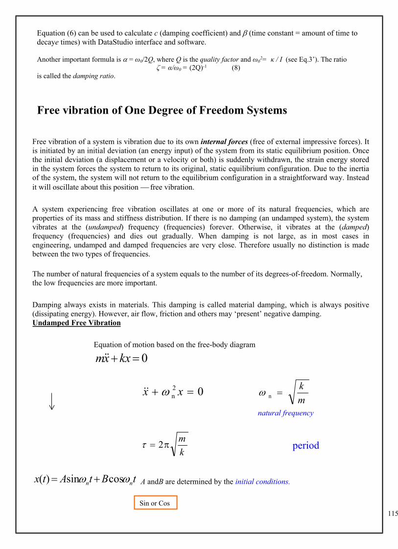
Equation of motion based on the free-body diagram
0 kxxm
02n xx
mk
n
natural frequency
km
2
A andB are determined by the initial conditions.tBtAtx nn cossin)(
Sin or Cos ?
period
116
txtxtx nnn
cos)0(sin)0()(
where)sin()]0([)0(n
22
n
txx
)0()0(arctan
xx n
Vibration of a pendulumHow to establish the equation of motion?
What is its natural frequency?
sin2 mglml 0sin gl
0 gl lg
n
Systems with Rotational Degrees-of-Freedom
Equation of Motion
0o KJ
natural frequencyo
n JK
Systems involving rotational degrees-of-freedom are always more difficult to deal with, in particular when translational degrees-of-freedom are also present. Gear care is needed to identify both degrees-of-freedom and construct suitable equations of motion.
?)0(?)0(?? n
xx
K
Jo
117
Damped Free Vibration (first hurdle in studying vibration)
xckxxm 0 kxxcxm
standard equation 02 2nn xxx
damping factor kmc
mc
22 n
1. oscillatory motion (under-damped )1
)]1exp()1exp()[exp()( n2
2n2
1n tCtCttx
)cossin)(exp()( ddn tBtAttx )sin()exp( dn ttX
]cos)0(sin)0()0()[exp()( ddd
nn txtxxttx
2nd 1
2. nonoscillatory motion (over-damped )1
)]1exp()1exp()[exp()( n2
n2
n tBtAttx
m
k
c
damped natural frequency
x
118
3. critically damped motion ( )1
)exp()()( ntBtAtx
4. negative damping of as a special case of : 0 1
)]1exp()1exp()[exp()( n2
2n2
1n tCtCttx
Divergent oscillatory motion (flutter) due to negative damping
Determination of Damping
positive
119
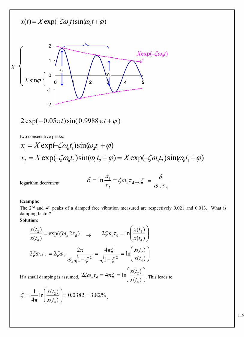
)sin()exp()( dn ttXtx
-2
-1
0
1
2
0 1 2 3 4 5
)9988.0sin()05.0exp(2 tt
two consecutive peaks:
)sin()exp()sin()exp()sin()exp(
1d2n2d2n2
1d1n1
ttXttXxttXx
logarithm decrement dn2
1ln xx
dn
Example:The 2nd and 4th peaks of a damped free vibration measured are respectively 0.021 and 0.013. What is damping factor?Solution:
)2exp()()(
d4
2 ntxtx
)()(ln2
4
2d tx
txn
)()(ln
1π4
1π222
4
222d tx
tx
n
nn
If a small damping is assumed, . This leads to
)()(lnπ42
4
2d tx
txn
.%82.30382.0)()(ln
π41
4
2
txtx
sinX
X x1x2
Xexp(-nt)
120
If such an assumption is not made, then and hence
)()(ln
π41
1 4
22 tx
tx
. This leads to
2
4
22
2
)()(ln
π41
1
txtx
. So virtually the same value.%81.30381.0
)()(ln
π411
)()(ln
π41
2
4
2
4
2
txtx
txtx
General differential equations
0dd......
dd
dd
0111
1
1
atxa
txa
txa n
n
nn
n
n
first solve the characteristic equation
0...... 011
1 aaaa n
nn
n
If all roots jaredistinct, then the general solution is
)exp()(1
tbtx j
n
jj
wherebj are constants to be determined.
If there are repeated roots, (integer ) appears in a solution.mt 1mThese are not interesting cases for mechanical vibration.
in response to the change of a parameter reveal stability properties