15 Gas Turbine Engine 15.1 Fundamentals 15.1.2 Principles and Working Cycles of Gas Turbine Engines 15.1.2.1 Introduction During the last 40 years, the development of gas turbine engines as propulsion systems for aircraft has been very fast. It is difficult to appreciate that before the 1950s very few people knew about this method of aircraft propulsion. Aircraft designers had been interested in the possibility of using a reaction turbine for a long time. But initially, the low speeds of early aircraft and the unsuitability of a piston engine for producing the large high-velocity airflow necessary for the ’jet’ caused many problems. A French engineer, Rene Lorin, patented a jet propulsion engine in 1913. But this was an athodyd and, at that time, it could not be manufactured or used since suitable heat resisting materials had not been developed. Note: An athodyd (or: pulse jet engine) is an open tube which is shaped to produce thrust when fuel is ignited inside it. Fuel is added to the incoming air as the athodyd moves through the air at high speed. This burning causes air expansion that speeds up the air and produces thrust (Figure 1, detail a)). Refer to Figure 1.
Transcript
15 Gas Turbine Engine
15.1 Fundamentals
15.1.2 Principles and Working Cycles of Gas Turbine Engines
15.1.2.1 Introduction
During the last 40 years, the development of gas turbine engines as propulsion
systems for aircraft has been very fast. It is difficult to appreciate that before the 1950s
very few people knew about this method of aircraft propulsion. Aircraft designers had
been interested in the possibility of using a reaction turbine for a long time. But initially,
the low speeds of early aircraft and the unsuitability of a piston engine for producing the
large high-velocity airflow necessary for the ’jet’ caused many problems.
A French engineer, Rene Lorin, patented a jet propulsion engine in 1913. But this
was an athodyd and, at that time, it could not be manufactured or used since suitable
heat resisting materials had not been developed.
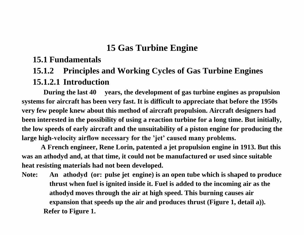
Note: An athodyd (or: pulse jet engine) is an open tube which is shaped to produce
thrust when fuel is ignited inside it. Fuel is added to the incoming air as the
athodyd moves through the air at high speed. This burning causes air
expansion that speeds up the air and produces thrust (Figure 1, detail a)).
Refer to Figure 1.
a) Lorin’s jet engine
Figure 1 Principle of Jet Engines
Secondly, jet propulsion would have been extremely inefficient at the low speeds
of early aircraft. However, today’s modern ram jet is very similar to Lorin’s conception.
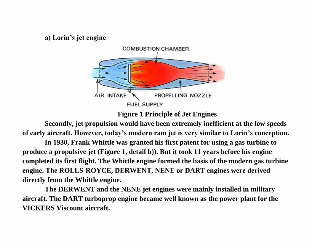
In 1930, Frank Whittle was granted his first patent for using a gas turbine to
produce a propulsive jet (Figure 1, detail b)). But it took 11 years before his engine
completed its first flight. The Whittle engine formed the basis of the modern gas turbine
engine. The ROLLS-ROYCE, DERWENT, NENE or DART engines were derived
directly from the Whittle engine.
The DERWENT and the NENE jet engines were mainly installed in military
aircraft. The DART turboprop engine became well known as the power plant for the
VICKERS Viscount aircraft.
b) Whittle-type turbojet engine
Figure 1 Principle of Jet Engines
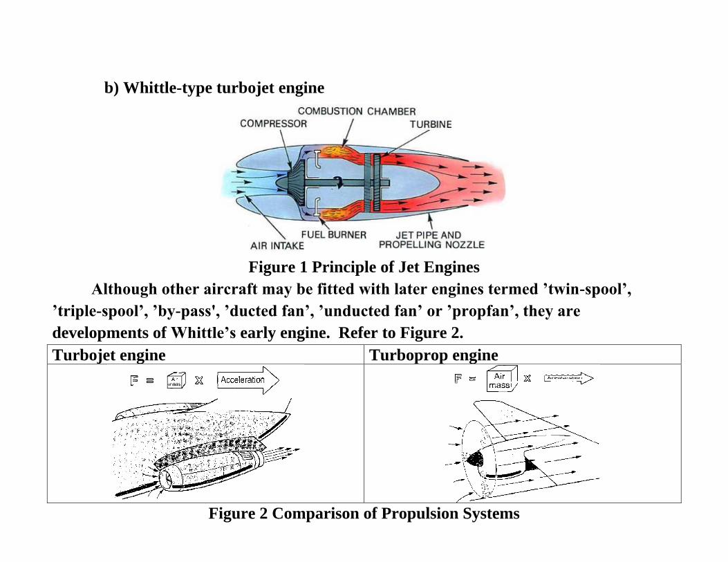
Although other aircraft may be fitted with later engines termed ’twin-spool’,
’triple-spool’, ’by-pass', ’ducted fan’, ’unducted fan’ or ’propfan’, they are
developments of Whittle’s early engine. Refer to Figure 2.
Turbojet engine Turboprop engine
Figure 2 Comparison of Propulsion Systems
Although the jet engine appears to be very different from a piston engine with a
propeller, it applies the same basic principle to produce propulsion. Both propel the
aircraft solely by moving a large volume of air rearwards.
Although today's jet propulsion is popularly linked with the gas turbine engine,
there are other types of jet-propelled engines, such as the ram jet, the pulse jet, the
rocket, the turbo-ram jet and the turbo-rocket.
15.1.2.2 Principles of Jet Propulsion
Jet propulsion is a practical application of Sir Isaac Newton's third law of motion
which states that
‘for every force acting on a body there is an opposite and equal reaction’.
For aircraft propulsion, the ’body' is atmospheric air that is caused to accelerate
as it passes through the engine. The force required to cause this acceleration has an
equal effect in the opposite direction, i.e. it acts on the components producing the
acceleration.
A jet engine produces thrust in a way similar to the piston engine/propeller
combination. Both propel the aircraft by moving a large volume of air backwards: one
in the form of a large air slipstream at comparatively low speed and the other in the
form of a jet of gas at very high speed.
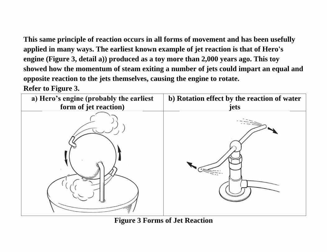
This same principle of reaction occurs in all forms of movement and has been usefully
applied in many ways. The earliest known example of jet reaction is that of Hero's
engine (Figure 3, detail a)) produced as a toy more than 2,000 years ago. This toy
showed how the momentum of steam exiting a number of jets could impart an equal and
opposite reaction to the jets themselves, causing the engine to rotate.
Refer to Figure 3.
a) Hero’s engine (probably the earliest
form of jet reaction)
b) Rotation effect by the reaction of water
jets
Figure 3 Forms of Jet Reaction
The whirling garden sprinkler (Figure 3, detail b)) is a more practical example of
this principle: its mechanism rotates due to the reaction to the water jets. The high-
pressure jets of modern fire-fighting equipment are another example of ‘jet reaction’:
due to the reaction of the water jet, the hose cannot be held or controlled by one single
fireman. Perhaps the simplest illustration of this principle is a toy balloon which, when
the air or gas is released, rushes rapidly away in the direction opposite to the jet.
Jet reaction is definitely an internal phenomenon and does not result from the
pressure of the jet on the atmosphere. In fact, the jet propulsion engine, whether rocket,
athodyd or turbojet, is a piece of equipment designed to accelerate a stream of air or gas
and to expel it at high velocity.
There are, of course, a number of ways of doing this. But in all instances, the
resultant reaction (or: thrust) exerted on the engine is proportional to the mass or
weight of air expelled by the engine and to the velocity change imparted to it.
In other words, the same thrust can be provided
□ either by giving a large mass of air a little velocity increase
□ or by giving a small mass of air a large velocity increase.
In practice, the former is preferred, since by lowering the jet velocity relative to
the atmosphere a higher propulsive efficiency is obtained.
15.1.2.3 Types of Jet Engine according to Jet Propulsion Methods
The types of jet engine, whether ram jet, pulse jet, rocket, gas turbine, turbo-ram
jet or turbo-rocket, differ only in the way in which the 'thrust provider’ (or: engine)
supplies and converts the energy into power for flight.
The ramjet engine (Figure 4, detail a)) is an athodyd (or aero-thermodynamic
duct). It has no major rotating parts and consists of a duct with a divergent entry and a
convergent or convergent/divergent exit. Refer to Figure 4.
a) Ram jet engine
Figure 4 Basic Methods of Jet Propulsion
When forward motion is imparted to it by an external source, air is forced into
the air intake. Here, it loses velocity (or: kinetic energy) and increases its pressure (or:
potential energy) as it passes through the diverging duct. Then, the total energy is
increased by the combustion of fuel. Finally, the expanding gases are expelled to the
atmosphere through the outlet duct.
A ram jet is often used as a power plant for missiles and target vehicles. But it is
unsuitable as an aircraft power plant because it requires forward motion before any
thrust can be produced.
b) Pulse jet engine
The pulse jet engine (Figure 4, detail b)) uses the principle of intermittent
combustion. Unlike the ram jet, it can be run at a static condition. The engine is formed
by an aerodynamic duct similar to the ramjet. But, due to the higher pressures involved,
it is of more robust construction. The duct inlet has a series of inlet ‘valves’ that are
spring-loaded in the 'open' position.
Air drawn in through the open valves passes into the combustion chamber and is
heated by the burning of fuel injected into the chamber.
Figure 4 Basic Methods of Jet Propulsion
The resulting expansion causes a rise in pressure, forcing the valves to close and
the expanding gases are then ejected rearwards. A depression created by the exhausting
gases allows the valves to open again and the cycle is repeated.
The pulse jet is unsuitable as an aircraft power plant because it has the high fuel
consumption and is unable to reach the performance level of the modern gas turbine
engine.
c) Rocket engine
Although a rocket engine (Figure 4, detail c)) is a jet engine, there is one major
difference: it does not use atmospheric air as the propulsive stream. Instead, it produces
its own propelling medium by the combustion of liquid or chemically decomposed fuel
with oxygen. It is able to operate outside the earth’s atmosphere.
Figure 4 Basic Methods of Jet Propulsion
d) Gas Turbine Engine
The application of the gas turbine to jet propulsion has overcome the inherent
weakness of the rocket and the athodyd: a means of producing thrust at low speeds was
provided by the introduction of a turbine-driven compressor.
The turbojet engine draws air from the atmosphere. After compressing and
heating it (a process that occurs in all heat engines) the energy and momentum, given to
the air, forces it out of the propelling nozzle at a velocity of up to 2,000 feet per second
(approx. 610 m/s or 2,200 km/h). On its way through the engine, the air gives up some of
its energy and momentum to drive the turbine that powers the compressor.
The mechanical arrangement of the gas turbine engine is simple. It consists of only
2 main rotating parts (a compressor and a turbine) and one or a number of combustion
chambers.
Note: The mechanical arrangements of various types of gas turbine engine are
shown in Figures 5 to 7.
a) Double-entry single-stage centrifugal turbojet engine
b) Single-entry 2-stage centrifugal turboprop engine
c) Twin-spool axial flow turboprop engine
Figure 5 Arrangement of Gas Turbine Engines (I)
a) Single-spool axial flow turbojet engine
b) Twin-spoot turboshaft engine (with free-power turbine)
Figure 6 Arrangement of Gas Turbine Engines (II)
a) Twin-spool by-pass turbojet engine (low by-pass ratio)
b) Triple-spool front fan turbojet engine (high by-pass ratio)
Propfan concept
c) Contra-rotating fan concept (high by-pass ratio)
Figure 7 Arrangement of Gas Turbine Engines (III)
This simplicity, however, does not apply to all aspects of the engine: the
thermodynamic and aerodynamic aspects are quite complex. They result from:
□ the high operating temperatures of the combustion chamber and the turbine
□ the effects of varying flows across the compressor and the turbine blades
□ the design of the exhaust system through which the gases are ejected to form
the propulsive jet.
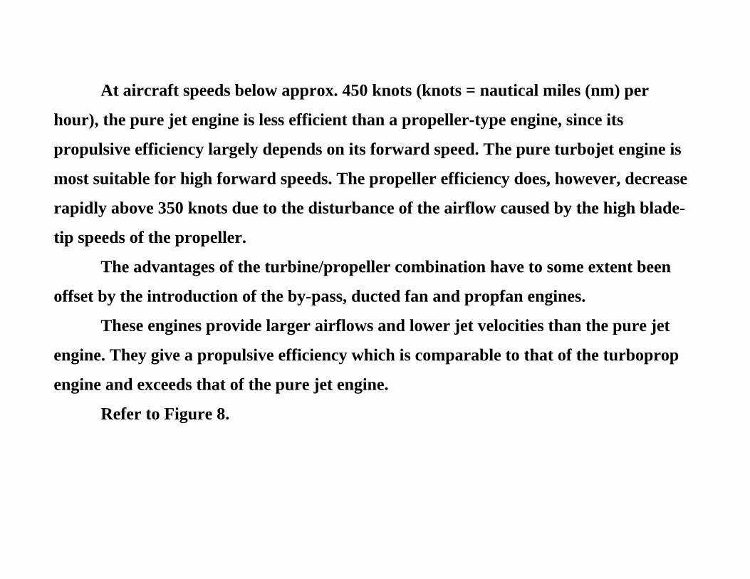
At aircraft speeds below approx. 450 knots (knots = nautical miles (nm) per
hour), the pure jet engine is less efficient than a propeller-type engine, since its
propulsive efficiency largely depends on its forward speed. The pure turbojet engine is
most suitable for high forward speeds. The propeller efficiency does, however, decrease
rapidly above 350 knots due to the disturbance of the airflow caused by the high blade-
tip speeds of the propeller.
The advantages of the turbine/propeller combination have to some extent been
offset by the introduction of the by-pass, ducted fan and propfan engines.
These engines provide larger airflows and lower jet velocities than the pure jet
engine. They give a propulsive efficiency which is comparable to that of the turboprop
engine and exceeds that of the pure jet engine.
Refer to Figure 8.
Figure 8 Comparative Efficiencies
Turboshaft Engine
A gas turbine engine that delivers power through a shaft to operate something
other than a propeller is referred to as a turboshaft engine. These are widely used in
such industrial applications as electric power generating plants and surface
transportation systems, while in aviation, turboshaft engines are used to power many
modern helicopters. Refer to Figure 9.
a) Power conversion free turbine
b) An example of a free turbine engine that has been adapted for both turboprop
and turboshaft applications
Figure 9 Free Turbine Engine
The turboshaft power take-off may be coupled to and driven directly by the
turbine that drives the compressor, but it is more likely to be driver by a turbine of its
own. Engines using a separate turbine for the power take-off are called 'free turbine
engines’ or ’free-power turbine-type turboshaft engines’.
A free turbine turboshaft engine has two major sections, the gas generator and
the free turbine section. The function of the gas generator is to produce the required
energy to drive the free turbine system and it extracts about two third of the energy
available from the combustion process leaving the other one third to drive the free-
power turbine.
The turbo-ram jet engine (Figure 10, detail a)) combines the turbojet engine
(which can be used for speeds up to Mach 3) with the ram jet engine, which shows good
performance at high Mach numbers.
The engine is surrounded by a duct that has a variable intake at the front and an
afterburner jet pipe with a variable nozzle at the rear.
During take-off and acceleration, the engine works like a conventional turbojet
with afterburner. At other flight conditions up to Mach 3, the afterburner is
inoperative. As the aircraft accelerates beyond Mach 3, the turbojet is shut down and
the intake air is diverted by guide vanes from the compressor. It is ducted straight into
the afterburning jet pipe, which now works as a ram-jet combustion chamber.
This engine is suitable for an aircraft which requires high-speed and sustained-
high-Mach-number cruise conditions.
Refer to Figure 10.
a) Turbo-ram jet engine
Turbo-rocket Engine
The turbo-rocket engine (Figure 10, detail b)) is an alternative to the turbo-ram
jet. However, there is one major difference; it carries its own oxygen to provide
combustion.
b) Turbo-rocket engine
Figure 10 Schematic Cross-section of a Turbo-ram and a Rocket Engine
The engine has a low-pressure compressor driven by a mufti-stage turbine. The
power required to drive the turbine is derived from combustion of kerosine and liquid
oxygen in a rocket-type combustion chamber. Since the gas temperature is approx.
3,500 0C, additional fuel is sprayed into the combustion chamber for cooling purposes
before the gas enters the turbine. This fuel-rich mixture (gas) is then diluted with air
from the compressor. The surplus fuel is burnt in a conventional afterburning system.
Although the engine is smaller and lighter than the turbo-ram jet, it has a higher
fuel consumption. This makes it more suitable for being used in an interceptor or space-
launcher type of aircraft that requires high speed, high altitude performance and
(normally) has a flight profile which is entirely accelerative and of short duration.