59
Piping system in Building by Asst. Prof. Channarong Asavatesanupap Department of Mechanical Engineering Faculty of Engineering Thammasat University

Piping systemin
Building
by
Asst. Prof. Channarong AsavatesanupapDepartment of Mechanical Engineering
Faculty of EngineeringThammasat University

Building piping2
Piping is a system of pipes used to convey fluids (liquids and gases) from one
location to another. It includes pipe, fittings, valves, and other piping components

Water distribution3
City water supply is distributed through municipal street mains. There are large
pipes that usually run underground below the streets. The water flows under
pressure that must be great enough to overcome the frictional resistance and static
pressure of the distribution system.
Upfeed distribution
When water is fed to fixtures in a building by the incoming pressure of water , it is
called upfeed distribution. For medium-size buildings, additional pumps have to
be installed to increase pressure.
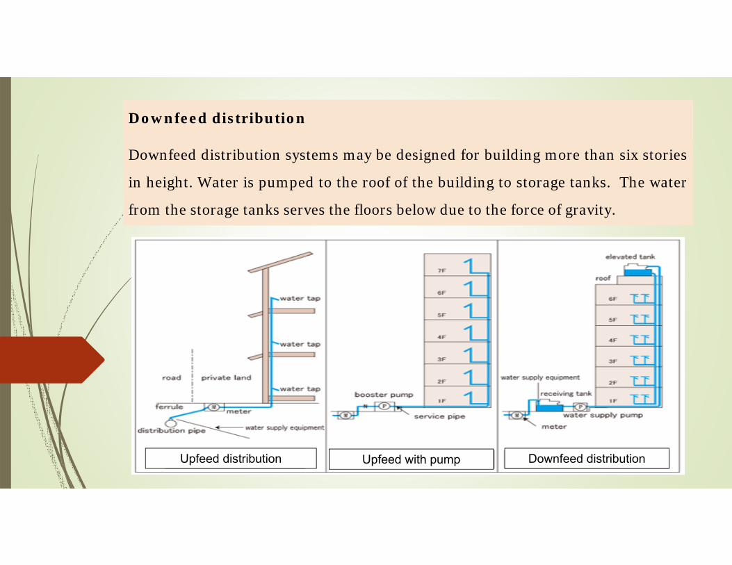
Downfeed distribution
Downfeed distribution systems may be designed for building more than six stories
in height. Water is pumped to the roof of the building to storage tanks. The water
from the storage tanks serves the floors below due to the force of gravity.
Upfeed distribution Upfeed with pump Downfeed distribution

Supply piping materials5
Water pipes and fittings may be of brass, black steel, copper, galvanized steel,
or plastic. However, the specific type of materials may be used for each particular
piping system.
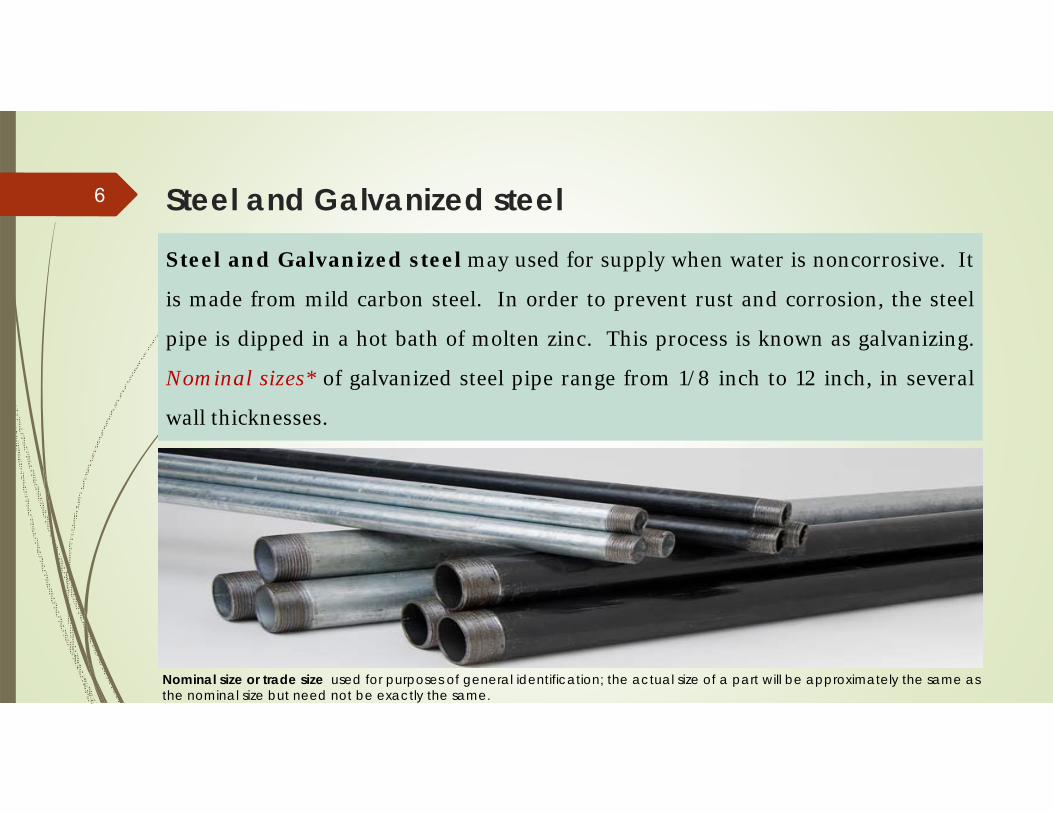
Steel and Galvanized steel6
Steel and Galvanized steel may used for supply when water is noncorrosive. It
is made from mild carbon steel. In order to prevent rust and corrosion, the steel
pipe is dipped in a hot bath of molten zinc. This process is known as galvanizing.
Nominal sizes* of galvanized steel pipe range from 1/8 inch to 12 inch, in several
wall thicknesses.
Nominal size or trade size used for purposes of general identification; the actual size of a part will be approximately the same as the nominal size but need not be exactly the same.

The pipe wall thickness is usually described using terms Schedule 40, for standard wall and Schedule 80, for extra strong wall. Schedule 40 is normally used for plumbing applications.

Plastic8
Plastic pipes are produced from synthetic resins derived from fossil fuels. Four
types of plastics are commonly used for plumbing pipes and fittings: (1) polyvinyl
chloride (PVC), (2) chlorinated polyvinyl chloride (CPVC), (3) acrylonitrile
butadiene styrene (ABS) and (4) polyethylene (PE).

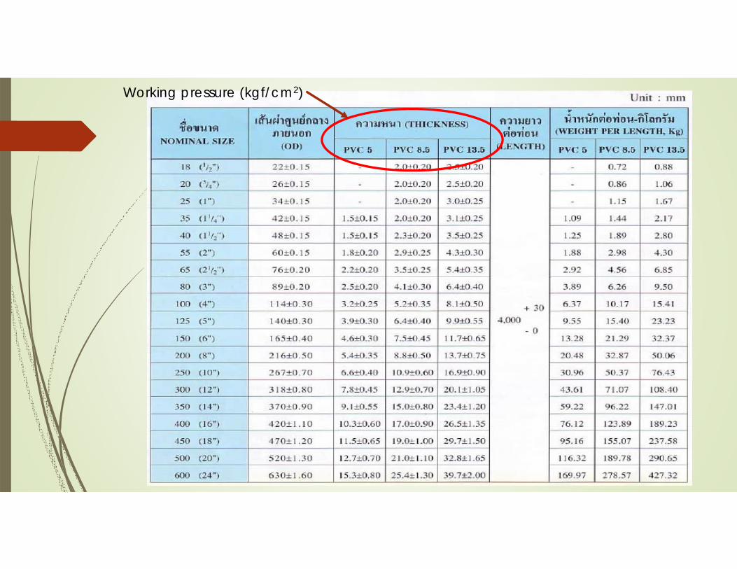
Working pressure (kgf/cm2)
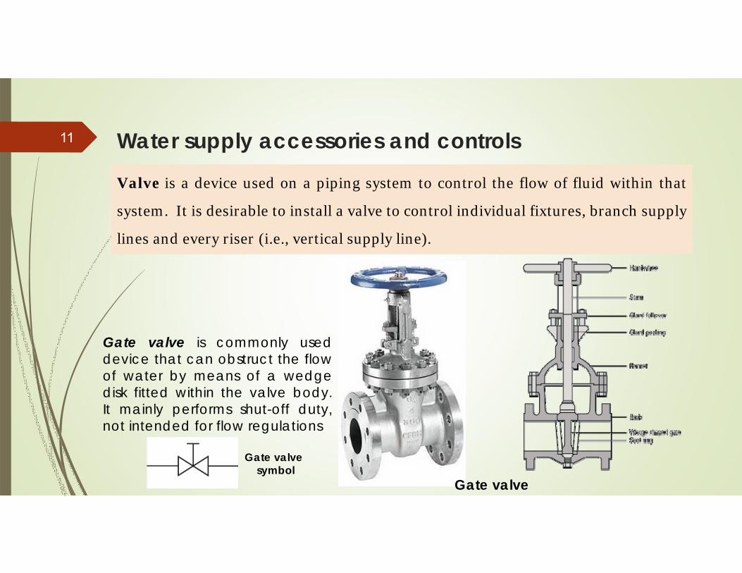
Water supply accessories and controls11
Valve is a device used on a piping system to control the flow of fluid within that
system. It is desirable to install a valve to control individual fixtures, branch supply
lines and every riser (i.e., vertical supply line).
Gate valve
Gate valve is commonly used device that can obstruct the flow of water by means of a wedge disk fitted within the valve body. It mainly performs shut-off duty, not intended for flow regulations
Gate valve symbol

Globe valve is installed when it is necessary to regulate the flow of water. It is a compression-type valve that controls the flow of water by means of a circular disk in stalled within the valve body. The globe valve has small ports, an “S” flow pattern, and relatively high pressure drop.
Globe valve symbol

Check valve is a device that prevents the flow of water in a direction reverse to the normal flow. It is used to direct the flow of water in only one direction. Any reversal flow closes the valve.
Swing-type Lift-type
Check valve symbol

Ball valve controls the water by means of a rotating ball with a cylindrical hole through its center. When the hole is aligned with the water flow, the water flow freely through the valve. It is usually used in pipes smaller than 3 inches in size.
Ball valve symbol
Rotating ball

Butterfly valve has a rotating disk that controls the water flow. When fully open, the disk is aligned with the water flow. To close the disk is rotated at a right angle so that it fully blocks the flow. They are used mostly on pipes that are 3 inches or larger in size.
Butterfly valve symbol

Water hammer arrestor When a water supply valve or a fixture in a supply system is closed quickly, the force exerted by the fast flowing water causes the pipe to shake and rattle. This is known as water hammer. It can be prevented by closing the valve slowly or be controlled by using a “water hammer arrestor”.

Pipe expansion joint is an assembly designed to safely absorb the heat-induced expansion and contraction of construction materials, to absorb vibration, to hold parts together, or to allow movement.
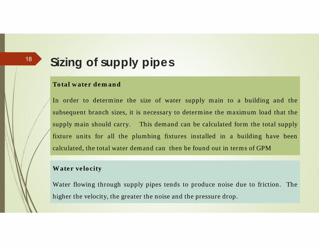
Sizing of supply pipes18
Total water demand
In order to determine the size of water supply main to a building and the
subsequent branch sizes, it is necessary to determine the maximum load that the
supply main should carry. This demand can be calculated form the total supply
fixture units for all the plumbing fixtures installed in a building have been
calculated, the total water demand can then be found out in terms of GPM
Water velocity
Water flowing through supply pipes tends to produce noise due to friction. The
higher the velocity, the greater the noise and the pressure drop.
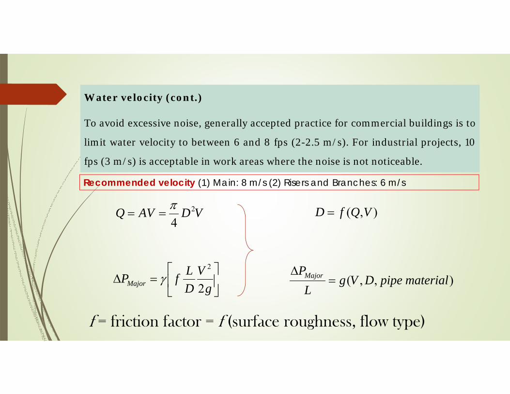
Water velocity (cont.)
To avoid excessive noise, generally accepted practice for commercial buildings is to
limit water velocity to between 6 and 8 fps (2-2.5 m/s). For industrial projects, 10
fps (3 m/s) is acceptable in work areas where the noise is not noticeable.
gV
DLfPMajor 2
2
VDAVQ 2
4
),,( materialpipeDVgL
PMajor
),( VQfD
f = friction factor = f (surface roughness, flow type)
Recommended velocity (1) Main: 8 m/s (2) Risers and Branches: 6 m/s
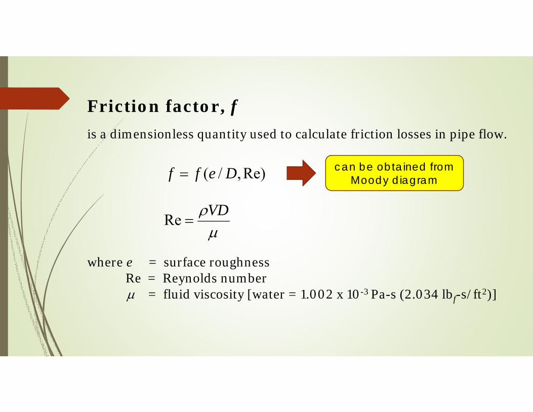
Friction factor, f is a dimensionless quantity used to calculate friction losses in pipe flow.
where e = surface roughnessRe = Reynolds number = fluid viscosity [water = 1.002 x 10⁻³ Pa-s (2.034 lbf-s/ft2)]
Re),/( Deff
VD
Re
can be obtained from Moody diagram

Moody diagram
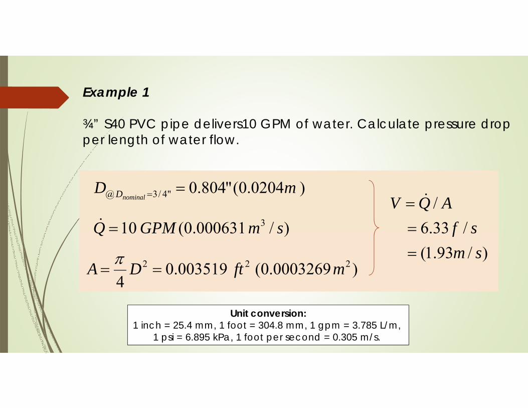
Example 1
¾” S40 PVC pipe delivers10 GPM of water. Calculate pressure drop per length of water flow.
Unit conversion:1 inch = 25.4 mm, 1 foot = 304.8 mm, 1 gpm = 3.785 L/m,
1 psi = 6.895 kPa, 1 foot per second = 0.305 m/s.
)0204.0("804.0"4/3@ mDnominalD
)/000631.0(10 3 smGPMQ
)0003269.0(003519.04
222 mftDA )/93.1(
/33.6/
smsf
AQV

Example 1 (cont.)
200,39Re
VD
De / Smooth pipe
039.0f(from Moody diagram)
TurbulentTransitionLaminar
VD
40004000Re2300
2300Re

Moody diagram
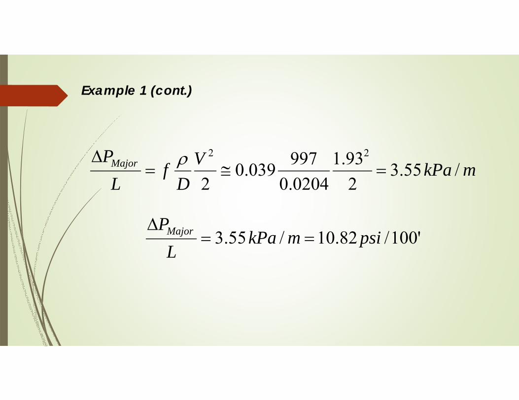
Example 1 (cont.)
mkPaVD
fL
PMajor /55.3293.1
0204.0997039.0
2
22
'100/82.10/55.3 psimkPaL
PMajor

Friction loss diagramfor fairly smooth pipe flow
10 GPM
(e.g. pvc, steel pipe)

Friction loss diagramfor rough pipe flow(e.g. old cast iron , concrete pipe)

Friction loss diagramfor Fairly rough pipe flow
(e.g. New cast iron pipe)
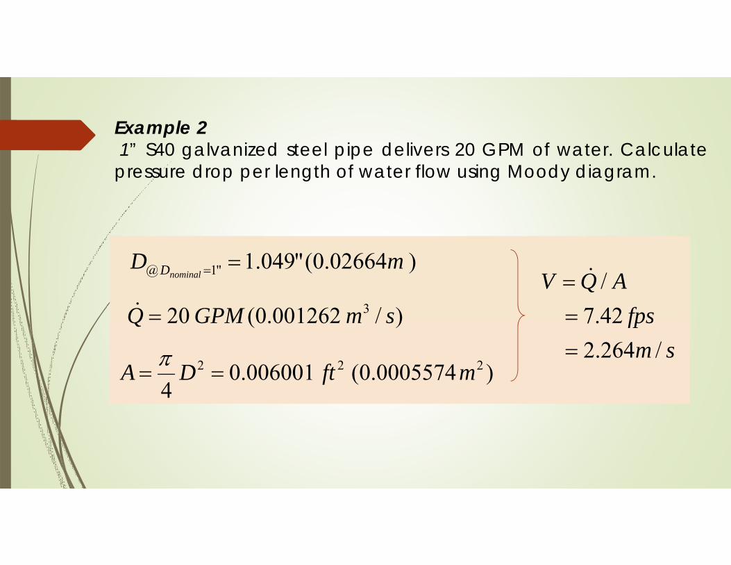
Example 21” S40 galvanized steel pipe delivers 20 GPM of water. Calculate pressure drop per length of water flow using Moody diagram.
)02664.0("049.1"1@ mDnominalD
)/001262.0(20 3 smGPMQ
)0005574.0(006001.04
222 mftDA sm
fpsAQV
/264.242.7/
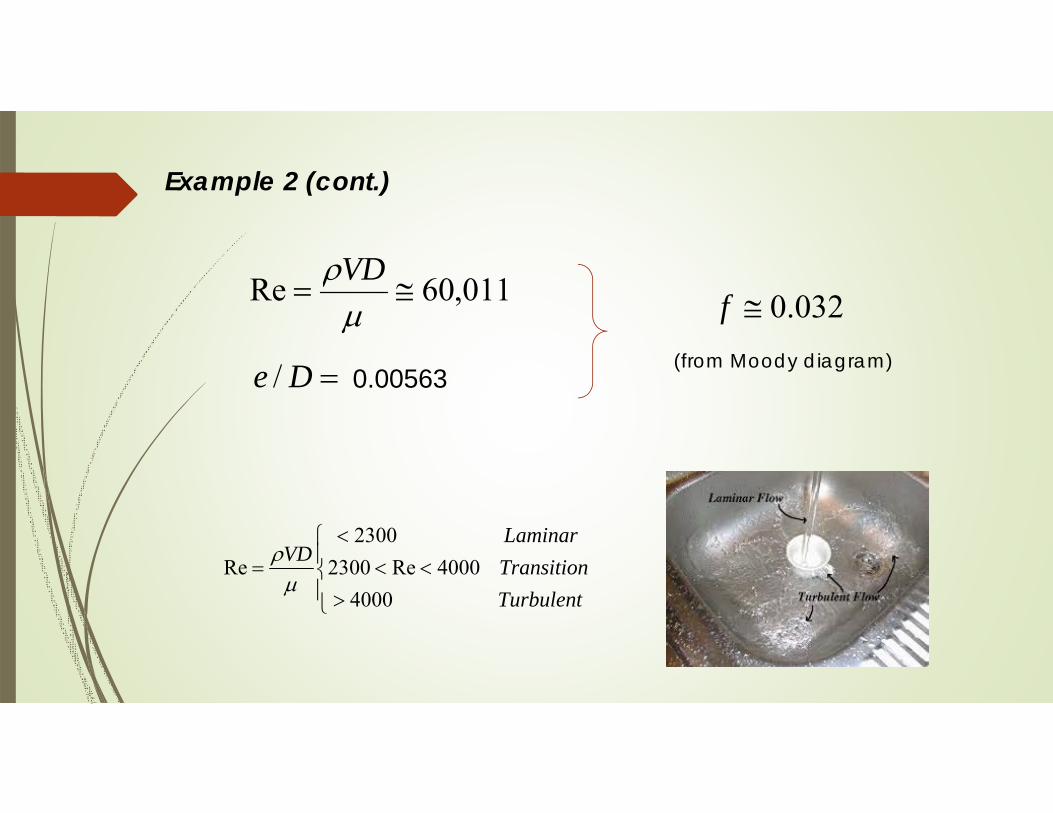
Example 2 (cont.)
011,60Re
VD
De / 0.00563
032.0f(from Moody diagram)
TurbulentTransitionLaminar
VD
40004000Re2300
2300Re

Moody diagram

Example 2 (cont.)
mkPaVD
fL
PMajor /07.32264.2
02664.0997032.0
2
22
'100/26.9/55.3 psimkPaL
PMajor

Example 3Determine the diameter of galvanized steel pipe needed to deliver water at a flow rate of 10 GPM and a velocity of 8 fps


Plumbing system design

Plumbing fixtures
is an exchangeable device which can be connected to a plumbing system to deliver and drain water. The most common plumbing fixtures are: bathtubs, drinking fountains, kitchen sinks, showers, channel drains, and lavatories.

Supply Fixture Units (SFU) Demand for water by a plumbing fixture varies according to its type and the occupancy category of the building in which it is installed.
Drainage Fixture Units (DFU) is a measure of the probable discharge into the drainage system by various types of plumbing fixtures.
Minimum supply pressure is a certain demand of water pressure for each fixture.
Fixture Unit is a design factor which represents a probable flowrate of a plumbing fixture. The number of fixture units depends on the volume of water required, the average duration of a single use, and the number of uses per unit time.

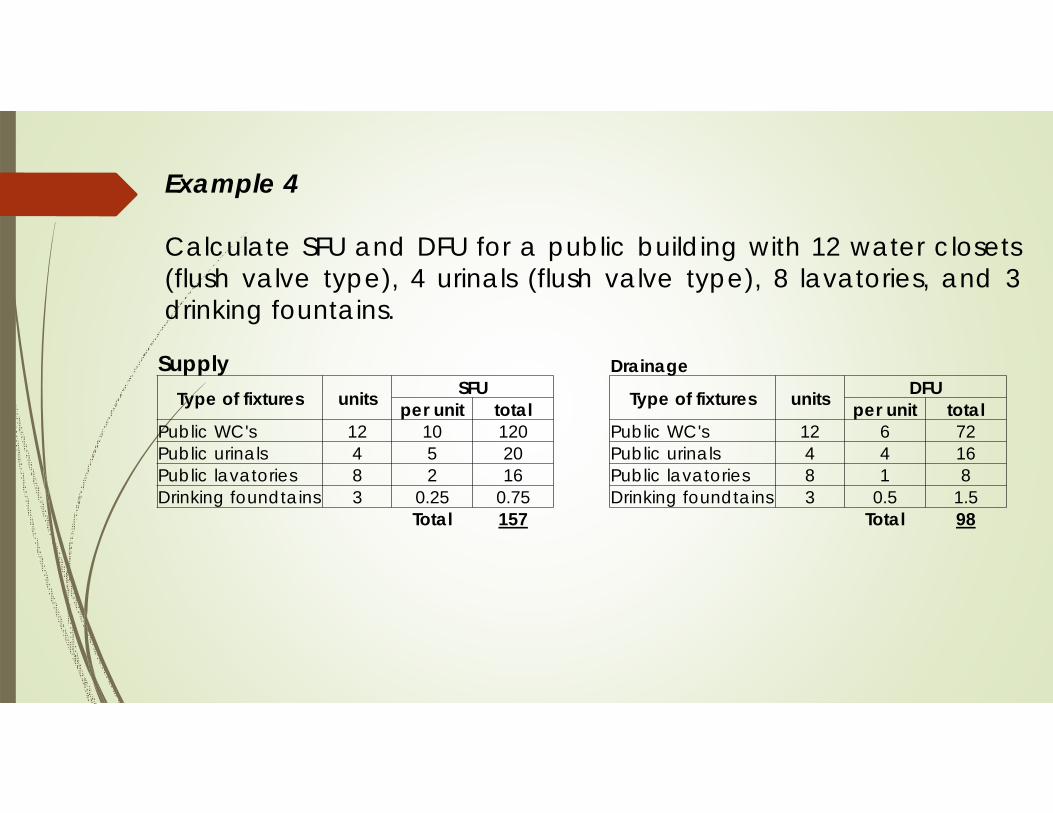
Example 4
Calculate SFU and DFU for a public building with 12 water closets (flush valve type), 4 urinals (flush valve type), 8 lavatories, and 3 drinking fountains.
SupplyType of fixtures units SFU
per unit totalPublic WC's 12 10 120Public urinals 4 5 20Public lavatories 8 2 16Drinking foundtains 3 0.25 0.75
Total 157
Drainage
Type of fixtures units DFUper unit total
Public WC's 12 6 72Public urinals 4 4 16Public lavatories 8 1 8Drinking foundtains 3 0.5 1.5
Total 98
Supply GPM
The Supply Fixture Units - FSU - are used to determine the water demand in water supply systems. One FSU for a single unit corresponds to one GPM.
1 SFU = 1 GPM
This conversion can only be used for one or a few fixtures. When the total amount for many fixtures are added up, the number must be compensated due to the intermittent use of the fixtures. This is normal taken care of in the figures or tables available for sizing supply pipe lines.

Total SFU to water supply demand in gallons per minute (supply GPM)1 GPM = 3.79 liter/min
Note: Read solid-line curves for residential and commercial occupancies;use the dashed curves for large assembly occupancies (for examples: stadium, theater)

Source:

Example 4Select the sizes of PVC pipe for the pluming system (Tank-type WC). The main supply pipe velocity should not exceed 8 fps, and the riser and the branch velocities should not exceed 6 fps.
Main
Riser
Branch
60 SFU
30 SFU
30 SFU
1
2
34
5
6
Pipe # SFU GPM Pipe size Velocity1 120 25.9 1 1/4" <8.02 60 18.4 1" <6.03 30 14.7 1" <6.04 60 18.4 1" <6.05 30 14.7 1" <6.06 30 14.7 1" <6.0

HW#4A private building with 10 water closets (Gravity tank type), 3 urinals (flush valve type), 2 bathroom group (Gravity tank type) and 4 lavatories. Calculate (a) total supply demand (supply GPM)(b) Total pressure drop of the supply main pipe if the total length is 30 feet. (Note: Designed flow velocity should not exceed 8 fps.)
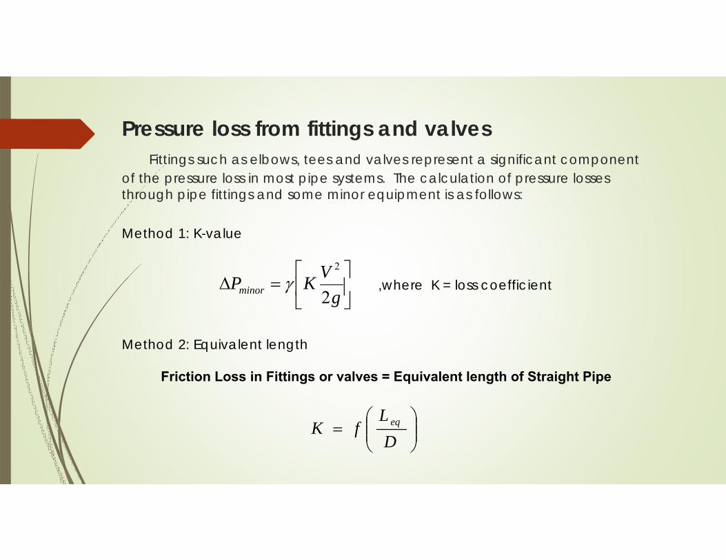
Pressure loss from fittings and valvesFittings such as elbows, tees and valves represent a significant component
of the pressure loss in most pipe systems. The calculation of pressure losses through pipe fittings and some minor equipment is as follows:
gVKPminor 2
2
,where K = loss coefficient
Method 1: K-value
Method 2: Equivalent length
Friction Loss in Fittings or valves = Equivalent length of Straight Pipe
DL
fK eq
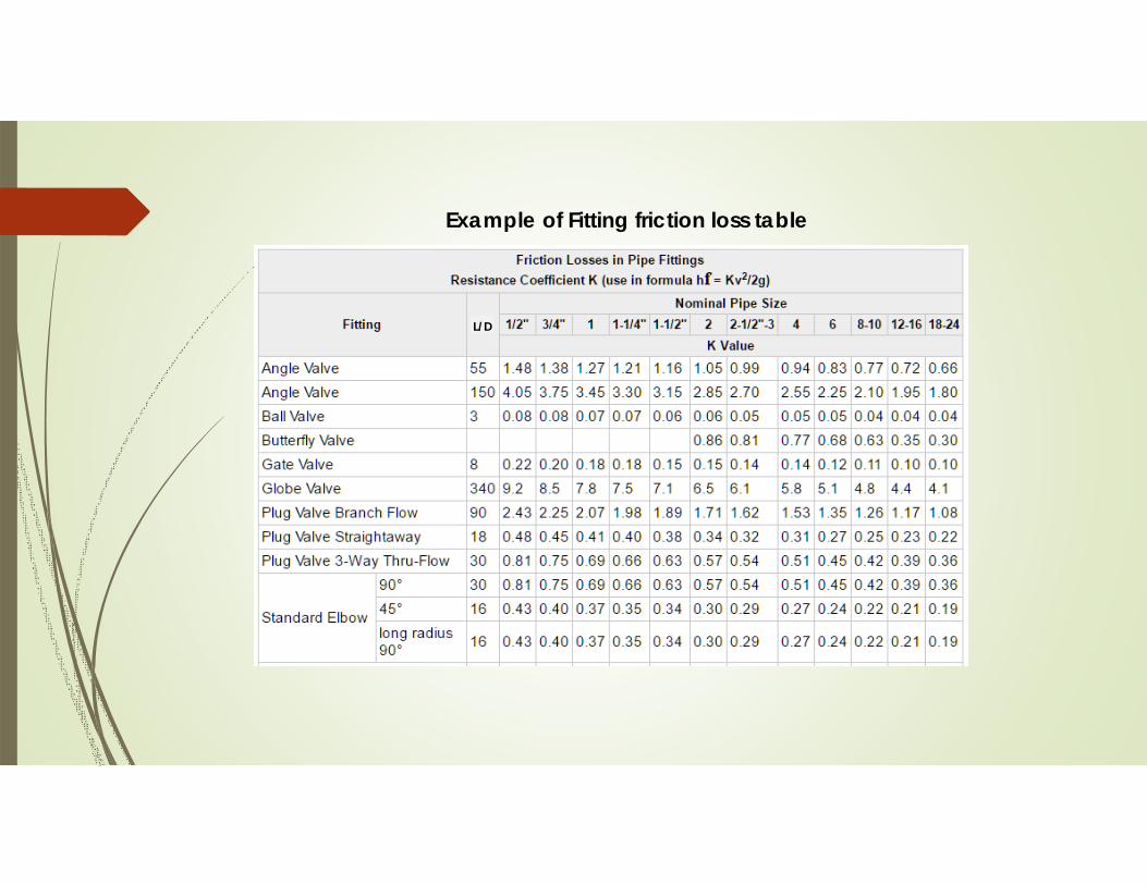
Example of Fitting friction loss table
L/D

Quick finding MethodTee Elbow
Angle valvePlug-type cock
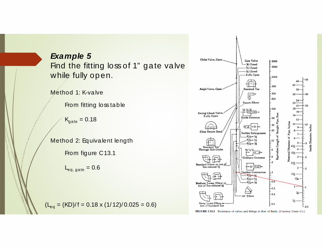
Example 5Find the fitting loss of 1” gate valve while fully open.
Method 1: K-valve
From fitting loss table
Kgate = 0.18
Method 2: Equivalent length
From figure C13.1
Leq, gate = 0.6
(Leq = (KD)/f = 0.18 x (1/12)/0.025 = 0.6)
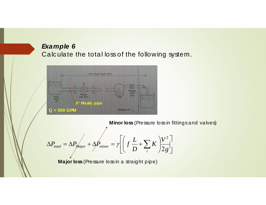
Example 6Calculate the total loss of the following system.
5” Plastic pipe
Q = 500 GPM
g
VKDLfPPP
iminorMajortotal 2
2
Major loss (Pressure loss in a straight pipe)
Minor loss (Pressure loss in fittings and valves)

Example 6 (cont.)Calculate the total loss of the following system.
No.D
(in.)f L
(ft.)K V
(fps)
LossHead (ft)
Pressure (psi)
1 Straight pipe 5 0.0256 350 - 8 21.37 9.26
2 Sharp edged exit
5 0.0256 7.5 0.5 8 0.46 0.20
3 Gate valve 5 0.0256 3 0.18 8 0.18 0.084 Check valve 5 0.0256 35 2.2 8 2.14 0.93
total 24.15 10.47
Using Moody diagram and Fig c13.1

Pump selectionis based on two parameters:
51
Flow Rate (Total water demand: GPM)
Pumps are selected for the peak flow rate. The peak flow rate is the sum of water
demands for all plumbing fixtures, i.e. the total water demand.
Total Dynamic Head (Pressure rise)
Total dynamics head of the pump is the head difference between the summation of
total head loss HL, static head loss HS, and desired discharge head HD and supply
main head HM.
TDH = HL + HS + HD – HM
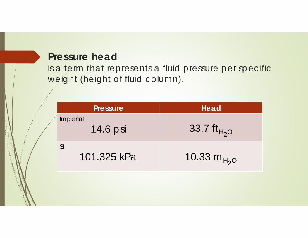
Pressure headis a term that represents a fluid pressure per specific weight (height of fluid column).
Pressure HeadImperial
14.6 psi 33.7 ftH2O
SI
101.325 kPa 10.33 mH2O
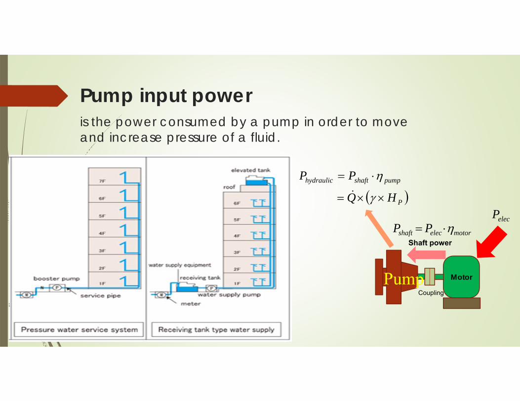
Pump input poweris the power consumed by a pump in order to move and increase pressure of a fluid.
Motor
CouplingPump
Shaft power
P
pumpshafthydraulic
HQ
PP
elecPmotorelecshaft PP

Pump input power (cont.)
pump
shaftTDHSGQP
8.9
pump
shaftTDHSGQP
13
[SI unit: kW]
[SI unit: HP]
pump
shaftTDHSGQP
3960
[Imperial unit: HP]
,where Q = GPM, TDH = ft., SG = Specific gravity (e.g. SGwater =1)
(1HP = 746 W)
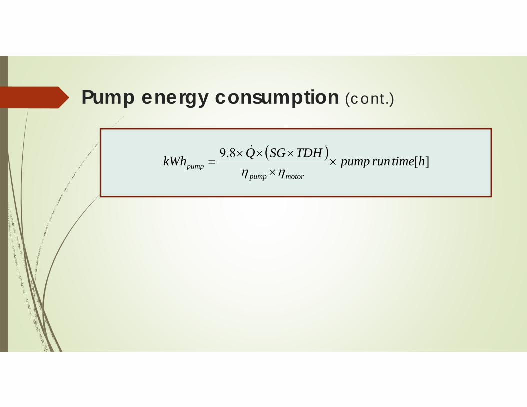
Pump energy consumption (cont.)
][8.9 htimerunpumpTDHSGQkWhmotorpump
pump
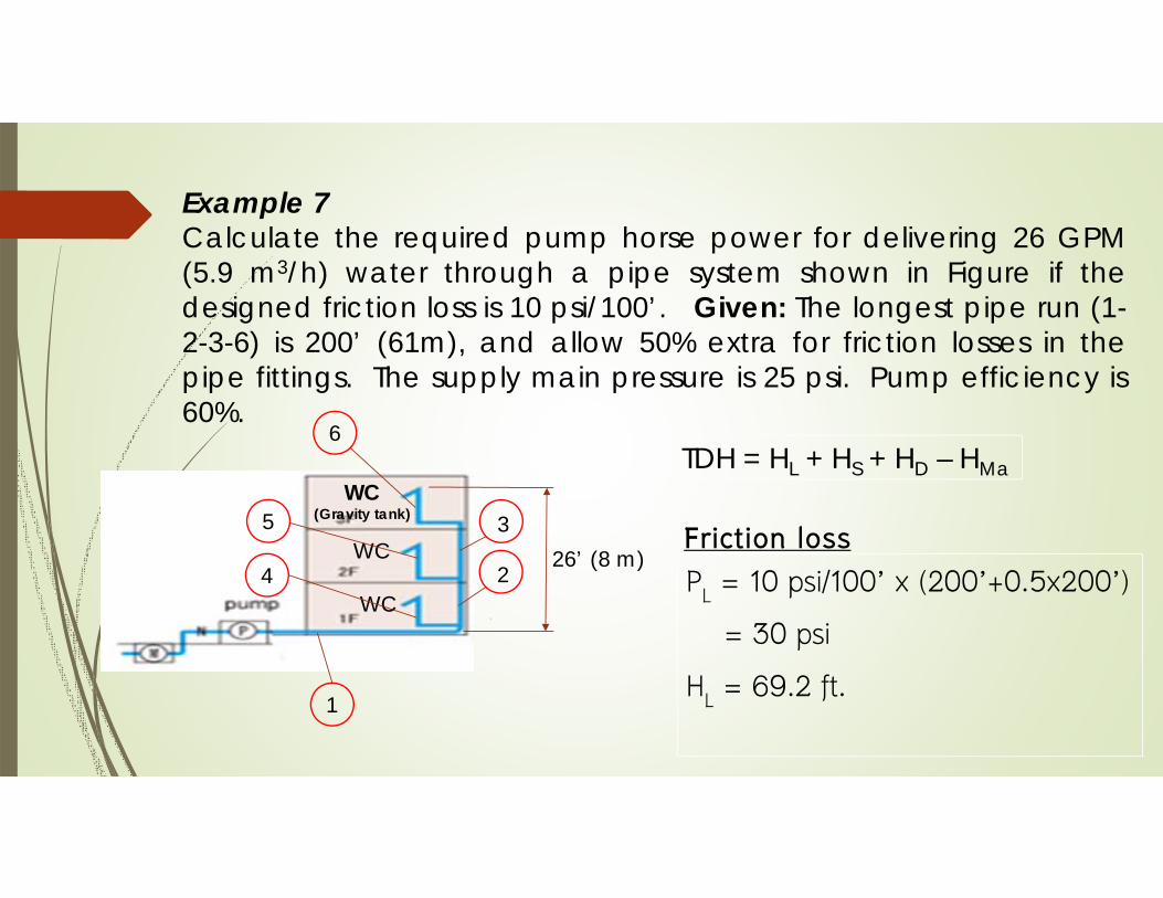
Example 7Calculate the required pump horse power for delivering 26 GPM (5.9 m3/h) water through a pipe system shown in Figure if the designed friction loss is 10 psi/100’. Given: The longest pipe run (1-2-3-6) is 200’ (61m), and allow 50% extra for friction losses in the pipe fittings. The supply main pressure is 25 psi. Pump efficiency is 60%.
WC
WC
WC(Gravity tank)
4
5
6
1
2
326’ (8 m)
TDH = HL + HS + HD – HMa
PL = 10 psi/100’ x (200’+0.5x200’)
= 30 psi
HL = 69.2 ft.
Friction loss

Example 7 (cont.)
HS = 26 ft.Static loss
PD = 10 psi (Water closet: Gravity tank)
HD = 23 ft.
Discharge loss
TDH = 69.2 + 26 + 23 – 57.6 = 60.6 ft. (18.5 m)
PM = 25 psi
HM = 57.6 ft.
Supply main pressure
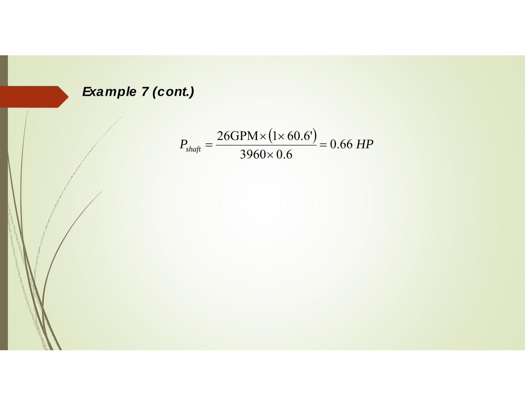
Example 7 (cont.)
HPPshaft 66.06.03960
'6.601GPM26

Final Examination
Date/Time: June 07(Wed), 2017 13:30-16:30
5 Problems:
Conditions of Examination1. Closed book
2. Calculator allowed
Good Luck !!!


