31
PETE 410 NATURAL GAS ENGINEERING Ibrahim Kocabas Petroleum Engineering Department King Fahd University of Petroleum & Minerals
| Date post: | 27-Dec-2015 |
| Category: |
Documents |
| Upload: | nicolas-vincenti-wadsworth |
| View: | 29 times |
| Download: | 0 times |

PETE 410
NATURAL GAS ENGINEERING
Ibrahim KocabasPetroleum Engineering Department
King Fahd University of Petroleum & Minerals

Natural Gas Engineering
Learning Objectives of Lecture 5:
Concepts of OGIP, gas reserves and recovery factor
Gas in place by volumetric equation Material balance equation of dry and wet
gases Decline curves for dry and wet gas
reserves

Basic concepts
Concepts: OGIP: volume of gas at time of discovery
expressed in SCF gas reserves: volume of gas that presently
exists and can be recovered economically expressed in SCF
recovery factor: ratio of initial reserves to OGIP

Methods to estimate basic quantities
The following methods are applied to estimate
OGIP: volumetric methods, MBE gas reserves: Volumetric methods, MBE,
decline curve analysis recovery factor: volumetric methods,
MBE and decline curve analysis

Estimation of Gas in Place
Volumetric methods:Voluetric methods consider the reservoir PV at intial conditions and at later conditions after some fluid production and associated pressure reduction.
Used early in the life of the reservoir before signifcant development and production

Estimation of Gas in Place
Accuracy of volumetric estimates depends on the availability of sufficient data to characterize the reservoirs’s
Areal extent Variations in net thickness and Ultimately to determine the gas bearing reservoir
PV
As more wells are drilled and more data become available the accuracy of these estimates improves

Estimation of Gas in Place
Data used to estimate the reservoir PV include Well logs Core analysis Bottom hole pressures, BHP Fluid sample analysis Well tests

Estimation of Gas in Place
The avaliable data is used to develop subsurface maps such as
Cross sectional maps help to establis reservoir areal extent and to identify reservoir discontinuities such as pinchouts, faults, gas water contacts
Contour maps are constructed with lines connecting equal elevations relative to a marker formation. They portray the geologic structure
Isopachous maps are constructed with lines of equal net gas bearing formation thickness.

Estimation of Gas in Place
With isopachous maps, the reservoir PV can be
estimated by plenimetering the areas between
isopachous lines and using an approximate volume
calculation technique. a Trapeziodal rule or b Pyramidal rule as follows
An is area enclosed by lower isopach line
An+1 is area enclosed by upper isopach line
12 nna AA
hV 113 nnnn
b AAAAh
V

Estimation of Gas in Place
For a series of successive trapezoids the total volume
Becomes
Where tave is the average thickness above the
maxumum thickness isopach line
11210 2.....222 nnn
a taveAAAAAAh
V

Estimation of Gas in Place
Given the plenimetered areas of this isopachous map of an idealized reservoir,you are asked to calculatenet reservoir volume

Estimation of Gas in Place
ftacVa 9631542312
5
ftacVb 55874*154741542
5
productive area
planimeter area* sq. in.
area acres*
ratio of areas
interval h,feet equation
ΔV ac-ft
A0 19.64 450A1 16.34 375 0.83 5 Trap. 2063A2 13.19 303 0.80 5 Trap. 1695A3 10.05 231 0.76 5 Trap. 1335
A4 6.69 154 0.67 5 Trap. 963a
A5 3.22 74 0.48 5 Pyr. 558b
A6 0.00 0 0.00 4 Pyr. 99c
6713 ac-ft
ftacVc 99743
4

Average reservoir pressure
1. Arithmetic average of well pressures (for small pressure gradients and uniform thickness)
2. Average areal pressure (large gradients and uniform thickness)
3. Average volumetric pressure(large gradients and noniniform thickness)

Average reservoir pressure
Well average pressure
Areal average pressure
Volume average pressure
n
p
p
n
i
R
1
n
i
n
ii
R
A
Ap
p
0
0
n
ii
n
iii
R
hA
hAp
p
0
0

Average reservoir pressure

Average reservoir pressure
psiapR 27434
10970
psiapR 275015760
10034143
well. Nopressure
psiadrainage area ac
p*A h,ft p*A*h A*h
1 2,750 160 440,000 20 8,800,000 3,2002 2,680 125 335,000 25 8,375,000 3,1253 2,840 190 539,600 26 1,409,600 4,9404 2,700 145 391,500 31 12,136,500 4,495
10,970 620 1,706,100 43,341,100 15,760
psiapR 2752620
1001706
well aveage
areal aveage
Volume average

Average reservoir pressure
Volume average pressure based on isobaric maps superposed on isopach maps
Same formula is valid expect we use block volumes contained between isobars and Isopachs as in the following figure.
n
ii
n
iii
R
hA
hAp
p
0
0

Average reservoir pressure

Average reservoir pressure
psiapR 28175.2579
000519726 Volume average
area acres*pressure
psiah,ft A*h p*A*h
A 25.5 2,750 25 637.5 175,313,000 D 15.1 2,750 15 226.5 62,288,000 C 50.5 2,850 25 126.5 359,813,000 D 30.2 2,850 15 453.0 129,105,000
2579.5 726,519,000

Average reservoir pressure
Volume average pressure based on isobaric maps superposed on isopach maps
Same formula is valid expect we use block volumes contained between isobars and Isopachs as in the following figure.
n
ii
n
iii
R
hA
hAp
p
0
0

Gas in place: volumetric dry gas reservoir
Assume that the PV occupied by the gas, i.e.
Vg, and water saturation remain constant during the production of the reservoir
343560 ftAhPV 3)1(43560 ftSAhV wig
SCFB
SAhG
gi
wi )1(43560

Recovery Factor: volumetric dry gas reservoir
Gas remained at abandonment is
343560 ftAhPV
3)1(43560 ftSAhV wig
SCFB
SAhG
ga
wia
)1(43560

Recovery Factor: volumetric dry gas reservoir
Produced volume at abondonment
Recovery factor is
ga
wi
gi
wiap B
SAh
B
SAhGGG
)1(43560)1(43560
ga
giap
B
B
G
GG
G
GRF
1

Recovery Factor: volumetric dry gas reservoir
Example. Given the following data calculateInitial gas in place and recovery factor for a volumetric dry gas reservoirPi=2500 psia A=1000 acresT=180 F =20%Swi=25% h=10 ftZi=0.860 Pa=500 psia Za=0.970 ?

Recovery Factor: volumetric dry gas reservoir
Home exercise. Given the following data calculate
Initial gas in place and recovery factor for a volumetric wet gas reservoirPi=2500 psia A=1000 acresT=180 F =20%Swi=25% h=10 ftPa=500 psiaAssume the same properties of example 1.8

Recovery Factor: water drive dry gas reservoir
If there is a water influx, gas remained at abandonment is
Hence, produced volume at abondonment
SCFB
SAhG
ga
waa
)1(43560
ga
wa
gi
wiap B
SAh
B
SAhGGG
)1(43560)1(43560
Recovery Factor: water drive dry gas reservoir
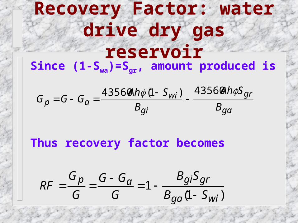
Since (1-Swa)=Sgr, amount produced is
Thus recovery factor becomes
ga
gr
gi
wiap B
SAh
B
SAhGGG
43560)1(43560
)1(1
wiga
grgiap
SB
SB
G
GG
G
GRF

Recovery Factor: water drive dry gas reservoir
Assuming that non all of the reservoir is swept by the encroaching water, the reservoir gas will be divided into two portions.
gas remaining in the portion swept by the water
trapped gas region because it was bypassed by encroaching water
Thus produced gas becomes
tvavp GEGEGG )1(

Recovery Factor: water drive dry gas reservoir In terms of PV saturations and FVFs
Thus recovery factor becomes
ga
wiv
ga
grv
gi
wip B
SAhE
B
SAhE
B
SAhG
)1(43560)1(
43560)1(43560
v
v
wi
gr
ga
giv
p
E
E
S
S
B
BE
G
GRF
1
)1(1

Recovery Factor: volumetric dry gas reservoir
Example. Given the following data calculateInitial gas in place and recovery factor for a Water drive dry gas reservoirPi=2500 psia A=1000 acresT=180 F =20%Swi=25% h=10 ftZi=0.860 Pa=750 psia Za=0.55 Sgr=0.35 Ev=100 and Ev=60%%

Recovery Factor: volumetric dry gas reservoir
Example. Given the following data calculateInitial gas in place and recovery factor for a volumetric dry gas reservoirPi=2500 psia A=1000 acresT=180 F =20%Swi=25% h=10 ftZi=0.860 Pa=500 psia Za=0.970 ?