Page 1
LED DriversA Practical Understandingfor Lighting Applications
LED DriversA Practical Understandingfor Lighting Applications
Dr. Adan Hernandez, Philips-Advance
Al Marble, Philips-Advance
Page 2
2
OutlineOutline
What is a driver?Design typesConstant current vs. constant voltageStandards/compliance to codesEnvironmental/temperature ratingsPower factor correction
Page 3
3
Typical SSL systemTypical SSL system
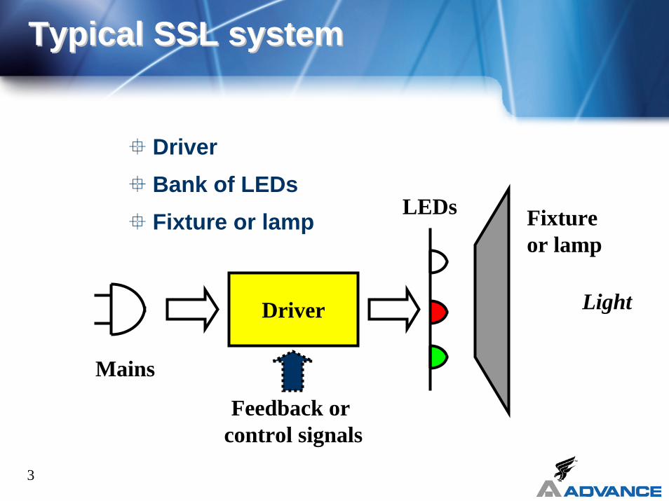
DriverBank of LEDsFixture or lamp LEDs Fixture
or lamp
Driver
Mains
Light
Feedback or control signals
Page 4
4
Purpose and FunctionPurpose and Function
“Driver” term adopted from electronic component terminologySimilar function as ballast
Processes line voltage into power usable by LED’s
Regulates and controls current to LED’s
Switch-mode electronic solutions Magnetic solutions
Page 5
5
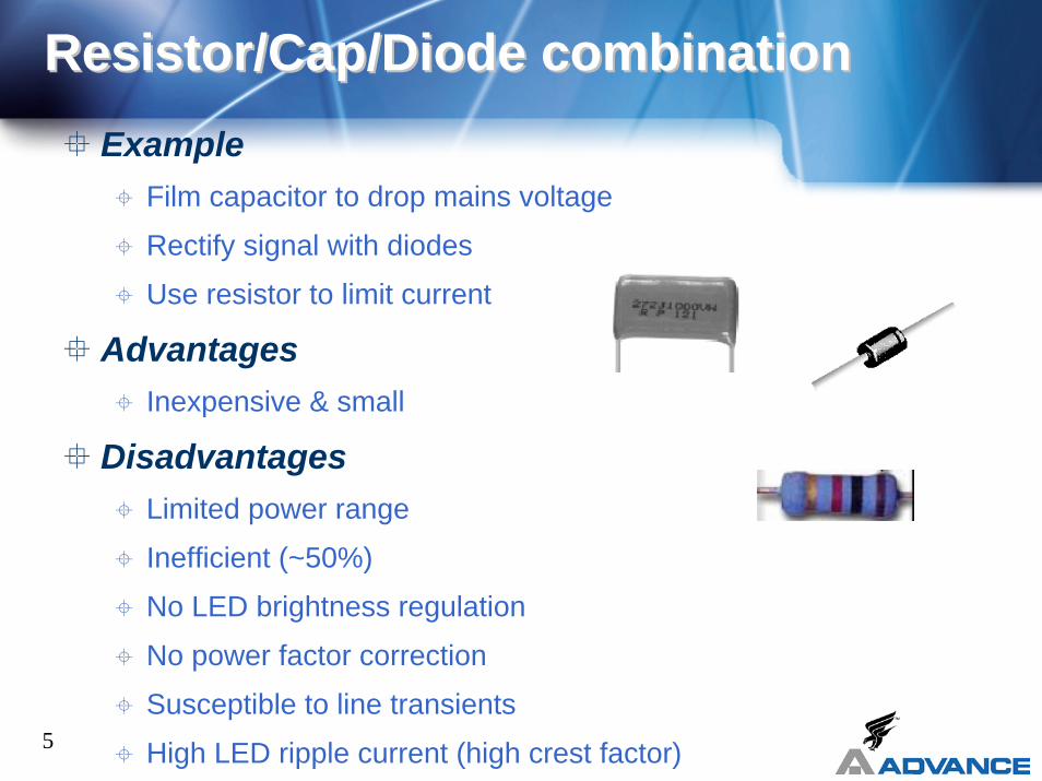
Resistor/Cap/Diode combinationResistor/Cap/Diode combinationExample
Film capacitor to drop mains voltage
Rectify signal with diodes
Use resistor to limit current
AdvantagesInexpensive & small
DisadvantagesLimited power range
Inefficient (~50%)
No LED brightness regulation
No power factor correction
Susceptible to line transients
High LED ripple current (high crest factor)
Page 6
6
Design Type: MagneticDesign Type: Magnetic
ExampleUse 60Hz step down transformer
Rectify signal with diode bridge
Use capacitor to filter ripple
AdvantagesLow cost (?)
DisadvantagesLimited LED current regulation
Weight & Size
Low power factor
Power de-rating
Safety concerns
Page 7
7
Design Type: SwitchDesign Type: Switch--Mode Electronic Mode Electronic
ExampleFlyback converter
PF correction IC
MOSFET or BJT switch
AdvantagesHigh efficiency
Small size & weight
Power factor correction
Regulation & Controllability
DisadvantagesHigher cost (?)
Page 8
8
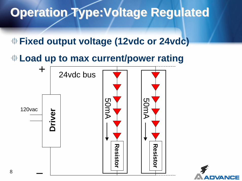
Operation Type:Voltage RegulatedOperation Type:Voltage Regulated
Fixed output voltage (12vdc or 24vdc)
Load up to max current/power rating+
_
Driv
er
24vdc bus
50mA
Resistor
50mA
Resistor
120vac
Page 9
9
Operation Type:Voltage RegulatedOperation Type:Voltage Regulated
Advantage
Flexibility to connect variable LED load
Simple application
Disadvantage
More parts on LED array (current limiting resistors)
Not as energy efficient
Page 10
10
Operation Type: Current RegulatedOperation Type: Current Regulated
Fixed output current (e.g., 350mA)
Add load in series up to max output voltage +
_
Xita
nium
350mA
120vac
Page 11
11
Operation Type: Current RegulatedOperation Type: Current Regulated
Advantage
Greater energy efficiency (no current limiting resistors)
Disadvantage
Less flexibility in connecting variable number of LEDs
In general,
Constant Current for high flux LEDs and,
Constant Voltage for low flux LEDs
Page 12
12
Standards/Compliance to CodesStandards/Compliance to Codes
UL “Recognized Component” status
UL not providing “Listing” for LED drivers
Key: Listing in Sign Accessory Manual (SAM)
Confusing to field inspectors
UL Class 2 (defined in UL 1310)
Load voltage <30vdc, load current <5 amps
Short circuit protection: Secondary fusing or inherent power limitation
Implies conduit on secondary not required, but many local codes require anyways
Page 13
13
Environmental/Temperature RatingsEnvironmental/Temperature Ratings
Environmental ratings
Dry location: Protected from any moisture
Damp location: Suitable for self-contained signs/raceway installation
Mount ½-inch from bottom of enclosure!
Referred in UL 935 as “Outdoor Type II”
Wet location: Weatherproof housing/enclosure
Temperature ratings
Case ratings used by OEMs, impractical for field use
Look for ambient rating for sign application
Page 14
14
Power Factor CorrectionPower Factor Correction
Best understood by thinking of it as “current factor correction”
Power factor corrected drivers have lower input amperage draw
Lighting industry standards
High power factor (HPF): >90%
Normal power factor (NPF): <90…60% typical
Page 15
15
Power Factor CorrectionPower Factor Correction
Concept:
For a given LED load . . . HPF driver draws less input amps than NPF driver
Power factor correction is not related to:Wattage
Power supply losses (efficiency)
How the LEDs are driven
Page 16
16
Power Factor CorrectionPower Factor Correction
60 Watt HPF Driver
60 Watt NPF Driver
Driver
LED Load:60 watt 5 amp 12vdc
From Utility:75 watt 0.7 amp 120vac
Driver
LED Load:60 watt 5 amp 12vdc
From Utility:75 watt 1.0 amp 120vac
Page 17
17
Power Factor CorrectionPower Factor Correction
Who cares?
The utility
User pays utility for “wattage” (i.e., input power)
Utility must generate “amperage,” so NPF with higher amperage more costly to utility for the same money received from customer
Page 18
18
Power Factor CorrectionPower Factor Correction
Who cares?
Whoever pays for installation
60 watt example: HPF driver draws 0.7 amps
NPF driver draws 1.0 amps
20 amp breaker: Load to 16 amps per NECHPF: Load 22 drivers on one circuit
NPF: Load 16 drivers on one circuit
Cost of a running a circuit……very high!
Page 19
19
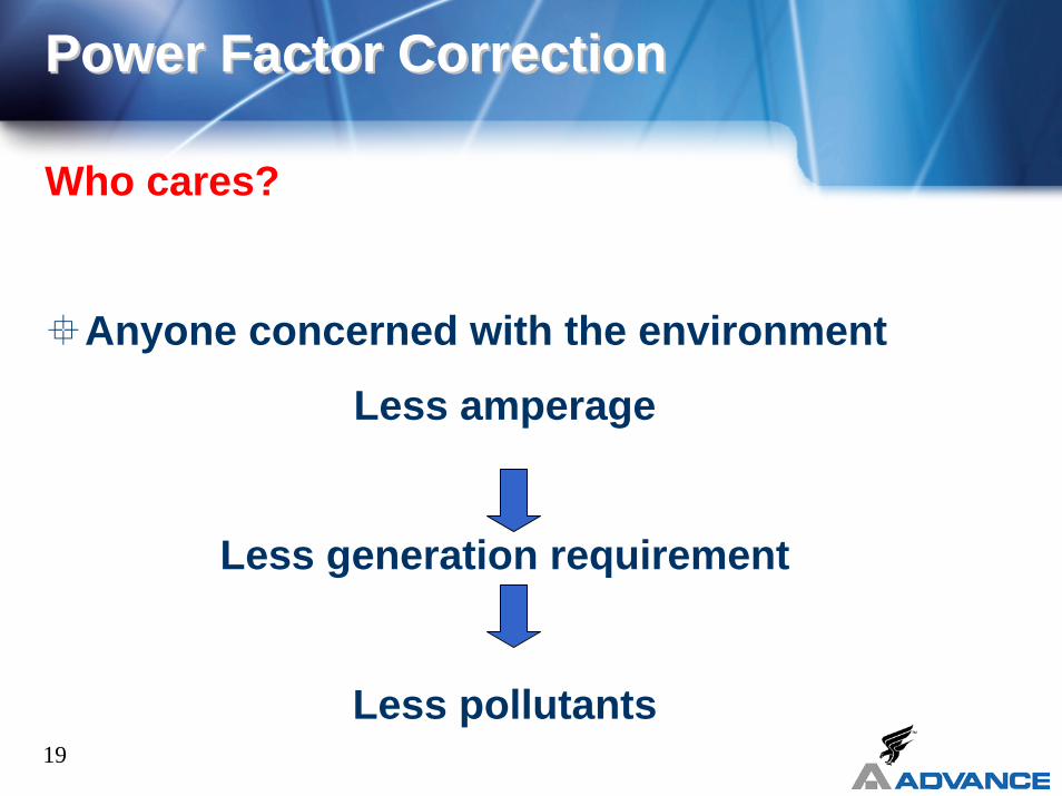
Power Factor CorrectionPower Factor Correction
Who cares?
Anyone concerned with the environment
Less amperage
Less generation requirement
Less pollutants
Page 20
20
What to look for in a DriverWhat to look for in a Driver
Performance
Regulated output
Power factor correction
Efficiency
Size
Life and Reliability
Environmental concernsTemperature rangeDry, damp, or wet location
SafetyUL Recognition/SAM listingClass 2
Page 21
Questions?Questions?
www.LEDcentral.com


![Spansion Intelligent LED Solution Introduction · Easy designing of Intelligent Lighting solution with low BOM ^ v ]}v[ LED Driver IC DC Power DALI Phy DC/DC Power Stage LED String](https://static.documents.pub/doc/80x56/5f26b195e4df1916f7007828/spansion-intelligent-led-solution-easy-designing-of-intelligent-lighting-solution.jpg)


