56
Left-handed materials: Transfer matrix method studies Peter Markos and C. M. Soukoulis
Left-handed materials: Transfer matrix method studies
Peter Markos and C. M. Soukoulis

Outline of Talk
• What are Metamaterials?
• An Example: Left-handed Materials
• Results of the transfer matrix method
• Negative n and FDTD results
• New left-handed structures
• Applications/Closing Remarks

A composite or structuredmaterial that exhibitsproperties not found innaturally occurring materialsor compounds.
Left-handed materials haveelectromagnetic properties thatare distinct from any knownmaterial, and hence areexamples of metamaterials.
What is an Electromagnetic Metamaterial?
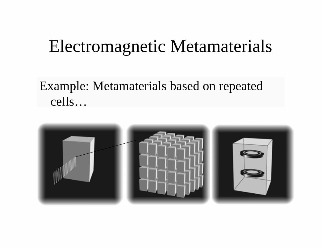
Electromagnetic Metamaterials
Example: Metamaterials based on repeatedcells…

Material Properties
All EM phenomena can be explained by Maxwell’sfour Equations.
When materials are present, we average over thedetailed properties to arrive at two parameters: m and e.
Quantities e and m are typically positive.
When e and m are both negative, there are dramatically
new properties.
Why create metamaterials?• The electromagnetic response of naturally
occurring materials is limited. Metamaterialscan extend the material properties, whilesimultaneously providing other advantageousproperties (e.g., strength, thermal, conformal)
• Possibility of materials with “ideal”electromagnetic response over broad frequencyranges, that can be customized, made active, ormade modulable or tunable.

Electromagnetic waves interactwith materials…
• Lenses
• Gratings
• Modulators
• Switches
• Antennas
• Multiplexers
• Sources

Related Terms
• Artificial Dielectrics
• Effective Medium Theory: Connects themacroscopic electromagnetic properties of acomposite to its constituent components, whetheratoms, molecules, or larger scale sub-composites.Results in e and m.
• Photonic Band Gap Periodic structures,periodicity is on the order of the wavelength.
• Metamaterials

What’s New?
• Advances in Computational Ability
• Advances in Fabrication Ability
• Market Needs

An Example: Left-handed Materials
• Predict structure and properties
• Simulate and optimize structures
• Fabricate structures
• Measure and confirm properties
• New material properties!

Veselago
We are interested in how waves propagate through variousmedia, so we consider solutions to the wave equation.
(+,+)(-,+)
(-,-) (+,-)
e,m space
k = w em
— =∂∂
=22
2EE
em emt
n
Sov. Phys. Usp. 10, 509 (1968)
Left-Handed Media: Introduction
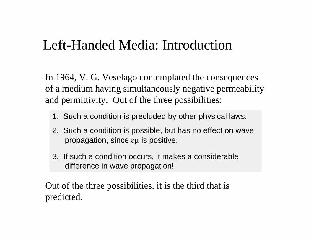
In 1964, V. G. Veselago contemplated the consequencesof a medium having simultaneously negative permeabilityand permittivity. Out of the three possibilities:
1. Such a condition is precluded by other physical laws.
2. Such a condition is possible, but has no effect on wavepropagation, since em is positive.
3. If such a condition occurs, it makes a considerabledifference in wave propagation!
Out of the three possibilities, it is the third that ispredicted.

Fundamental constraints on e and m
While we may observe a certain range of values forthe material parameters, the only fundamentallimit seems to be set by causality, which imposesthe conditions:∂( )
∂>
we
wr 1
∂( )∂
>wm
wr 1
e w e er Æ •( ) = Æ +/ 0 1
m w m mr Æ •( ) = Æ +/ 0 1
There appears to be no restriction on negative materialconstants, other than that frequency dispersion is required.
Left-Handed Media: Introduction
— ¥ = -∂∂
EBt
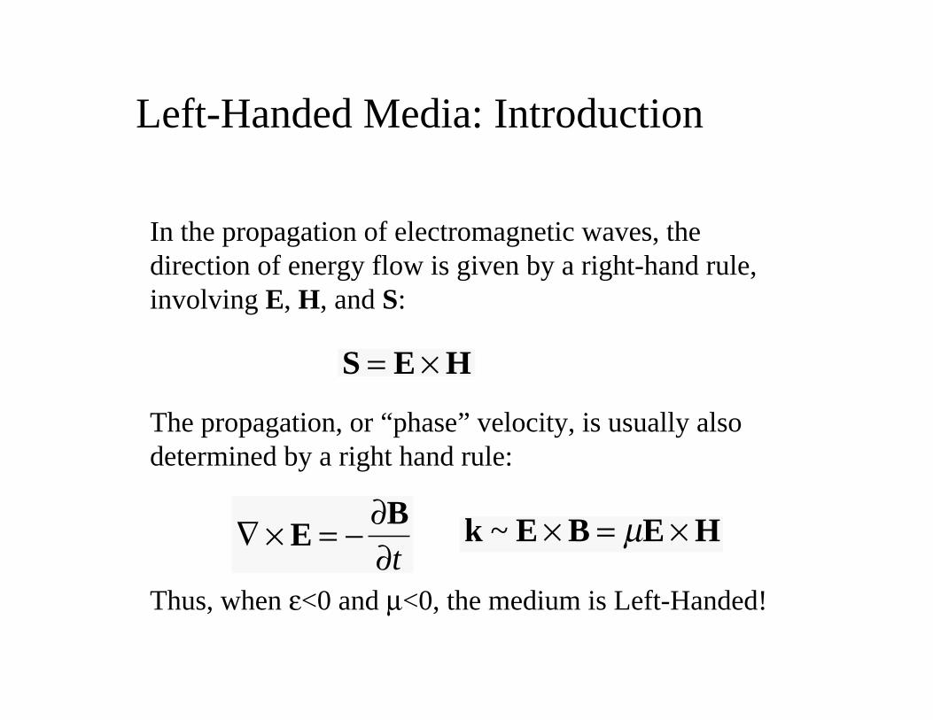
In the propagation of electromagnetic waves, thedirection of energy flow is given by a right-hand rule,involving E, H, and S:
S E H= ¥
The propagation, or “phase” velocity, is usually alsodetermined by a right hand rule:
k E B E H~ ¥ = ¥m
Thus, when e<0 and m<0, the medium is Left-Handed!

Left-Handed Media: Consequences
Group and phase velocities reversed.
A Left-Handed medium can be interpreted as having anegative refractive index, n.
sin sinq qI Tn= ±
Snell’s law still holds, but the n must be interpretedaccordingly:
Unusual and non-intuitive geometrical optics result!
n = ◊e m
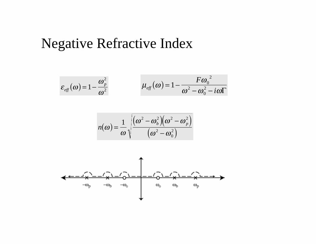
e ww
weffp( ) = -12
2m w
w
w w weff
F
i( ) = -
- -1 0
2
202 G
nb p
ww
w w w w
w w( ) =
-( ) -( )-( )
12 2 2 2
202
Negative Refractive Index

Right Handed Media Left Handed Media
kT=nkI
“Reversal” of Snell’s Law
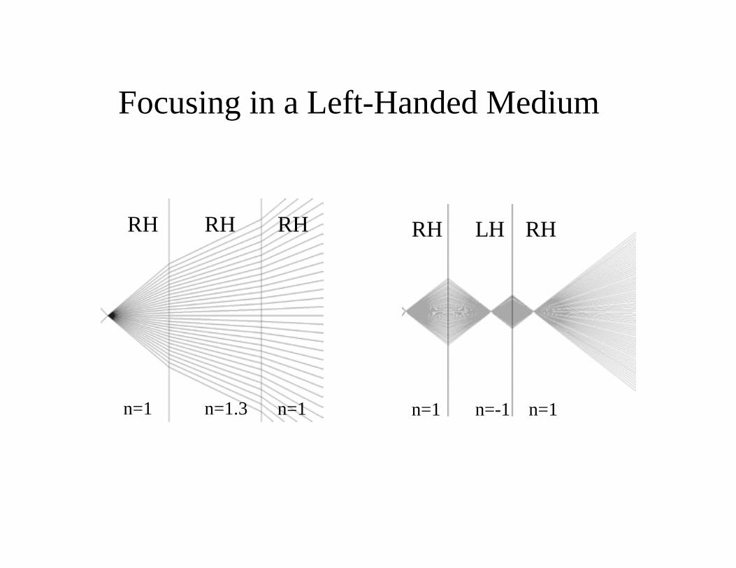
n=-1n=1 n=1
RH RHLHRH RHRH
n=1.3n=1 n=1
Focusing in a Left-Handed Medium

Metamaterials Extend Properties
e ww
w( ) = -1
2
2p
m ww
w w( ) = -
-1
2
202
p
J. B. Pendry

First Left-Handed Test Structure
UCSD, PRL 84, 4184 (2000)
Wires alone
e<0
Wires alone
Split rings alone
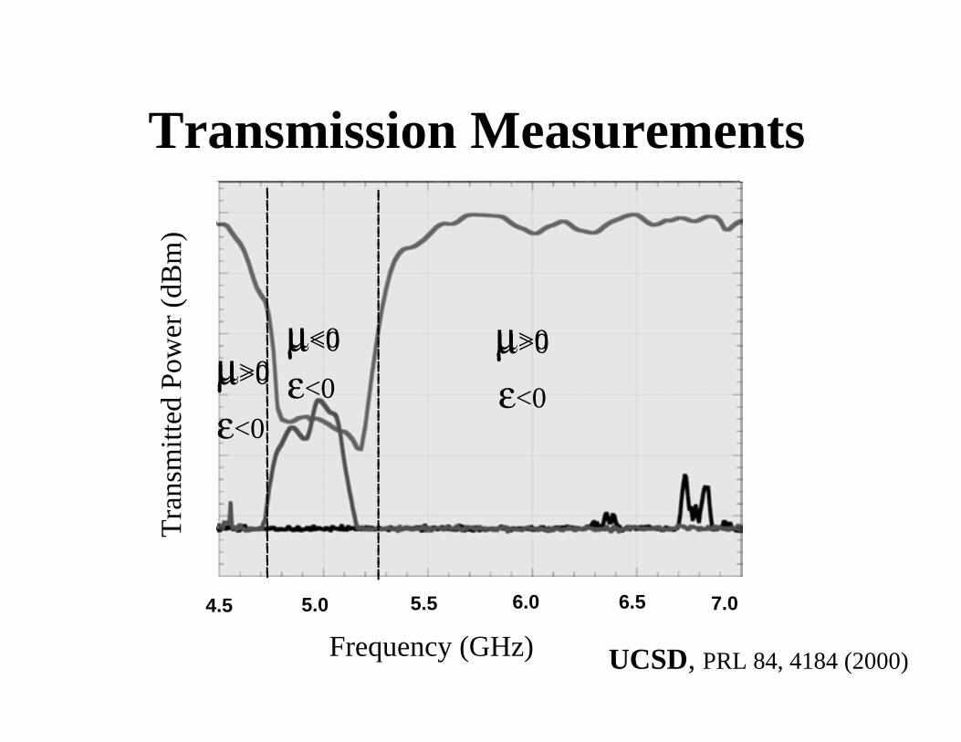
Transmission Measurements
4.5 7.05.0 5.5 6.0 6.5
Frequency (GHz)
Tra
nsm
itte
d P
ower
(dB
m)
m>0m<0m>0
m>0m<0m>0
e<0e<0
e<0
UCSD, PRL 84, 4184 (2000)

A 2-D Isotropic Structure
UCSD, APL 78, 489 (2001)

Example of Utility of Metamaterial
tikd
nkd zz
nkds =
-
( ) - +ÊË
ˆ¯
( )
exp( )
cos sin12
1
z =m
en = me
m ww
w w( ) = -
- +1
2
20
20
mp
m miG
e ww
w w( ) = -
- +1
2
20
20
ep
e eiG
The transmission coefficientis an example of a quantitythat can be determinedsimply and analytically, if thebulk material parameters areknown.
UCSD and ISU, PRB, 65, 195103 (2002)
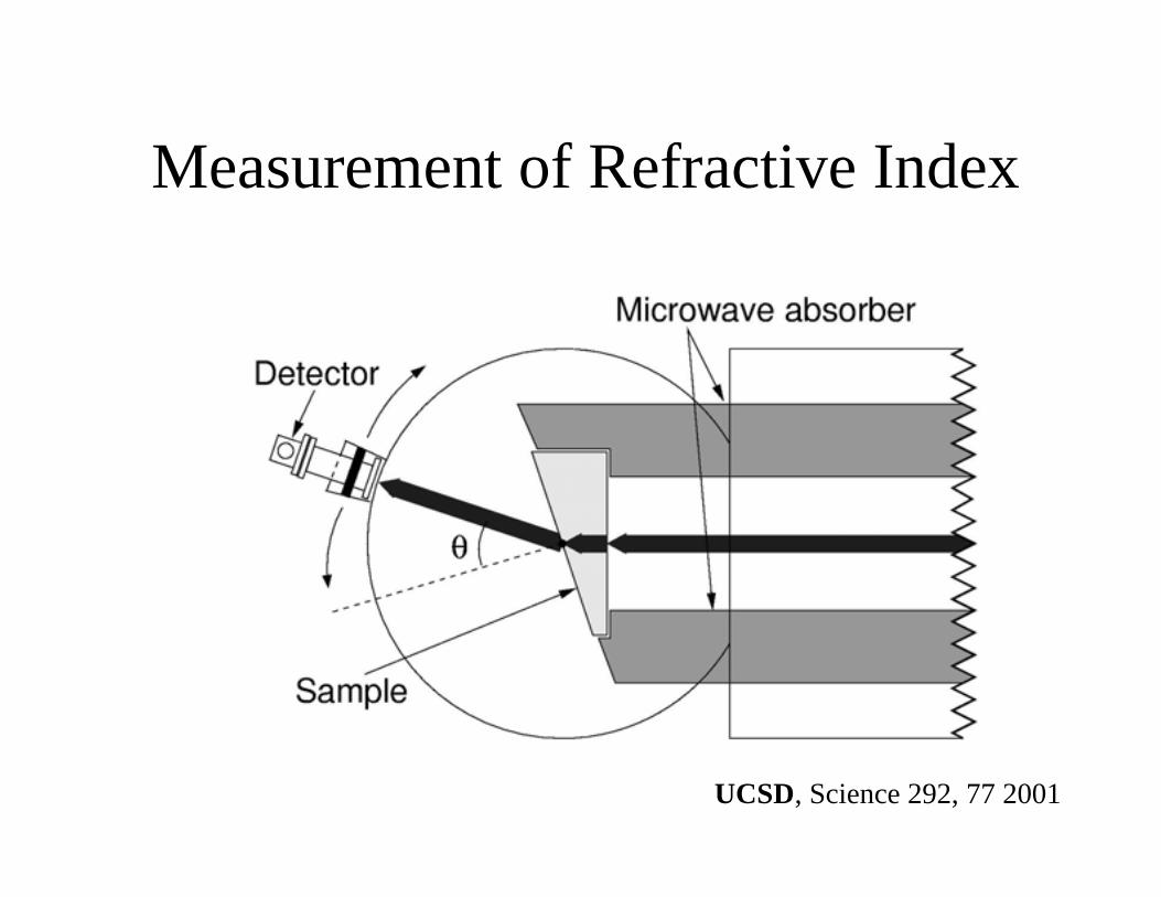
Measurement of Refractive Index
UCSD, Science 292, 77 2001

Measurement of Refractive Index
UCSD, Science 292, 77 2001

Measurement of Refractive Index
UCSD, Science 292, 77 2001

Transfer matrix is able to find:
• Transmission (p--->p, p--->s,…) p polarization
• Reflection (p--->p, p--->s,…) s polarization
• Both amplitude and phase• Absorption
Some technical details:
• Discretization: unit cell Nx x Ny x Nz : up to 24 x 24 x 24
• Length of the sample: up to 300 unit cells
• Periodic boundaries in the transverse direction
• Can treat 2d and 3d systems
• Can treat oblique angles• Weak point: Technique requires uniform discretization

Structure of the unit cell
Periodic boundary conditionsare used in transverse directions
Polarization: p wave: E parallel to y s wave: E parallel to x
For the p wave, the resonance frequencyinterval exists, where with Re meff <0, Re eeff<0and Re np <0.
For the s wave, the refraction index ns = 1.
Typical permittivity of the metallic components: emetal = (-3+5.88 i) x 105
EM wave propagates in the z -direction
Typical size of the unit cell: 3.3 x 3.67 x 3.67 mm

d c g
r
w
Structure of the unit cell:
SRR
LHM
EM waves propagatein the z-direction.Periodic boundaryconditions are usedin the xy-plane
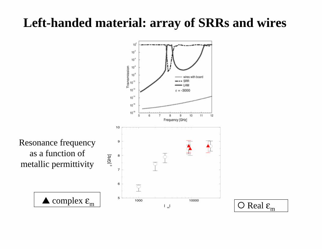
Left-handed material: array of SRRs and wires
Resonance frequencyas a function of
metallic permittivity
1000 100005
6
7
8
9
10
|�m|
� 0 [G
Hz]
complex em Real em

Dependence of LHM peak on metallic permittivity
The length of the system is 10 unit cells
6 7 8 9 10Frequency [GHz]
10−12
10−10
10−8
10−6
10−4
10−2
100
Tran
smis
sion
−588000−300000+588000 i1+588000 i1 +168000 i1 + 68000 i−38000 + 38000 i1+38000 i1+18000 i

Dependence of LHM peak on metallic permittivity

Dependence of LHM peak on L and Im eeeem
0 1 2 3 4 5 6 7 8 9 10 11Length of the system
10−8
10−7
10−6
10−5
10−4
10−3
10−2
10−1
100
101
Tra
nsm
issi
on p
eak
−588000−300000+588000 i1+588000 i1+168000 i1+68000 i1+38000 i1+18000 i1+8000 i

7.5 8 8.5 9 9.5 10 10.5Frequency [GHz]
10−12
10−10
10−8
10−6
10−4
10−2
100
Tra
nsm
issi
on
N=5N=10N=15N=20
Re(n)<0
Df=0.8GHz
# of unit cells
8 9 10 11 12 13Frequency [GHz]
10−8
10−6
10−4
10−2
100
Tran
smis
sion
N=5N=10N=15N=20
Re(n)<0
Df=1.2GHz
SRR:3x3x3 mm
# of unit cells:
Transmission depends on the orientation of SRR
Lower transmissionNarrower resonance intervalLower resonance frequency
Higher transmissionBroader resonance intervalHigher resonance frequency
Transmission properties depend on the orientation of the SRR:
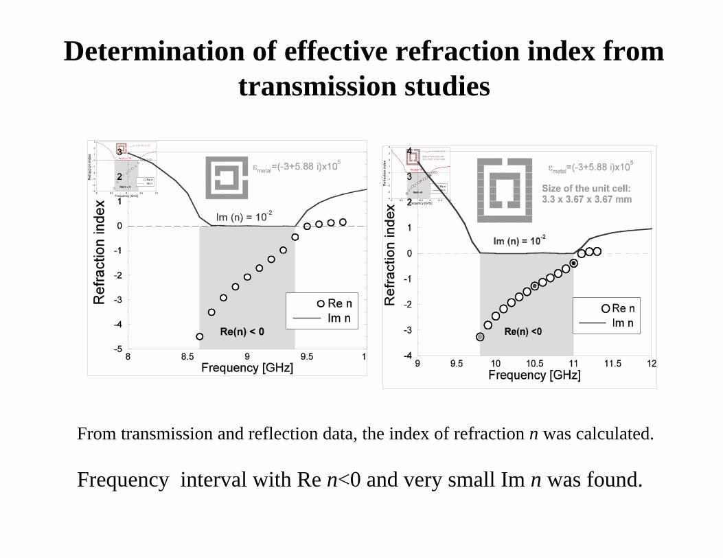
Determination of effective refraction index fromtransmission studies
8 8.5 9 9.5 10Frequency [GHz]
−5
−4
−3
−2
−1
0
1
2
3
Ref
ract
ion
inde
x
Re nIm n
Re(n) < 0
Im (n) = 10−2
emetal=(−3+5.88 i)x105
9 9.5 10 10.5 11 11.5 12Frequency [GHz]
−4
−3
−2
−1
0
1
2
3
4
Refr
act
ion in
dex
Re nIm n
Re(n) <0
Im (n) = 10−2
emetal=(−3+5.88 i)x105
Size of the unit cell:3.3 x 3.67 x 3.67 mm
From transmission and reflection data, the index of refraction n was calculated. Frequency interval with Re n<0 and very small Im n was found.

How do the Left-handed EM waves look like?
Propagation through 300unit cells was simulated.The system length is 1.1 m.
Transmission in the LHmaterial is very good.
200 225 250 275 300System length [#unit cells]
−0.2
−0.1
0.0
0.1
0.2
Rea
l par
t of t
he tr
ansm
issi
on
f=9.8 GHz n=−3.26 + 0.0155 i
0 100 200 300System length [#unit cells]
−1.0
−0.5
0.0
0.5
1.0
Rea
l par
t of t
he tr
ansm
issi
on
f=11 GHz n=−0.378 + 0.008 i
200 225 250 275 300System length [#unit cells]
−1.0
−0.5
0.0
0.5
1.0
Rea
l par
t of t
he tr
ansm
issi
on
f=10.5 GHz n=−1.31 + 0.005 i
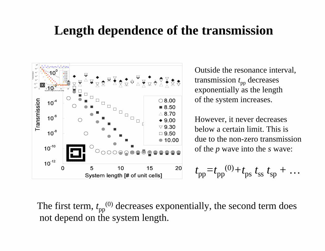
Length dependence of the transmission
tpp=tpp(0)+tps tss tsp + …
0 5 10 15 20System length [# of unit cells]
10−12
10−10
10−8
10−6
10−4
10−2
100
Tran
smis
sion 8.00
8.508.709.009.309.5010.00
Outside the resonance interval,transmission tpp decreasesexponentially as the lengthof the system increases.
However, it never decreasesbelow a certain limit. This isdue to the non-zero transmissionof the p wave into the s wave:
The first term, tpp(0) decreases exponentially, the second term does
not depend on the system length.
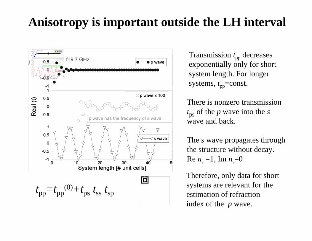
Anisotropy is important outside the LH interval
−1
−0.5
0
0.5
1
Rea
l (t)
p wave x 100
−1
−0.5
0
0.5
1
p wave
0 10 20 30 40 50System length [# unit cells]
−1
−0.5
0
0.5
1
s wave
f=9.7 GHz
p wave has the frequency of s wave!
Transmission tpp decreasesexponentially only for shortsystem length. For longersystems, tpp=const.
There is nonzero transmissiontps of the p wave into the swave and back.
The s wave propagates throughthe structure without decay.Re ns =1, Im ns=0
tpp=tpp(0)+tps tss tsp
Therefore, only data for shortsystems are relevant for theestimation of refractionindex of the p wave.

Dependence on the incident angle
8 8.5 9 9.5 10 10.5Frequency [GHz]
10−12
10−10
10−8
10−6
10−4
10−2
100
Tra
nsm
issi
on
LHM, 0LHM, 0.05LHM, 0.10SRR, 0SRR, 0.05
Incident angle [p]
9 10 11 12 13Frequency [GHz]
10−10
10−8
10−6
10−4
10−2
100
Tra
nsm
issi
on
LHM, 0LHM, 0.05LHM, 0.15
Incident angle [p]
Transmission peak does not depend on the angle of incidence !
Transition peak strongly dependson the angle of incidence.
This structure has an additionalxz - plane of symmetry
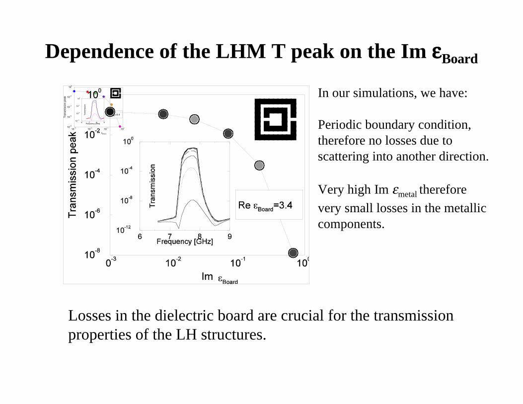
Dependence of the LHM T peak on the Im eeeeBoard
Losses in the dielectric board are crucial for the transmission properties of the LH structures.
In our simulations, we have:
Periodic boundary condition,therefore no losses due toscattering into another direction.
Very high Im emetal therefore
very small losses in the metalliccomponents.
10−3
10−2
10−1
100
Im
10−8
10−6
10−4
10−2
100
Tra
nsm
issi
on p
eak
6 7 8 9Frequency [GHz]
10−12
10−8
10−4
100
Tra
nsm
issi
on
eBoard
Re eBoard=3.4

Another 1D left-handed structure:
6 7 8 9 10Frequency [GHz]
10−14
10−12
10−10
10−8
10−6
10−4
10−2
100
Tran
smis
sion
SRRLHM
Unit cell:
5x3.3x5 mm
8 8.5 9 9.5 10Frequency [GHz]
10−10
10−8
10−6
10−4
10−2
100
Tran
smis
sion
SRRLHM
emetal=(−3+5.88)x105
Both SRR and wires are located on the same side of the dielectric board.Transmission depends on the orientation of SRR.

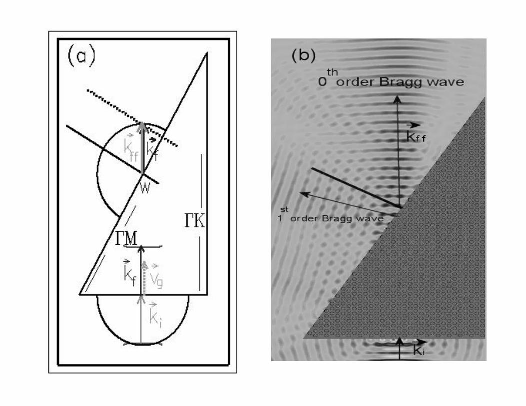
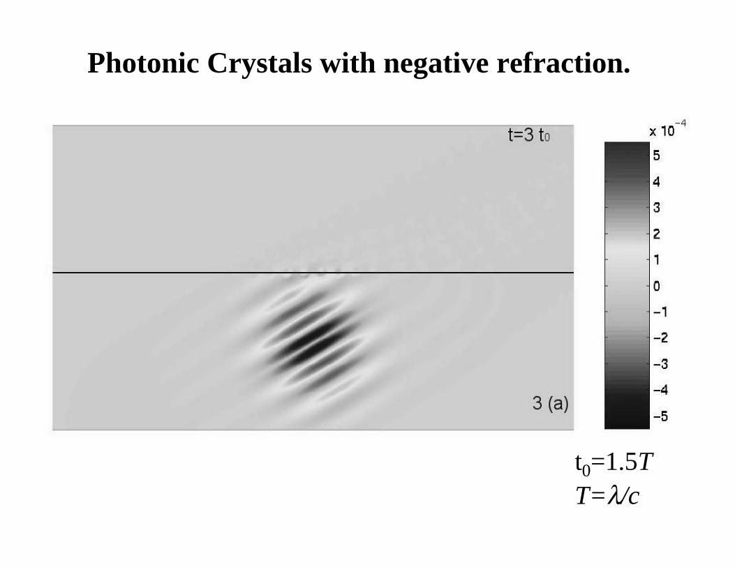
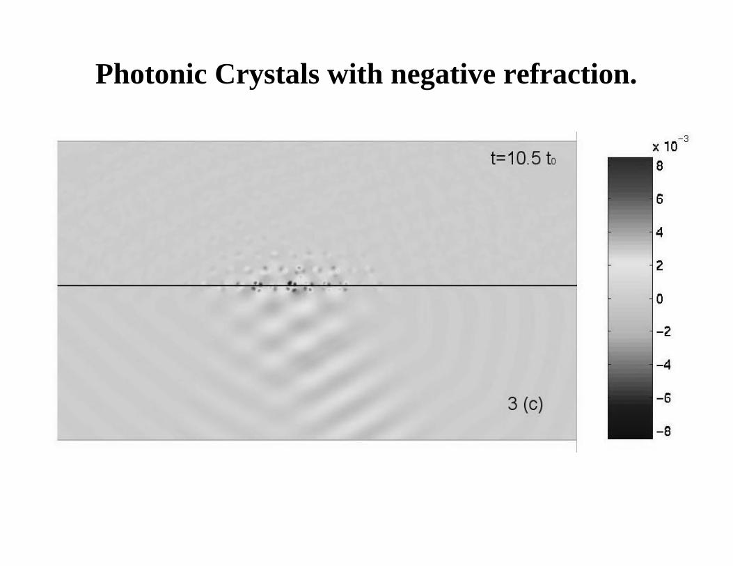
Photonic Crystals with negative refraction.

Photonic Crystals with negative refraction.
FDTD simulations were used to study the time evolution of an EMwave as it hits the interface vacuum/photonic crystal.Photonic crystal consists of an hexagonal lattice of dielectric rodswith e=12.96. The radius of rods is r=0.35a. a is the lattice constant.
PhotonicCrystal
vacuum
Photonic Crystals with negative refraction.
t0=1.5TT=l/c

Photonic Crystals with negative refraction.
Photonic Crystals with negative refraction.

Photonic Crystals with negative refraction.

Photonic Crystals: negative refraction
The EM wave is trapped temporarily at the interface and after a long time,the wave front moves eventually in the negative direction. Negative refraction was observed for wavelength of the EM wavel= 1.64 – 1.75 a (a is the lattice constant of PC)

Conclusions
• Simulated various structures of SRRs & LHMs• Predicted how resonance transmission frequency depends on the parameters of the system• Calculated transmission, reflection and absorption
• Calculated meff and eeff and refraction index (with UCSD)
• Analyzed transmission properties of 2d and 3d structures• Found negative refraction in photonic crystals
Publications: P. Markos and C. M. Soukoulis, Phys. Rev. B 65, 033401 (2002) P. Markos and C. M. Soukoulis, Phys. Rev. E 65, 036622 (2002) D. R. Smith, S. Schultz, P. Markos and C.M.Soukoulis, Phys. Rev. B 65, 195104 (2002) M. Bayindir, K. Aydin, E. Ozbay, P. Markos and C. M. Soukoulis, Appl. Phys. Lett. (2002) P. Markos, I. Rousochatzakis and C. M. Soukoulis, submitted (2002) S. Foteinopoulou, E. N. Economou and C. M. Soukoulis, submitted (2002)
DOE, DARPA, NSF
Metamaterials: New MaterialResponses for Applications
Compact cell phone antennas
Improvements to base station antenna
Multiple degree-of-freedom antennas for MIMO
Active materials for beam steering/smart antennas (SDMA)
Phased array antennas
Military applications