22
• Left side compressor behind Left control box • Right side compressor behind Right control box
| Date post: | 26-Dec-2015 |
| Category: |
Documents |
| Upload: | delilah-paul |
| View: | 227 times |
| Download: | 3 times |
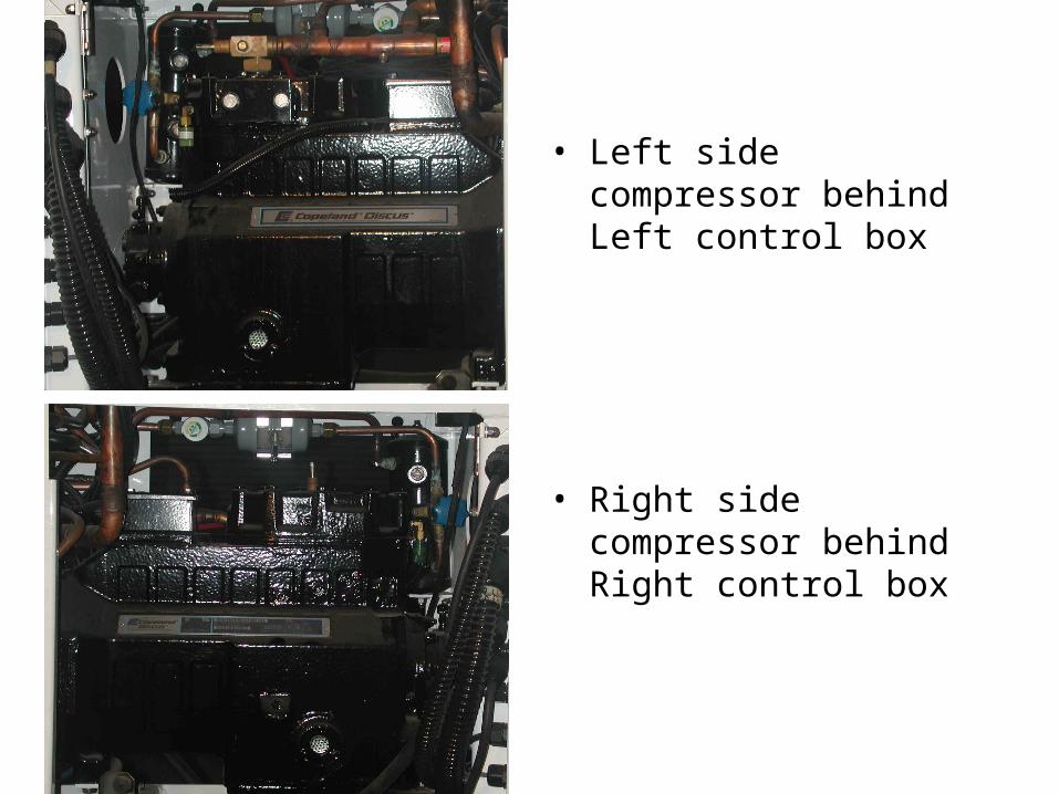
• Left side compressor behind Left control box
• Right side compressor behind Right control box
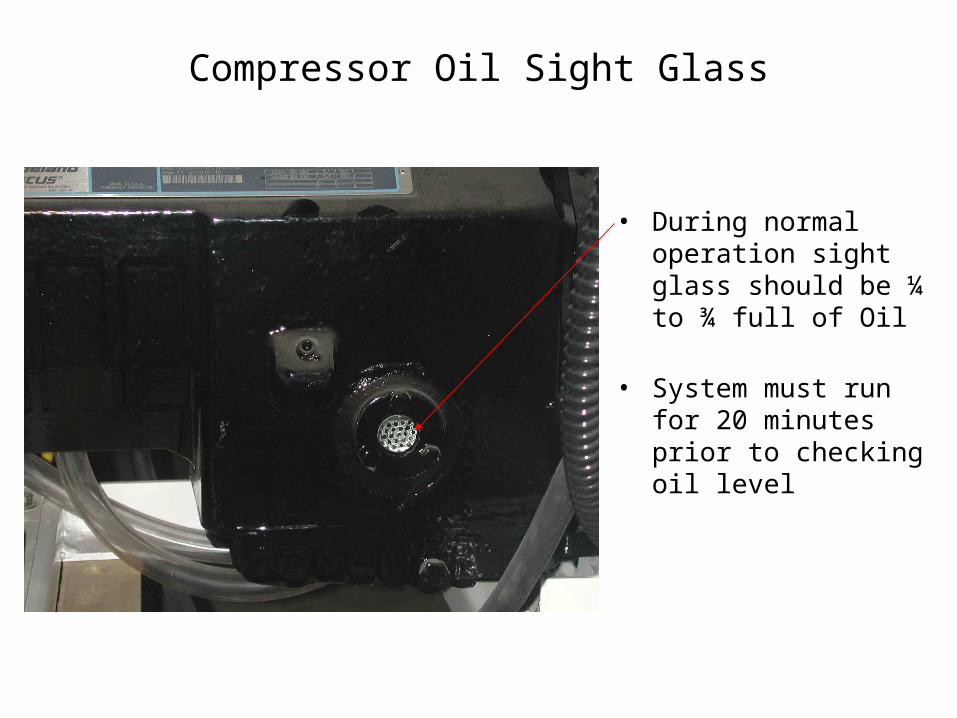
Compressor Oil Sight Glass
• During normal operation sight glass should be ¼ to ¾ full of Oil
• System must run for 20 minutes prior to checking oil level
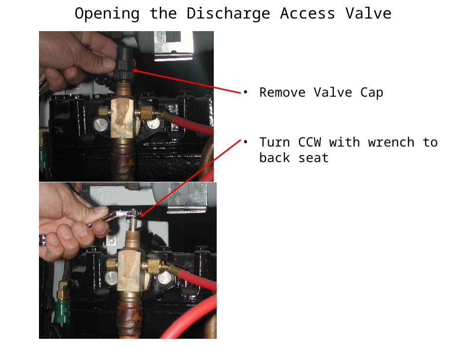
Opening the Discharge Access Valve
• Remove Valve Cap
• Turn CCW with wrench to back seat
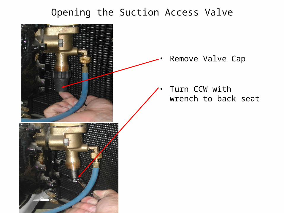
Opening the Suction Access Valve
• Remove Valve Cap
• Turn CCW with wrench to back seat
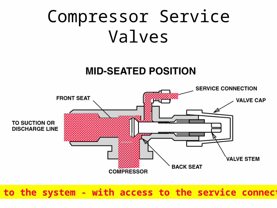
Compressor Service Valves
Open to the system - with access to the service connection!
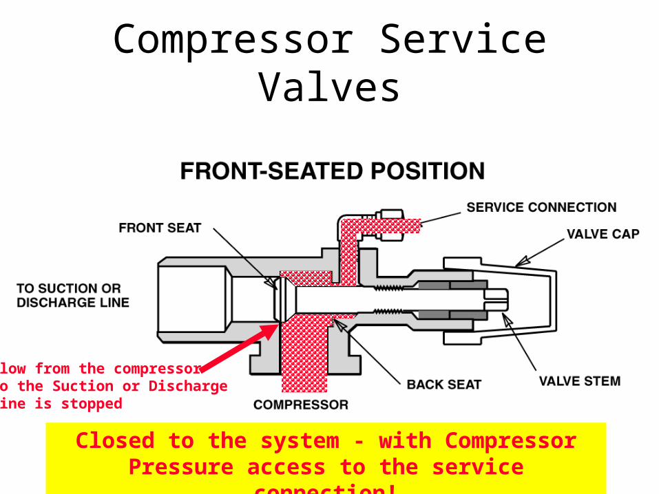
Compressor Service Valves
Flow from the compressorto the Suction or Dischargeline is stopped
Closed to the system - with Compressor Pressure access to the service connection!
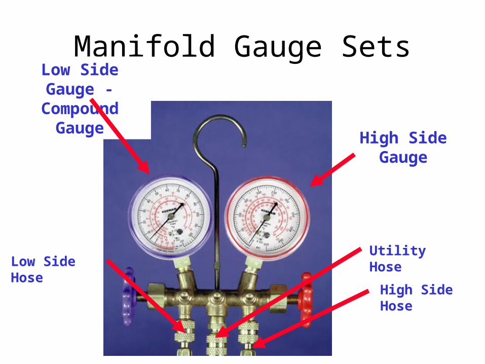
Manifold Gauge Sets
High Side Gauge
Low Side Gauge - Compound Gauge
Utility Hose
High Side Hose
Low Side Hose
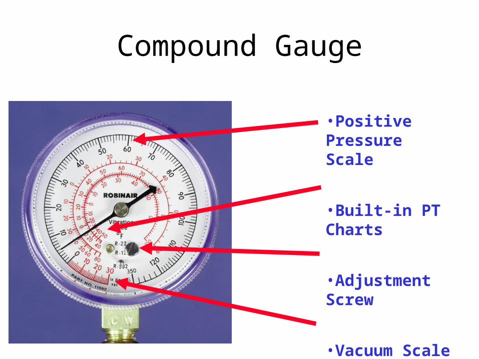
Compound Gauge
•Positive Pressure Scale
•Built-in PT Charts
•Adjustment Screw
•Vacuum Scale (Reference Only!)
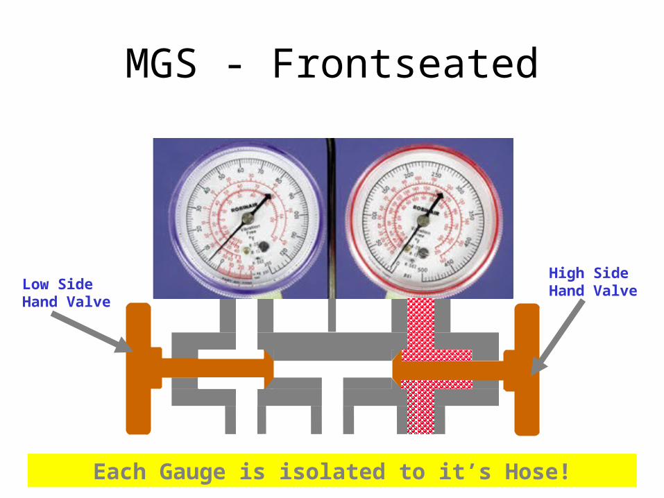
MGS - Frontseated
Each Gauge is isolated to it’s Hose!
High Side Hand ValveLow Side
Hand Valve
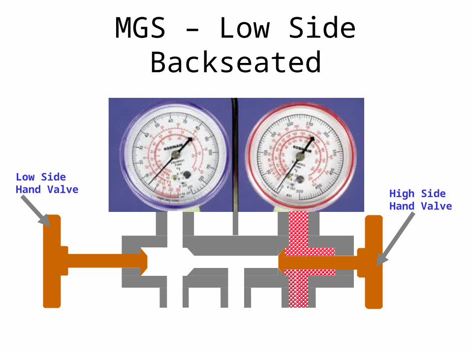
MGS – Low Side Backseated
High Side Hand Valve
Low Side Hand Valve
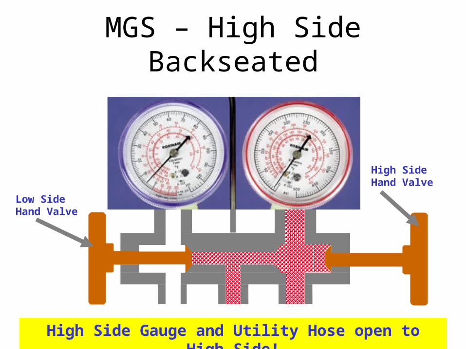
MGS – High Side Backseated
High Side Gauge and Utility Hose open to High Side!
High Side Hand Valve
Low Side Hand Valve
Installation, Purging & Removal of Manifold Gauge
Sets (MGS)
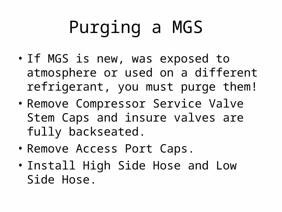
Purging a MGS
• If MGS is new, was exposed to atmosphere or used on a different refrigerant, you must purge them!
• Remove Compressor Service Valve Stem Caps and insure valves are fully backseated.
• Remove Access Port Caps.• Install High Side Hose and Low Side Hose.
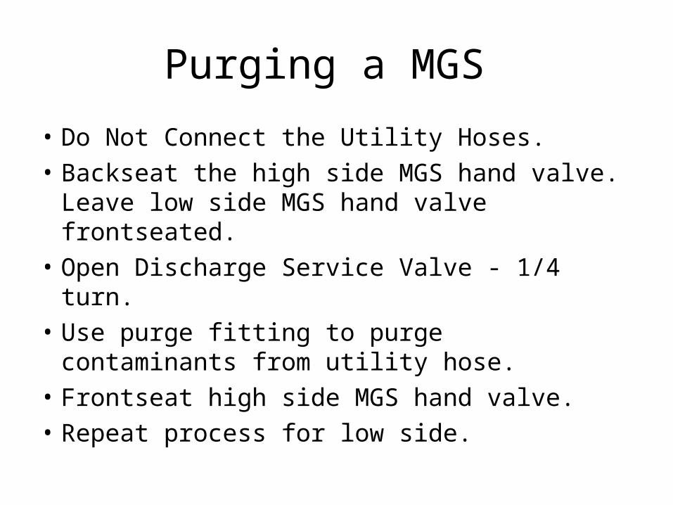
Purging a MGS
• Do Not Connect the Utility Hoses.
• Backseat the high side MGS hand valve. Leave low side MGS hand valve frontseated.
• Open Discharge Service Valve - 1/4 turn.
• Use purge fitting to purge contaminants from utility hose.
• Frontseat high side MGS hand valve.
• Repeat process for low side.
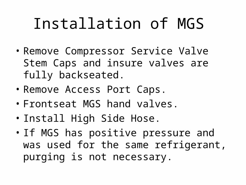
Installation of MGS
• Remove Compressor Service Valve Stem Caps and insure valves are fully backseated.
• Remove Access Port Caps.• Frontseat MGS hand valves.• Install High Side Hose.• If MGS has positive pressure and was used
for the same refrigerant, purging is not necessary.
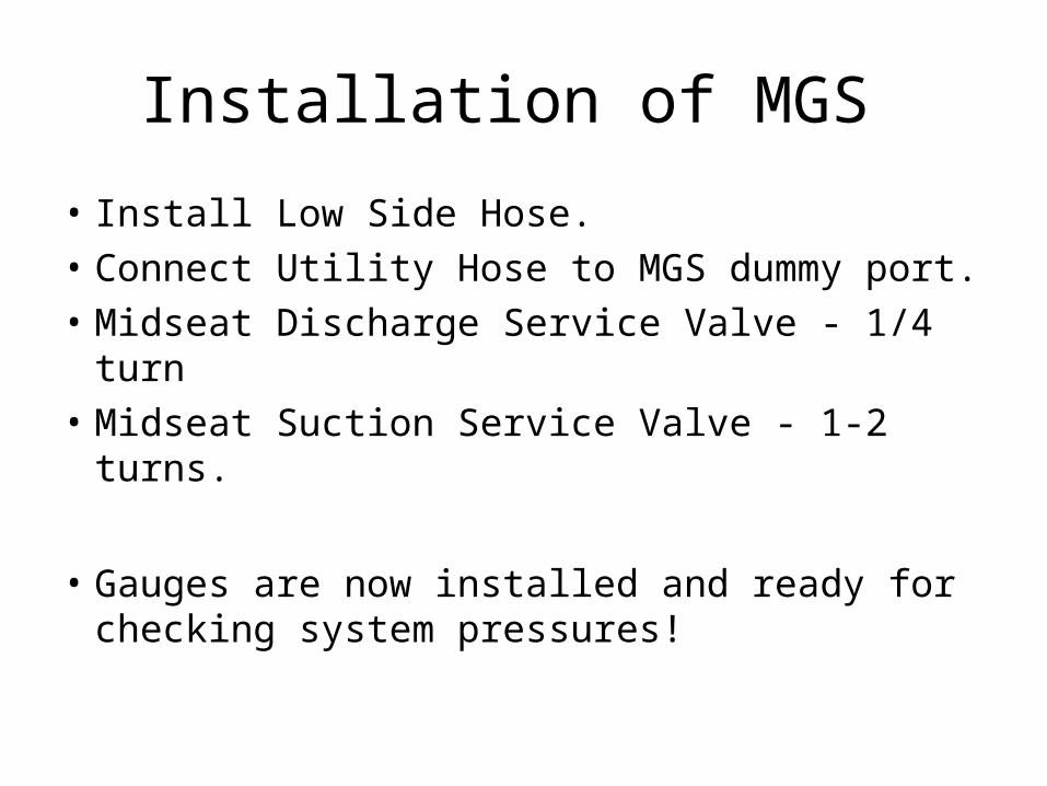
Installation of MGS
• Install Low Side Hose.
• Connect Utility Hose to MGS dummy port.
• Midseat Discharge Service Valve - 1/4 turn
• Midseat Suction Service Valve - 1-2 turns.
• Gauges are now installed and ready for checking system pressures!
Removal of MGS
• With the unit operating.– Backseat the Discharge Service Valve.– Midseat the MGS Hand Valves.– Let the pressure in the MGS stabilize to
Suction Pressure.– Frontseat the MGS Hand Valves.– Backseat the Suction Service Valve.– Remove Hoses.
Low Side Pump-down
• Purpose– To perform general service on the Filter-drier,
Modulation Valve, Suction Solenoid Valve, Heat Exchanger and TXV Valve.
• Procedure– Install Manifold Gauge Set.– Operate unit in Cool Mode for 15 - 20
minutes.– Close the Liquid Line Hand Valve.
Low Side Pump-down
• Procedure (con’t)– Monitor the Low Side Gauge and shut unit OFF
when it reaches a slight vacuum (5” hg max.)– Monitor the Low side gauge:
• Pressure rises above 2-3 PSIG - pump down again!• Pressure does not rise above 2-3 PSIG - continue!
– Front-seat the Suction Service Valve.
• All Refrigerant is now trapped in the Condenser and the Receiver tank!
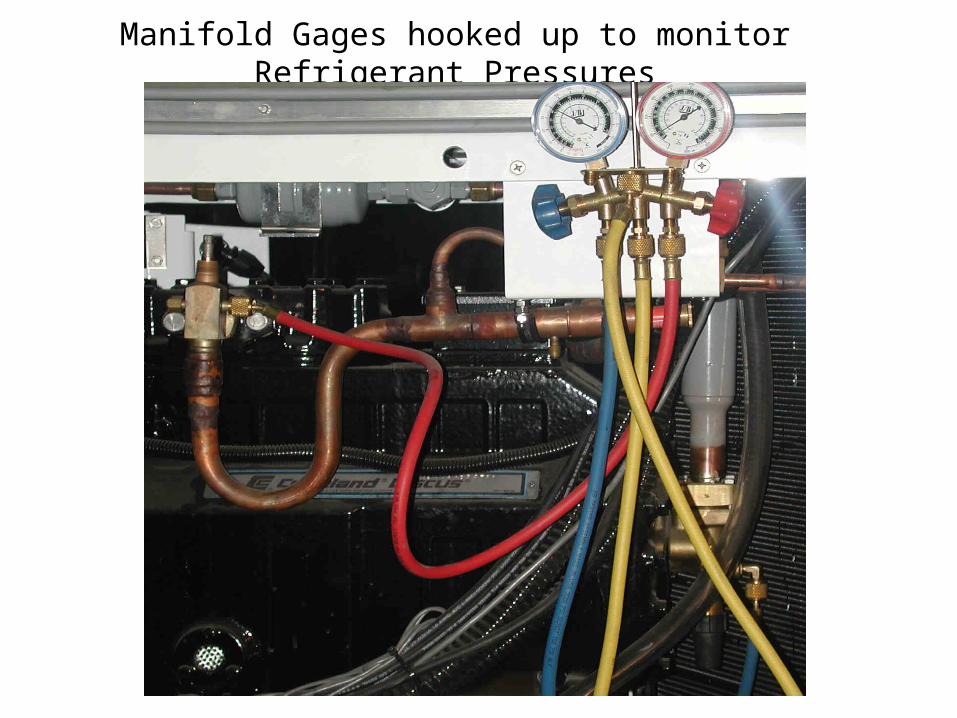
Manifold Gages hooked up to monitor Refrigerant Pressures
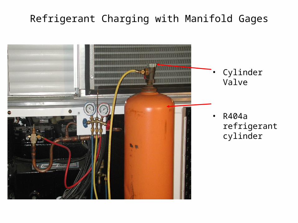
Refrigerant Charging with Manifold Gages
• Cylinder Valve
• R404a refrigerant cylinder
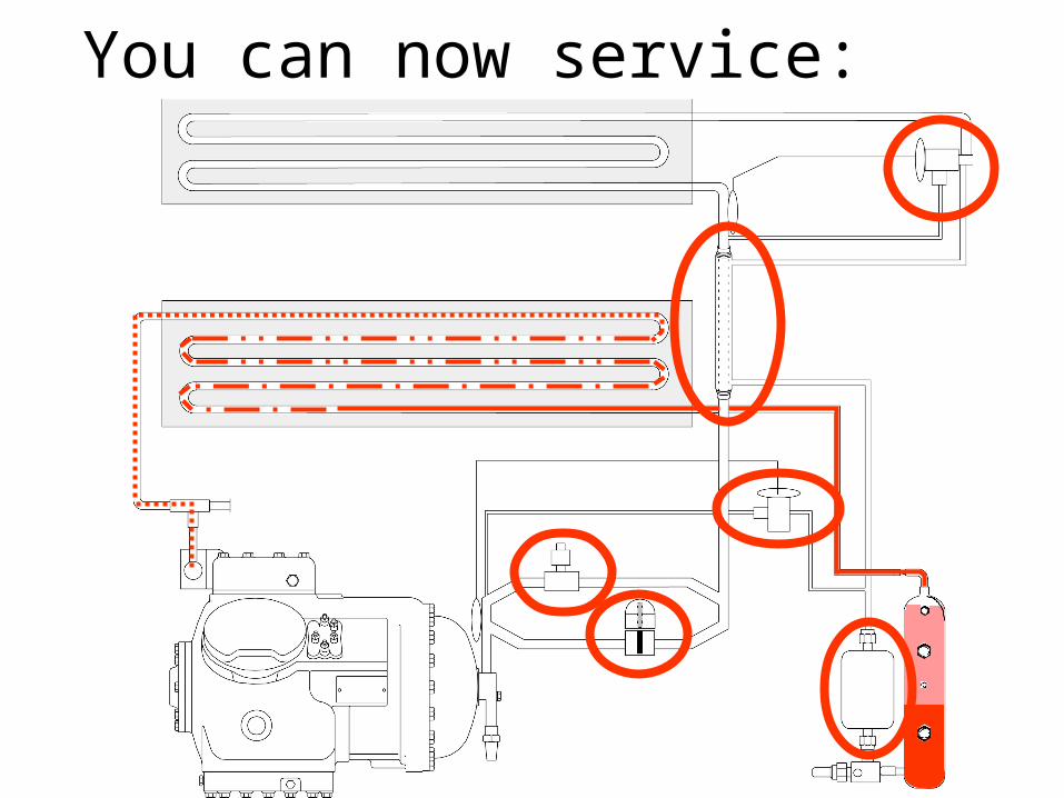
You can now service:


