+ All Categories
Home > Documents > leg04_trans_02-1

leg04_trans_02-1

Date post: 03-Jun-2018
Category:
Upload: maximiliano-andres-cortes-gonzalez
View: 222 times
Download: 0 times
Share this document with a friend
48
FUJI HEA VY INDUSTRIES L TD. G2320GE5 2004 LEGACY SERVICE MANUAL QUICK REFERENCE INDEX TRANSMISSION SECTION This service manual has been prepared to provide SUBARU service personnel with the necessary information and data for the correct maintenance and repair of SUBARU vehicles. This manual includes the procedures for maintenance, disassembling, reas- sembling, inspection and adjustment of components and diagnostics for guid- ance of experienced mechanics. Please peruse and utilize this manual fully to ensure complete repair work for satisfying our customers by keeping their vehicle in optimum condition. When replacement of parts during repair work is needed, be sure to use SUBARU genuine parts. All information, illustration and specifi- cations contained in this manual are based on the latest product information available at the time of publication approval. CONTROL SYSTEMS CS AUTOMATIC T RANSMISSION 4A T AUTOMATIC TRANSMISSION (DIAGNOSTICS) 4AT(diag) AUTOMATIC TRANSMISSION 5AT AUTOMATIC TRANSMISSION (DIAGNOSTICS) 5AT(diag) MANUAL TRANSMISSION AND DIFFERENTIAL 5MT CLUTCH SYSTEM CL
Transcript

8/12/2019 leg04_trans_02-1

http://slidepdf.com/reader/full/leg04trans02-1 1/48

FUJI HEAVY INDUSTRIES LTD. G2320GE5

2004 LEGACY SERVICE MANUAL QUICK REFERENCE INDEX

TRANSMISSION SECTION

This service manual has been prepared

to provide SUBARU service personnelwith the necessary information and data

for the correct maintenance and repairof SUBARU vehicles.

This manual includes the proceduresfor maintenance, disassembling, reas-sembling, inspection and adjustment of

components and diagnostics for guid-ance of experienced mechanics.

Please peruse and utilize this manualfully to ensure complete repair work forsatisfying our customers by keeping

their vehicle in optimum condition.When replacement of parts during

repair work is needed, be sure to useSUBARU genuine parts.

All information, illustration and specifi-cations contained in this manual are

based on the latest product informationavailable at the time of publication

approval.

CONTROL SYSTEMS CS

AUTOMATIC TRANSMISSION 4AT

AUTOMATIC TRANSMISSION(DIAGNOSTICS)

4AT(diag)

AUTOMATIC TRANSMISSION 5AT

AUTOMATIC TRANSMISSION

(DIAGNOSTICS)5AT(diag)

MANUAL TRANSMISSION AND

DIFFERENTIAL5MT

CLUTCH SYSTEM CL

8/12/2019 leg04_trans_02-1

http://slidepdf.com/reader/full/leg04trans02-1 2/48

8/12/2019 leg04_trans_02-1

http://slidepdf.com/reader/full/leg04trans02-1 3/484AT-2

AUTOMATIC TRANSMISSIONGeneral Description

1. General Description

A: SPECIFICATION

1. TORQUE CONVERTER CLUTCH

2. OIL PUMP

3. TRANSMISSION CONTROL ELEMENT

4. TRANSMISSION GEAR RATIO

5. PLANETARY GEAR AND PLATE

6. SELECTOR POSITION

Model 2.0 L 2.5 L

Type

Symmetric, 3 element, single stage,

2 phase torque converter

Stall torque ratio 2.0 — 2.2 2.1 — 2.3

Nomi-

nal

diame-

ter

mm (in) 236 (9.29) 249 (9.69)

Stall speed (at sea

level)

2,300 — 2,700

rpm

2,500 — 2,900

rpm

One-way clutch Sprague type one-way clutch

Type Pracoid constant-displacement pump

Driving method Driven by engine

Number of teethInner rotor 9

Outer rotor 10

Type4-forward, 1-reverse,

double-row planetary gears

Multi-plate clutch 3 sets

Multi-plate brake 2 sets

One-way clutch

(sprague type)1 sets

1st 2.785

2nd 1.545

3rd 1.000

4th 0.694

Rev 2.272

Model 2.0 L 2.5 L

Front sun gear

number of teeth33

Front pinion num-

ber of teeth21

Front internal gearnumber of teeth 75

Rear sun gear

number of teeth42

Rear pinion num-

ber of teeth17

Rear internal gear

number of teeth75

Drive plate num-

ber of high clutch4

Drive plate num-

ber of low clutch4 5

Drive plate num-

ber of reverseclutch

2

Drive plate num-

ber of 2-4 brake2 3

Drive plate num-

ber of low &

reverse brake

4 5

P (Park)

Transmission in neutral, output mem-

ber immovable, and engine start possi-

ble

R (Reverse) Transmission in reverse for backing

N (Neutral)Transmission in neutral and engine

start possible

D (Drive)4-forward automatic gear change

1st ←→ 2nd ←→ 3rd ←

→ 4th

SPORT mode4-forward automatic gear change

1st ←→ 2nd ←→ 3rd ←

→ 4th

Manual mode (+)

4-forward manual gear change

(shift up)

1st → 2nd → 3rd → 4th

Manual mode (−)

4-forward manual gear change

(shift down)

1st←

2nd←

 3rd←

 4thControl method Wire cable

8/12/2019 leg04_trans_02-1

http://slidepdf.com/reader/full/leg04trans02-1 4/48

8/12/2019 leg04_trans_02-1

http://slidepdf.com/reader/full/leg04trans02-1 5/484AT-4

AUTOMATIC TRANSMISSIONGeneral Description

B: COMPONENT

1. TORQUE CONVERTER CLUTCH AND CASE

(1) Pitching stopper bracket (10) O-ring (18) Bracket (if equipped)

(2) O-ring (11) Torque converter clutch ASSY (19) Clip (if equipped)

(3) Differential oil level gauge (12) Drain plug

(4) Stay (13) Gasket Tightening torque: N ⋅ m  (kgf-m, ft-lb)

(5) Seal pipe (14) Oil seal T1: 18 (1.8, 13.0)

(6) Oil pump shaft (15) Converter case T2: 23 (2.3, 16.7)

(7) Clip (16) Harness stay T3: 33 (3.4, 24.3)

(8) Oil drain pipe (17) ATF cooler ASSY with warmer

function (if equipped)

T4: 41 (4.2, 30.4)

(9) Input shaft T5: 70 (7.1, 51.6)

AT-02159

T4

T4

T4

T4

T5

T1

(8)

(11)

(1)(2)

(16)

(18)

(17)

(19) (3)

(4)

(7)

(5)

(6)

(10)

(9)

(14)

(15)

(12)

(13)

T3

T2

8/12/2019 leg04_trans_02-1

http://slidepdf.com/reader/full/leg04trans02-1 6/484AT-5

AUTOMATIC TRANSMISSIONGeneral Description

2. OIL PUMP

(1) Oil pump rotor (11) Gasket (21) Lock nut

(2) Oil pump cover (12) O-ring

(3) Seal ring (13) Test plug Tightening torque: N ⋅ m  (kgf-m, ft-lb)

(4) Thrust needle bearing (14) Stud bolt T1: 7 (0.7, 5.1)

(5) Drive pinion shaft (15) O-ring T2: 13 (1.3, 9.4)

(6) Roller bearing (16) O-ring T3: 18 (1.8, 13.0)

(7) Shim (17) Oil seal retainer T4: 25 (2.5, 18.1)

(8) Oil pump housing (18) Oil seal T5: 40 (4.1, 30)

(9) Nipple (19) O-ring T6: 42 (4.3, 31)

(10) Air breather hose (20) Drive pinion collar T7: 116 (11.8, 85)

AT-00003

8/12/2019 leg04_trans_02-1

http://slidepdf.com/reader/full/leg04trans02-1 7/484AT-6

AUTOMATIC TRANSMISSIONGeneral Description

3. TRANSMISSION CASE AND CONTROL DEVICE

AT-02160

(1)

(2)

(3)

(4)

(10)

(12)

(13)

(14)

(15)

(16)

(17)(18)(20)

(19)

(21)(25)

(30)

(36)

(11)

(12)

(5)

(6)

(7)

(8)

(9)(40)

(26)

(23)

(24)

(22)(11)

(28)(28)

(29)

(29)

(32)

(33)

(31)

(35)(38)

(37)

(34)

(39)

T1

T5

T6

T9

T2

T9

T9

T9

T9

T9

T3  T7

T9T4

T10

T3

(28)   (27)

(41)

(31)T9

T8

8/12/2019 leg04_trans_02-1

http://slidepdf.com/reader/full/leg04trans02-1 8/48

8/12/2019 leg04_trans_02-1

http://slidepdf.com/reader/full/leg04trans02-1 9/48

8/12/2019 leg04_trans_02-1

http://slidepdf.com/reader/full/leg04trans02-1 10/484AT-9

AUTOMATIC TRANSMISSIONGeneral Description

5. HIGH CLUTCH AND REVERSE CLUTCH

(1) High clutch drum (8) Spring retainer (15) Dish plate

(2) Lip seal (9) Cover (16) Driven plate (reverse clutch)

(3) D-ring (10) Snap ring (17) Drive plate (reverse clutch)

(4) Reverse clutch piston (11) Driven plate (high clutch) (18) Retaining plate (reverse clutch)

(5) D-ring (12) Drive plate (high clutch) (19) Snap ring

(6) D-ring (13) Retaining plate (high clutch) (20) Thrust needle bearing

(7) High clutch piston (14) Snap ring (21) High clutch hub

AT-00006

8/12/2019 leg04_trans_02-1

http://slidepdf.com/reader/full/leg04trans02-1 11/484AT-10

AUTOMATIC TRANSMISSIONGeneral Description

6. PLANETARY GEAR AND 2-4 BRAKE

(1) Thrust needle bearing (10) Washer (19) Snap ring

(2) Front sun gear (11) Thrust needle bearing (20) Spring retainer

(3) Thrust needle bearing (12) Rear internal gear (21) 2-4 brake piston

(4) Snap ring (13) Washer (22) D-ring

(5) Front planetary carrier (14) Snap ring (23) D-ring

(6) Thrust needle bearing (15) Retaining plate (24) 2-4 brake piston retainer

(7) Rear sun gear (16) Drive plate (25) 2-4 brake seal

(8) Thrust needle bearing (17) Driven plate (26) Leaf spring

(9) Rear planetary carrier (18) Pressure rear plate

AT-00007

(1)

(2)

(3)

(4)

(5)

(6)

(14)

(15)

(16)

(16)

(16)

(18)

(17)

(20)

(26)

(17)

(7)

(8)

(9)

(10)

(11)

(12)(13)

(19)

(21)

(22)

(23)(25)

(24)

8/12/2019 leg04_trans_02-1

http://slidepdf.com/reader/full/leg04trans02-1 12/484AT-11

AUTOMATIC TRANSMISSIONGeneral Description

7. LOW CLUTCH AND LOW & REVERSE BRAKE

(1) Snap ring (12) Low clutch dram (23) Return spring

(2) Retaining plate (13) Needle bearing (24) Snap ring

(3) Drive plate (14) Snap ring (25) Retaining plate

(4) Driven plate (15) One-way clutch (26) Leaf spring

(5) Dish plate (16) Snap ring (27) Drive plate

(6) Snap ring (17) Thrust needle bearing (28) Driven plate

(7) Cover (18) Seal ring (29) Dish plate

(8) Spring retainer (19) Needle bearing (30) Low & reverse brake piston

(9) D-ring (20) One-way clutch inner race

(10) Low clutch piston (21) Socket bolt Tightening torque: N ⋅ m  (kgf-m, ft-lb)

(11) D-ring (22) Spring retainer T: 25 (2.5, 18.1)

AT-01278

(2)

(3)(4)

(3)

(4)

(5)   (6)

(7)(8)

(9)

(10)   (11)

(12)

(17)

(24)  (26)(25)

(27)

(28)

(27)

(28)

(29)

(30)(18)

(19)(20)

(23)

(21)

(22)

(13)(14)

(15)

(16)

T

(1)

8/12/2019 leg04_trans_02-1

http://slidepdf.com/reader/full/leg04trans02-1 13/484AT-12

AUTOMATIC TRANSMISSIONGeneral Description

8. REDUCTION GEAR

(1) Seal ring (6) Snap ring (11) Lock nut

(2) Ball bearing (7) Ball bearing

(3) Reduction drive gear (8) Snap ring Tightening torque: N ⋅ m  (kgf-m, ft-lb)

(4) Reduction drive shaft (9) Reduction driven gear T: 100 (10.2, 73.8)

(5) Drive pinion shaft (10) Washer

AT-02161

(10)

(1)

(2)

(3)

(4)

(11)   T

(5)

(6)

(7)

(8)

(8)

(8)

(9)

8/12/2019 leg04_trans_02-1

http://slidepdf.com/reader/full/leg04trans02-1 14/484AT-13

AUTOMATIC TRANSMISSIONGeneral Description

9. REDUCTION GEAR WITH VTD

(1) Ball bearing (13) Rear drive shaft (25) Snap ring

(2) Reduction drive gear (14) Ball bearing (26) Ball bearing

(3) Washer (15) Multi-plate clutch (LSD) hub (27) Snap ring

(4) Needle bearing (16) Ball bearing (28) Reduction driven gear

(5) Pinion gear (17) Revolution gear (29) Lock washer

(6) Carrier (18) Driven plate (Thicker) (30) Lock nut

(7) Planetary pinion shaft (19) Drive plate (31) Gasket

(8) Snap ring (20) Driven plate (Thinner) (32) Extension case

(9) Seal ring (21) Driven plate (Thicker)

(10) Thrust needle bearing (22) Pressure plate Tightening torque: N ⋅ m (kgf-m, ft-lb) 

(11) Intermediate shaft (23) Rear drive shaft shim T: 100 (10.2, 73.8) 

(12) Thrust washer (24) Drive pinion shaft

AT-02203

T

(3)(4)

(5)(4)

(3) (2)

(1)

(6)

(7)

(8)

(9)

(10)

(11)

(17) (18)

(19)

(20)

(19)(21)

(22)

(23)

(32)(31)

(30)

(12)

(13)

(14)(15)

(16)

(29)

(28)

(26)(25)

(24)

(27)

(27)

(27)

8/12/2019 leg04_trans_02-1

http://slidepdf.com/reader/full/leg04trans02-1 15/484AT-14

AUTOMATIC TRANSMISSIONGeneral Description

10.DIFFERENTIAL GEAR

(1) Hypoid driven gear (7) Oil seal (13) Differential bevel gear

(2) Pinion shaft (8) O-ring

(3) Differential case (RH) (9) Differential side retainer Tightening torque: N ⋅ m  (kgf-m, ft-lb)

(4) Straight pin (10) Lock plate T1: 25 (2.5, 18.1)

(5) Differential case (LH) (11) Washer T2: 62 (6.3, 45.6)

(6) Taper roller bearing (12) Differential bevel pinion

AT-00011

T2

T1

T1

(8)

(8)

(9)

(9)(7)

(7)

(6)

(6)

(10)

(13)

(13)

(1)

(2)

(3)

(4)

(5)

(10)

(11)

(11) (12)

(12)

8/12/2019 leg04_trans_02-1

http://slidepdf.com/reader/full/leg04trans02-1 16/484AT-15

AUTOMATIC TRANSMISSIONGeneral Description

11.TRANSFER AND EXTENSION CASE

(1) Thrust needle bearing (10) Return spring (19) Oil seal

(2) Needle bearing (11) Transfer clutch piston (20) Dust cover

(3) Snap ring (12) Rear drive shaft (21) Test plug

(4) Pressure plate (13) Ball bearing (22) O-ring

(5) Drive plate (14) Seal ring

(6) Driven plate (15) Gasket Tightening torque: N ⋅ m  (kgf-m, ft-lb)

(7) Retaining plate (16) Transfer clutch pipe T1: 13 (1.3, 9.4)

(8) Snap ring (17) Extension case T2: 25 (2.5, 18.1)

(9) Transfer piston seal (18) Transmission hanger

AT-01784

(1)   (2)

(3)

(4)

(5)

(6)

(7)

(8)  (9)

(10)

(11)

(16)

(18)

(19)

(22)

(21)

(12)

(13)

(14)

(15)

(5)

(17)

(20)

T2

T2

T1

(6)

8/12/2019 leg04_trans_02-1

http://slidepdf.com/reader/full/leg04trans02-1 17/48

8/12/2019 leg04_trans_02-1

http://slidepdf.com/reader/full/leg04trans02-1 18/484AT-17

AUTOMATIC TRANSMISSIONGeneral Description

13.ATF COOLER WITH ATF WARMER FUNCTION

(1) ATF cooler outlet hose (5) Engine coolant inlet pipe Tightening torque: N ⋅ m  (kgf-m, ft-lb)

(2) ATF cooler inlet hose (6) Engine coolant outlet pipe T: 23 (2.3, 16.6)

(3) Hose clamp (7) ATF cooler bracket

(4) ATF cooler ASSY (8) Clip

AT-02162

(4)

(3)

(3)

(3)

(3)

(3)

(5)

(3)

(8)

(7)

(1)

(6)

T

(3)

(3)(2)

8/12/2019 leg04_trans_02-1

http://slidepdf.com/reader/full/leg04trans02-1 19/484AT-18

AUTOMATIC TRANSMISSIONGeneral Description

14.TRANSMISSION MOUNTING

(1) Pitching stopper (3) Crossmember Tightening torque: N ⋅ m  (kgf-m, ft-lb)

(2) Rear cushion rubber (4) Stopper T1: 35 (3.6, 26)

T2: 40 (4.1, 30)

T3: 50 (5.1, 37)

T4: 58 (5.9, 43)

T5: 70 (7.1, 51)

AT-00014

(2)

(3)

(4)

(1)

T4

T3

T5

T5

T2

T2

T1

8/12/2019 leg04_trans_02-1

http://slidepdf.com/reader/full/leg04trans02-1 20/484AT-19

AUTOMATIC TRANSMISSIONGeneral Description

C: CAUTION• Wear work clothing, including a cap, protectivegoggles and protective shoes during operation.• Remove contamination including dirt and corro-sion before removal, installation or disassembly.• Keep the disassembled parts in order and pro-tect them from dust and dirt.

• Do not place the oil pan with its inner side facingupward until it is installed so as to prevent foreignmatter intrusion into valve body.• Before removal, installation or disassembly, besure to clarify the failure. Avoid unnecessary re-moval, installation, disassembly and replacement.• When disassembling the case and other light al-loy parts, use a plastic hammer to force it apart. Donot pry it apart with a screwdriver or other tool.• Be careful not to burn yourself, because eachpart on the vehicle is hot after running.• Use SUBARU genuine gear oil, grease etc. orthe equivalent. Do not mix gear oil, grease etc. withthat of another grade or from other manufacturers.• Be sure to tighten bolts and nuts to the specifiedtorque.• Place shop jacks or rigid racks at the specifiedpoints.• Apply gear oil or ATF onto sliding or revolutionsurfaces before installation in view of componentsusage.• Replace deformed or otherwise damaged snaprings with new ones.• Before installing O-rings or oil seals, apply suffi-cient amount of ATF to avoid damage and defor-

mation.• Be careful not to incorrectly install or fail to installO-rings, snap rings and other such parts.• Before securing a part on a vice, place cushion-ing material such as wood blocks, aluminum plateor cloth between the part and the vice.• Avoid damaging the mating surface of the case.• Before applying liquid gasket, completely re-move the old seal.

8/12/2019 leg04_trans_02-1

http://slidepdf.com/reader/full/leg04trans02-1 21/484AT-20

AUTOMATIC TRANSMISSIONGeneral Description

D: PREPARATION TOOL

1. SPECIAL TOOL

ILLUSTRATION TOOL NUMBER DESCRIPTION REMARKS

498575400 OIL PRESSURE

GAUGE ASSY

Used for measuring oil pressure.

498897200 ADAPTER Used for oil pump housing when measuring

reverse clutch pressure and line pressure.

498897700 ADAPTER SET Used for measuring transfer clutch pressure.

498545400 FILTER WRENCH Used for removing and install ing ATF filter.

ST-498575400

ST-498897200

ST-498897700

ST-498545400

8/12/2019 leg04_trans_02-1

http://slidepdf.com/reader/full/leg04trans02-1 22/484AT-21

AUTOMATIC TRANSMISSIONGeneral Description

498277200 STOPPER SET Used for removing and installing automatic

transmission assembly to engine.

398527700 PULLER ASSY • Used for removing extension case roller bear-

ing.

• Used for removing extension oil seal.

• Used for removing front differential side

retainer bearing outer race.

• Used for removing front differential side

retainer oil seal.

498057300 INSTALLER Used for installing extension oil seal.

41099AC000 ENGINE SUPPORT

ASSY

Used for supporting engine.

(1) ENGINE SUPPORT BRACKET

(41099AC010)

(2) ENGINE SUPPORT (41099AC020)

ILLUSTRATION TOOL NUMBER DESCRIPTION REMARKS

ST-498277200

ST-398527700

ST-498057300

ST41099AC000

(2)

(1)

8/12/2019 leg04_trans_02-1

http://slidepdf.com/reader/full/leg04trans02-1 23/484AT-22

AUTOMATIC TRANSMISSIONGeneral Description

498077000 REMOVER Used for removing differential taper roller bear-

ing.

499247400 INSTALLER • Used for installing transfer outer snap ring.

• Used with GUIDE (499257300).

499257300 SNAP RING

OUTER GUIDE

• Used for installing transfer outer snap ring.

• Used with INSTALLER (499247400).

499787000 WRENCH ASSY Used for removing and installing differential side

retainer.

ILLUSTRATION TOOL NUMBER DESCRIPTION REMARKS

ST-498077000

ST-499247400

ST-499257300

ST-499787000

8/12/2019 leg04_trans_02-1

http://slidepdf.com/reader/full/leg04trans02-1 24/484AT-23

AUTOMATIC TRANSMISSIONGeneral Description

398437700 DRIFT Used for installing converter case oil seal.

398487700 INSTALLER Used for installing front differential taper roller

bearing.

398673600 COMPRESSOR Used for removing and installing clutch spring.

498255400 PLATE Used for measuring backlash of hypoid gear.

ILLUSTRATION TOOL NUMBER DESCRIPTION REMARKS

ST-398437700

ST-398487700

ST-398673600

ST-498255400

8/12/2019 leg04_trans_02-1

http://slidepdf.com/reader/full/leg04trans02-1 25/484AT-24

AUTOMATIC TRANSMISSIONGeneral Description

399893600 PLIERS Used for removing and installing clutch spring.

498247001 MAGNET BASE • Used for measuring gear backlash.

• Used with DIAL GAUGE (498247100).

498247100 DIAL GAUGE • Used for measuring gear backlash.

• Used with MAGNET BASE (498247001).

498517000 REPLACER Used for removing front roller bearing.

ILLUSTRATION TOOL NUMBER DESCRIPTION REMARKS

ST-399893600

ST-498247001

ST-498247100

ST-498517000

8/12/2019 leg04_trans_02-1

http://slidepdf.com/reader/full/leg04trans02-1 26/484AT-25

AUTOMATIC TRANSMISSIONGeneral Description

398623600 SEAT Used for removing spring of transfer clutch pis-

ton.

499267300 STOPPER PIN Used for installing inhibitor switch.

499787700 WRENCH Used for removing and installing drive pinion lock

nut.

499787500 ADAPTER Used for removing and installing drive pinion lock

nut.

ILLUSTRATION TOOL NUMBER DESCRIPTION REMARKS

ST-398623600

ST-499267300

ST-499787700

ST-499787500

8/12/2019 leg04_trans_02-1

http://slidepdf.com/reader/full/leg04trans02-1 27/484AT-26

AUTOMATIC TRANSMISSIONGeneral Description

398643600 GAUGE Used for measuring total end play, extension end

play and drive pinion height.

498627100 SEAT Used for holding low clutch piston retainer spring

when installing snap ring.

499577000 GAUGE Used for measuring mating surface of transmis-

sion to end of reduction gear.

499737000 PULLER Used for removing reduction driven gear assem-

bly.

ILLUSTRATION TOOL NUMBER DESCRIPTION REMARKS

ST-398643600

ST-498627100

ST-499577000

ST-499737000

8/12/2019 leg04_trans_02-1

http://slidepdf.com/reader/full/leg04trans02-1 28/484AT-27

AUTOMATIC TRANSMISSIONGeneral Description

499737100 PULLER SET Used for removing reduction drive gear assem-

bly.

498077600 REMOVER Used for removing ball bearing.

498937110 HOLDER Used for removing and installing drive pinion lock

nut.

498677100 COMPRESSOR Used for installing 2-4 brake snap ring.

ILLUSTRATION TOOL NUMBER DESCRIPTION REMARKS

ST-499737100

ST-498077600

ST-498937110

ST-498677100

8/12/2019 leg04_trans_02-1

http://slidepdf.com/reader/full/leg04trans02-1 29/484AT-28

AUTOMATIC TRANSMISSIONGeneral Description

498437000 HIGH CLUTCH PIS-

TON GUIDE

Used for installing high clutch piston.

498437100 LOW CLUTCH PIS-

TON GUIDE

Used for installing low clutch piston.

899580100 INSTALLER Used for press-fitting of ball bearing for transfer

clutch.

28399SA010 OIL SEAL PROTEC-

TOR

Used for installing axle shaft.

ILLUSTRATION TOOL NUMBER DESCRIPTION REMARKS

ST-498437000

ST-498437100

ST-899580100

ST28399SA010

8/12/2019 leg04_trans_02-1

http://slidepdf.com/reader/full/leg04trans02-1 30/484AT-29

AUTOMATIC TRANSMISSIONGeneral Description

18675AA000 DIFFERENTIAL OIL

SEAL INSTALLER

Used for installing differential side retainer oil

seal.

398497701 SEAT Used for installing needle bearing.

899524100 PULLER SET Used for bolt only.

• Used with PULLER SET (499737100).

• Used with PULLER (499737000).

(1) Puller

(2) Cap

24082AA230 CARTRIDGE Troubleshooting for electrical system.

ILLUSTRATION TOOL NUMBER DESCRIPTION REMARKS

ST18675AA000

ST-398497701

ST-899524100

ST24082AA230

8/12/2019 leg04_trans_02-1

http://slidepdf.com/reader/full/leg04trans02-1 31/484AT-30

AUTOMATIC TRANSMISSIONGeneral Description

2. GENERAL TOOL

22771AA030 SUBARU SELECT

MONITOR KIT

Troubleshooting for electrical system.

• English: 22771AA030 (Without printer)

• German: 22771AA070 (Without printer)

• French: 22771AA080 (Without printer)

• Spanish: 22771AA090 (Without printer)

TOOL NAME REMARKS

Depth gauge Used for measuring transmission end play.

Thickness gauge Used for measuring clearance of clutch, brake and oil pump.

Micro meter Used for measuring thickness of drive pinion.

Spring balance Used for measuring starting torque of drive pinion.Circuit tester Used for measuring resistance and voltage.

TORX ®  T70 Used for removing and installing differential gear oil drain plug.

Push/pull gauge Used for measuring clutch piston stroke.

ILLUSTRATION TOOL NUMBER DESCRIPTION REMARKS

ST22771AA030

8/12/2019 leg04_trans_02-1

http://slidepdf.com/reader/full/leg04trans02-1 32/484AT-31

AUTOMATIC TRANSMISSIONAutomatic Transmission Fluid

2. Automatic Transmission Flu-id

A: INSPECTION

NOTE:The level of ATF varies with fluid temperature. Payattention to the ATF temperature when checkingATF level.

1) Raise the ATF temperature by driving a distanceof 5 to 10 km (3 to 6 miles). Otherwise, idle the en-gine to raise ATF temperature to 70 — 80°C (158

 — 176°F) on Subaru Select Monitor. <Ref. to4AT(diag)-17, READ CURRENT DATA, OPERA-TION, Subaru Select Monitor.>2) Park the vehicle on a level surface.3) After selecting all positions (P, R, N, D), set theselect lever in “P” range. Measure the ATF levelwith engine idling for one or two minutes.

4) Make sure that ATF level is above the center ofupper level and lower level at HOT side.5) If the ATF level is below the center between up-per level and lower level, replenish a recommend-ed ATF until the fluid level exceeds the centerbetween upper level and lower level.

CAUTION:• Use care not to exceed the upper limit level.• Be sure that the replenishment of ATF to theupper level with the transmission cold will

cause overfilling of ATF and result in a trans-mission failure.

6) Raise the ATF temperature by driving a distanceof 5 to 10 km (3 to 6 miles). Otherwise, idle the en-gine to raise ATF temperature to 70 — 80°C (158

 — 176°F) on Subaru Select Monitor. <Ref. to4AT(diag)-17, READ CURRENT DATA, OPERA-TION, Subaru Select Monitor.>7) Check the ATF for leaks.Make visual inspection for leaks from the inside oftransmission. If there are leaks, repair or replacethe gasket, oil seals, plugs or other parts.

B: REPLACEMENT1) Lift-up the vehicle.2) Remove the ATF drain plug to drain ATF.

CAUTION:Directly after the engine has been running, theATF is hot. Be careful not to burn yourself.

3) Check the condition of ATF. <Ref. to 4AT-32,CONDITION CHECK, Automatic TransmissionFluid.>4) Tighten the ATF drain plug.

NOTE:Use a new gasket.

Tightening torque: 25 N ⋅ m (2.5 kgf-m, 18.1 ft-lb) 

5) Lower the vehicle.6) Pour ATF from the oil charge pipe.

Recommended fluid: SUBARU ATF (Part No. K0410Y0700) or Ide- mitsu “Apolloil ATF HP”, Castrol “TransmaxJ”.

NOTE:If the ATFs above are not available, use Dexron III.

Capacity: Fill the same amount of ATF drained.

Capacity when transmission is overhauled: 2.0 L model 

8.4  —  8.72 (8.9 —  9.2 US qt, 7.4 —  7.7 Imp

qt) 2.5 L model 

9.3  

—  

9.62 (9.8 —  

10.1 US qt, 8.2 —  

8.4 Impqt) 

7) Bleed the air of control valve.<Ref. to 4AT-63, Air Bleeding of Control Valve.>8) Check the level and leaks of ATF.<Ref. to 4AT-31, INSPECTION, Automatic Trans-mission Fluid.>

(A) ATF level gauge

(B) Upper level

(C) Lower level

AT-01323

      C      O      L      D

      L

      F

      H      O      T

      L

      F

(C)

(C)

(B)

(B)

(A)

(A) Oil pan

(B) ATF drain plug

AT-01332

(B)

(A)

8/12/2019 leg04_trans_02-1

http://slidepdf.com/reader/full/leg04trans02-1 33/48

8/12/2019 leg04_trans_02-1

http://slidepdf.com/reader/full/leg04trans02-1 34/484AT-33

AUTOMATIC TRANSMISSIONDifferential Gear Oil

3. Differential Gear Oil

A: INSPECTION1) Park the vehicle on a level surface.2) Remove the oil level gauge and wipe it clean.3) Reinsert the level gauge all the way. Be sure thatthe level gauge is correctly inserted and in the

proper orientation.4) Remove the level gauge again and note thereading. If the differential gear oil level is below the“L” line, add oil to bring the level up to the “F” line.

NOTE:To prevent overfilling the differential gear oil, do notadd oil above the “F” line.

B: REPLACEMENT1) Lift-up the vehicle.

2) Remove the differential gear oil drain plug usingTORX ®  BIT T70, and drain the differential gear oilcompletely.

CAUTION:• Directly after the engine has been running,the differential gear oil is hot. Be careful not toburn yourself.• Be careful not to spill the differential gear oilon exhaust pipe to prevent it from emittingsmoke or fire. When the differential gear oil isspilled on exhaust pipe, wipe it away complete-ly.

3) Tighten the differential gear oil drain plug usingTORX ®  BIT T70.

NOTE:Use a new gasket.

Tightening torque: 70 N ⋅ m (7.1 kgf-m, 51.6 ft-lb) 

4) Lower the vehicle.5) Pour gear oil into the gauge hole.

Recommended gear oil: 

<Ref. to 4AT-3, RECOMMENDED GEAR OIL,SPECIFICATION, General Description.> 

Differential gear oil capacity: 1.1 —  1.32 (1.2 — 1.4 US qt, 1.0 —  1.1 Imp qt) 

6) Check the level of the differential gear oil.<Ref. to 4AT-33, INSPECTION, Differential GearOil.>

(A) Oil level gauge

(B) Upper level

(C) Lower level

PI-00183

(B)

(C)

(A)

(A)

(A) Oil pan

(B) Differential gear oil drain plug

AT-02204

(B)

(A)

8/12/2019 leg04_trans_02-1

http://slidepdf.com/reader/full/leg04trans02-1 35/484AT-34

AUTOMATIC TRANSMISSIONRoad Test

4. Road Test

A: INSPECTION

1. GENERAL PRECAUTION

Road tests should be conducted to properly diag-nose the condition of the automatic transmission.

NOTE:When performing the test, do not exceed postedspeed limit.

2. D RANGE SHIFT FUNCTION

Check shifting between 1st ←→ 2nd ←→ 3rd ←→4th while driving on general city streets.

3. D RANGE SHIFT SHOCK

Check the shock level when shifting up during nor-mal driving.

4. KICK-DOWN FUNCTION

Check kick-down for each gear. Also check thekick-down shock level.

5. ENGINE BRAKE OPERATION

• Check the 3rd gear engine brake when shiftingdown from 4th to 3rd range while driving in 4th gearof manual mode [50 — 60 km/h (31 — 37 MPH)].• Check the 2nd gear engine brake when shiftingdown from 3rd to 2nd range while driving in 3rdgear of manual mode [40 — 50 km/h (25 — 31MPH)].• Check the 1st gear engine brake when shifting

down from 2nd to 1st range while driving in 2ndgear of manual mode [20 — 30 km/h (12 — 19MPH)].

6. LOCK-UP FUNCTION

• Check that rpm does not change sharply whenthe axle pedal is lightly depressed while driving onflat roads at normal speed in “D” range.• Check slip lock-up with following procedure.Subaru Select Monitor is needed for checking.Before start checking, check that no DTC is dis-played using Subaru Select Monitor. When DTC isdisplayed, perform the collective action with DTC

and check that any more DTC is displayed, andthen start the checking.1) Perform the check on flat and straight road orfree roller.

NOTE:• Slip lock-up does not operate when the vehicle islifted up, because of not occurring surface resis-tance.

• Also when checking on the free roller, check withdepressing the foot brake lightly to make the check-ing easier, because the surface resistance will bedeficient.

2) Connect the Subaru Select Monitor.3) Check the ATF temperature using Subaru SelectMonitor.

NOTE:• ATF temperature is between 50 — 100°C (122

 — 212°F).• When the temperature is low, warm-up the ATFby running the vehicle or etc.

4) Start the engine, so that the lock-up duty can beread on data display of Subaru Select Monitor.5) Drive the vehicle at a constant speed of 35 — 40km/h (22 — 25 MPH).6) Read the lock-up duty while vehicle is running.

Standard value: 25  —  45% 

NOTE:The value may be lower on the free roller.

• Slip lock-up control is not operating when thelock-up duty is less than 5%, or when the lock-upduty goes down immediately after starts rising. Onthese cases, improper ATF or deterioration of ATFmay be the cause. Check the amount of ATF or re-place them, and then recheck it.

7. P RANGE OPERATION

Stop the vehicle on an uphill grade of 5% or moreand shift to “P” range. Check that the vehicle doesnot move when the parking brake is released.

8. NOISE AND VIBRATION

Check for noise and vibration while driving and dur-ing shifting.

9. CLIMBING CONTROL FUNCTION

• Check that the gear remains in 3rd when goingup a grade.• Check that the gear remains in 3rd when apply-ing the brakes while going down a grade.

10.TRANSFER CLUTCH

Check tight corner braking when the vehicle startedwith steering fully turned.

11.OIL LEAKS

After the driving test, inspect for oil leaks.

8/12/2019 leg04_trans_02-1

http://slidepdf.com/reader/full/leg04trans02-1 36/484AT-35

AUTOMATIC TRANSMISSIONStall Test

5. Stall Test

A: INSPECTION

NOTE:The stall test is of extreme importance in diagnos-ing the condition of the automatic transmission andthe engine. It should be conducted to measure the

engine stall speeds in “R” and 2nd of manual mode.Purposes of the stall test:• To check the operation of the automatic trans-mission clutch.• To check the operation of the torque converterclutch.• To check engine performance.

1) Check that the throttle valve opens fully.2) Check that the engine oil level is correct.3) Check that the coolant level is correct.4) Check that the ATF level is correct.5) Check that the differential gear oil level is cor-

rect.6) Increase ATF temperature to 70 — 80°C (158 —176°F) by idling the engine for approximately 30minutes (with select lever set to “N” or “P”).7) Place the wheel chocks at the front and rear ofall wheels and engage the parking brake.8) Move the manual linkage to ensure it operatesproperly, and then set to the 2nd on manual mode.

9) While forcibly depressing the foot brake pedal,gradually depress the accelerator pedal until theengine operates at full throttle.

10) When the engine speed is stabilized, recordthat speed quickly and release the accelerator ped-al.11) Shift the select lever to “N” range, and cooldown the engine by idling it for more than oneminute.12) If the stall speed in the 2nd of manual mode is

higher than specifications, low clutch slipping and2-4 brake slipping may occur. To identify it, conductthe same test as above in “R” range.13) Perform the stall tests with the select lever in“D” range.

NOTE:• Do not continue the stall test for more than fiveseconds at a time (from closed throttle, fully openthrottle to stall speed reading). Failure to follow thisinstruction causes the engine oil and ATF to deteri-orate and the clutch and brake to be adversely af-fected.• Be sure to cool down the engine for at least oneminute after each stall test with the select lever setin “P” or “N” range and with the idle speed lowerthan 1,200 rpm.• If the stall speed is higher than the specifiedrange, attempt to finish the stall test in as short atime as possible, in order to prevent the automatictransmission from sustaining damage.

(A) Brake pedal

(B) Accelerator pedal

AT-02205

AT-01326

(A) (B)

8/12/2019 leg04_trans_02-1

http://slidepdf.com/reader/full/leg04trans02-1 37/484AT-36

AUTOMATIC TRANSMISSIONStall Test

Stall speed (at sea level):2.0 L model: 

2,300  

—  

2,700 rpm 2.5 L model:

2,600  —  2,900 rpm 

Stall speed (at sea level) Range Cause

Less than standard 2nd on manualmode, R

• Throttle valve not fully open

• Erroneous engine operation

• Torque converter clutch’s one-way clutch slipping

More than standard

D

• Line pressure is too low

• Low clutch slipping

• One-way clutch malfunctioning

R

• Line pressure is too low

• Reverse clutch slipping

• Low & reverse brake slipping

2nd on manual

mode

• Line pressure is too low

• Low clutch slipping

• 2-4 brake slipping

8/12/2019 leg04_trans_02-1

http://slidepdf.com/reader/full/leg04trans02-1 38/484AT-37

AUTOMATIC TRANSMISSIONTime Lag Test

6. Time Lag Test

A: INSPECTION

NOTE:If the select lever is shifted while the engine isidling, there will be a certain time elapse or lag be-fore the shock can be felt. This is used for checking

the condition of the low clutch, reverse clutch, low &reverse brake and one-way clutch.• Perform the test at normal operation fluid tem-perature 70 — 80°C (158 — 176°F).• Be sure to allow a one minute interval betweentests.• Make three measurements and take the averagevalue.

1) Fully apply the parking brake.2) Start the engine.Check the idling speed (A/C OFF).3) Shift the select lever from “N” to “D” range.

Using a stop watch, measure the time it takes fromshifting the lever until the shock is felt.Time lag: Less than 1.2 secondsIf “N” → “D” time lag is longer than specified:• Line pressure too low• Low clutch worn• One-way clutch not operating properly• D-ring worn4) In the same manner, measure the time lag for“N” → “R”.Time lag: Less than 1.5 secondsIf “N” → “R” time lag is longer than specified:• Line pressure too low• Reverse clutch worn• Low & reverse brake worn• D-ring worn

8/12/2019 leg04_trans_02-1

http://slidepdf.com/reader/full/leg04trans02-1 39/484AT-38

AUTOMATIC TRANSMISSIONLine Pressure Test

7. Line Pressure Test

A: MEASUREMENT

NOTE:If the clutch or the brake shows a sign of slippage orshifting sensation is not correct, the line pressureshould be checked.

• Excessive shocks during upshifting or shiftingtakes place at a higher point than under normal cir-cumstances, may be due to the line pressure beingtoo high.• Slippage or inability to operate the vehicle may,in most cases, be due to loss of oil pressure for theoperation of the clutch, brake or control valve.

1) Line pressure measurement (under no load):(1) Before measuring line pressure, jack-up allthe wheels.(2) Maintain the temperature of ATF at approx.70 — 80°C (158 — 176°F) during measurement.

(ATF will reach the above-mentioned tempera-ture after idling the engine for approx. 30 min-utes with the select lever in “N” or “P”.)

2) Line pressure measurement (under heavy load):(1) Before measuring line pressure, apply boththe foot and parking brakes with all wheelschocked (Same as for “stall” test conditions).(2) Measure the line pressure when the selectlever is in “R” or 2nd of manual mode with en-gine under stall conditions.(3) Measure the line pressure within 5 secondsafter shifting the select lever to each position. (Ifthe line pressure needs to be measured again,

allow the engine to idle and cool it down morethan 1 minute.)(4) Maintain the ATF temperature at approx. 70

 — 80°C (158 — 176°F) during measurement.(ATF will reach the above-mentioned tempera-ture after idling the engine for approx. 30 min-utes with the select lever in “N” or “P”.)

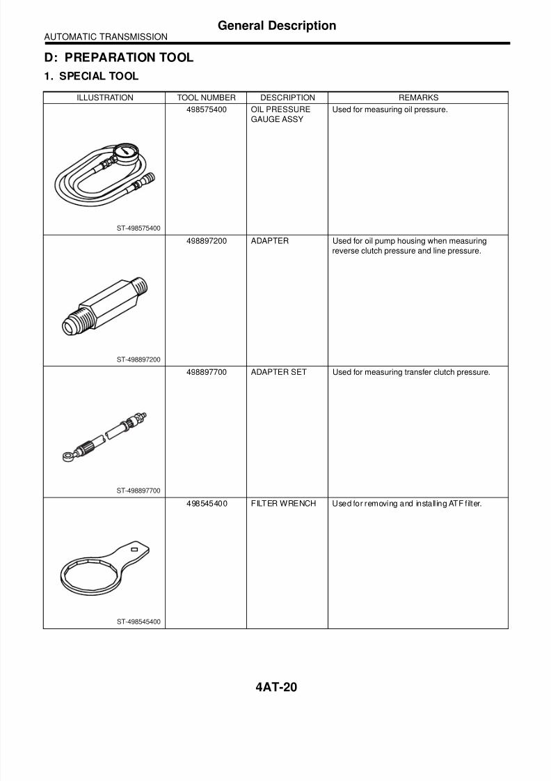
3) Remove the test plug and install the ST instead.ST 498897200 OIL PRESSURE GAUGE

ADAPTER

4) Connect the ST1 with ST2.ST1 498897200 OIL PRESSURE GAUGE

ADAPTERST2 498575400 OIL PRESSURE GAUGE

ASSY5) Check for duty ratio changes by adjusting the ac-celeration pedal position using Subaru Select Mon-

itor.

(A) Test plug

AT-00020(A)

Standard line pressure

Range posi-

tion

Line pres-

sure duty

ratio (%)

Throttle

valve angle

Line pressure

kPa (kg/cm2, psi)

Manual

mode (2nd)25 — 35 Full open

1,000 — 1,300

(10.2 — 13.3,

145 — 189)

R 15 — 25 Full open

1,500 — 1,850

(15.3 — 18.9,

217 — 268)

D 35 — 43 Full closed

500 — 800

(5.1 — 8.2,

73 — 116)

8/12/2019 leg04_trans_02-1

http://slidepdf.com/reader/full/leg04trans02-1 40/484AT-39

AUTOMATIC TRANSMISSIONTransfer Clutch Pressure Test

8. Transfer Clutch PressureTest

A: INSPECTIONCheck the transfer clutch pressure in accordancewith the following chart in the same manner as withline pressure. <Ref. to 4AT-38, Line Pressure

Test.>ST 498897700 OIL PRESSURE ADAPTER

SETST 498575400 OIL PRESSURE GAUGE

ASSY

NOTE:• Before setting in FWD mode, install the sparefuse on FWD mode switch. (MPT model)

• MTP model

• VTD model

• If no oil pressure is produced or if it does notchange in AWD mode, the control valve body maybe malfunctioning. If oil pressure is produced inFWD mode, the same problem as AWD mode oc-curs.

(A) Test plug

(A) Test plug

AT-00021

( A )

AT-00022

(A)

Range

position

ON

Duty

ratio

(%)

Accelera-

tion pedal

position

(%)

Standard transfer clutch

pressure

kPa (kg/cm2, psi)

AWD modeFWD

mode

Manual

mode

(2nd)

95

Fully

opened:

100

1,000 — 1,200

(10.2 — 12.2,

145 — 174)

 —

60

Adjust

ON Duty

ratio to

60%.

500 — 700

(5.1 — 7.1,

73 — 102)

 —

 —Fully

closed: 0 — 0 (0, 0)

N or P 5Fully

closed: 00 —

8/12/2019 leg04_trans_02-1

http://slidepdf.com/reader/full/leg04trans02-1 41/484AT-40

AUTOMATIC TRANSMISSIONAutomatic Transmission Assembly

9. Automatic Transmission As-sembly

A: REMOVAL1) Set the vehicle on a lift.2) Fully open the front hood and support with hoodstay.

3) Disconnect the ground cable from battery.4) Remove the air intake duct.<Ref. to IN(H4SO 2.0)-9, REMOVAL, Air IntakeDuct.>5) Remove the air intake chamber.<Ref. to IN(H4SO 2.0)-8, REMOVAL, Air IntakeChamber.>6) Remove the air cleaner case stay.

7) Disconnect the following connectors.(1) Transmission harness connectors

(2) Transmission ground terminal8) Remove the starter.<Ref. to SC(H4SO 2.0)-6, REMOVAL, Starter.>9) Remove the pitching stopper.

10) Separate the torque converter clutch from driveplate.

(1) Remove the V-belt covers.(2) Remove the service hole plug.(3) Remove the bolts which hold torque con-verter clutch to drive plate.(4) Insert the wrench to crank pulley bolt, and

then remove all the bolts with slightly rotatingcrank pulley.

CAUTION:Be careful not to drop bolts into torque convert-er clutch housing.

11) Install the ST to converter case.ST 498277200 STOPPER SET

12) Remove the ATF level gauge.

NOTE:Plug the opening to prevent entry of foreign parti-cles into transmission fluid.

13) Remove the throttle body. <Ref. to FU(H4SO2.0)-10, REMOVAL, Throttle Body.>

AT-01327

AT-01328

AT-01329

AT-00102

AT-00804

ST

AT-01330

8/12/2019 leg04_trans_02-1

http://slidepdf.com/reader/full/leg04trans02-1 42/484AT-41

AUTOMATIC TRANSMISSIONAutomatic Transmission Assembly

14) Drain the engine coolant by approx. 2 2 (2.1US qt, 1.8 Imp qt). (Model with ATF cooler withwarmer function)15) Disconnect the ATF cooler inlet and outlet hos-es from ATF cooler pipes.

16) Disconnect each hose from warmer cock as-sembly.

17) Remove the ATF cooler with warmer functionfrom transmission body, and then secure it to vehi-cle body by wire, etc.. Select the place not to pre-

vent transmission from being replaced. (Model withATF cooler with warmer function)

18) Remove the warmer cock assembly. (Modelwith ATF cooler with warmer function)

19) Remove the bracket for warmer cock assem-bly. (Model with ATF cooler with warmer function)

20) Remove the pitching stopper bracket.21) Set the ST.ST 41099AC000 ENGINE SUPPORT ASSEM-

BLY

22) Remove the bolts which hold upper side oftransmission to engine.

23) Lift-up the vehicle.24) Remove the under cover.

AT-02171

AT-02163

AT-02164

AT-02165

AT-02166

AT-02167

ST

AT-00106

8/12/2019 leg04_trans_02-1

http://slidepdf.com/reader/full/leg04trans02-1 43/484AT-42

AUTOMATIC TRANSMISSIONAutomatic Transmission Assembly

25) Remove the front, center and rear exhaustpipes and muffler.<Ref. to EX(H4SO 2.0)-7, REMOVAL, Front Ex-haust Pipe.> <Ref. to EX(H4SO 2.0)-11, REMOV-AL, Rear Exhaust Pipe.> <Ref. to EX(H4SO 2.0)-13, REMOVAL, Muffler.>26) Remove the heat shield cover.

27) Remove the ATF drain plug to drain ATF.

28) Disconnect the ATF cooler hoses from pipes oftransmission side, and remove the oil charge pipe.(Model without ATF cooler with warmer function)

29) Remove the propeller shaft.<Ref. to DS-10, REMOVAL, Propeller Shaft.>30) Remove the shift select cable.<Ref. to CS-12, REMOVAL, Select Cable.>31) Remove the brackets (two) which hold frontstabilizer.

32) Remove the bolt securing ball joint of front armto housing.

33) Pull out the front drive shaft from transmission.(1) Using a tire lever or a pinch bar, etc., pull outthe front drive shaft until its joint facing to trans-mission can move smoothly.

NOTE:Place cloth between tire lever or pinch bar and

transmission in order to avoid damaging the sideretainer of transmission.

(2) Hold the transmission side joint portion offront drive shaft by hand and extract the housingfrom the transmission by pressing it outside soas not to stretch the boot.

34) Remove the bolts which hold the clutch hous-ing cover.35) Remove the bolts which hold lower side oftransmission to engine.

36) Place the transmission jack under transmis-sion.

NOTE:Make sure that the support plates of transmission

 jack don’t touch the oil pan.

(A) Oil pan

(B) ATF drain plug

AT-01331

AT-01332

(B)

(A)

AT-01333

AT-00809

AT-00108

8/12/2019 leg04_trans_02-1

http://slidepdf.com/reader/full/leg04trans02-1 44/484AT-43

AUTOMATIC TRANSMISSIONAutomatic Transmission Assembly

37) Remove the transmission rear crossmemberfrom the vehicle.

38) Fully contract the engine support while lower-ing the transmission jack gradually, and tilt the en-gine backward.

NOTE:Contract the support until the clearance betweenfront crossmember and torque converter case be-

comes approx. 10 mm (0.39 in).39) Remove the transmission.

CAUTION:Remove the transmission and torque converteras a unit from engine.

40) Remove the rear cushion rubber from transmis-sion assembly.

B: INSTALLATION1) Replace the differential side oil seal with a newone.

NOTE:When a new oil seal has been installed, the re-placement is not required.

2) Install the rear cushion rubber to transmissionassembly.

Tightening torque: 39 N ⋅ m (4.0 kgf-m, 29 ft-lb) 

3) Install the ST to converter case.

ST 498277200 STOPPER SET

4) Install the transmission onto engine.(1) Lift up the transmission gradually using atransmission jack.

(2) Engage them at splines.(3) Turn the screws of engine support whileraising the transmission jack gradually, and tiltthe engine forward.

5) Install the transmission rear crossmember.

Tightening torque: T1: 35 N ⋅ m (3.6 kgf-m, 26 ft-lb) T2: 70 N ⋅ m (7.1 kgf-m, 51 ft-lb) 

6) Take off the transmission jack.7) Tighten the bolts which hold the lower side oftransmission to engine.

AT-01334

AT-00109

AT-00103

ST

AT-00109

AT-01335

T2   T2T1

8/12/2019 leg04_trans_02-1

http://slidepdf.com/reader/full/leg04trans02-1 45/484AT-44

AUTOMATIC TRANSMISSIONAutomatic Transmission Assembly

Tightening torque: 50 N ⋅ m (5.1 kgf-m, 36.9 ft-lb) 

8) Screw the bolts for the clutch housing cover.9) Lower the lift.10) Connect the engine and transmission.

(1) Remove the ST from converter case.

NOTE:When removing the ST, be careful not to drop it into

converter case.ST 498277200 STOPPER SET

(2) Install the starter.<Ref. to SC(H4SO 2.0)-6, INSTALLATION,Starter.>(3) Tighten the bolts which hold the upper sideof transmission to engine.

Tightening torque: 50 N ⋅ m (5.1 kgf-m, 36.9 ft-lb) 

11) Install the torque converter clutch to drive plate.(1) Tighten the bolts which hold torque convert-er clutch to drive plate.(2) Insert the wrench to crank pulley bolt, and

then tighten all bolts while slightly rotating thecrank pulley.

Tightening torque: 25 N ⋅ m (2.5 kgf-m, 18.1 ft-lb) 

(3) Fit the plug to service hole.(4) Install the V-belt cover.

12) Remove the ST.

13) Install the warmer cock assembly bracket.(Model with ATF cooler with warmer function)

Tightening torque: 16 N ⋅ m (1.6 kgf-m, 11.6 ft-lb) 

14) Install the warmer cock assembly. (Model withATF cooler with warmer function)

AT-00108

AT-00106

AT-00102

AT-02167

ST

AT-02166

8/12/2019 leg04_trans_02-1

http://slidepdf.com/reader/full/leg04trans02-1 46/484AT-45

AUTOMATIC TRANSMISSIONAutomatic Transmission Assembly

Tightening torque: T1: 6.4 N ⋅ m (0.65 kgf-m, 4.7 ft-lb) T2: 15 N ⋅ m (1.5 kgf-m, 10.8 ft-lb) 

15) Connect each hose to warmer cock assembly.(Model with ATF cooler with warmer function)

16) Install the pitching stopper bracket and bracket(Model with ATF cooler with warmer function).

Tightening torque: 41 N ⋅ m (4.2 kgf-m, 30.4 ft-lb) 

17) Install the ATF cooler with warmer function totransmission body. (Model with ATF cooler withwarmer function)

Tightening torque: 23 N ⋅ m (2.3 kgf-m, 16.6 ft-lb) 

18) Connect the ATF cooler inlet and outlet hosesto ATF cooler pipes. (Model with ATF cooler withwarmer function)

19) Install the throttle body. <Ref. to FU(H4SO2.0)-10, INSTALLATION, Throttle Body.>20) Install the pitching stopper.

Tightening torque: T1: 50 N ⋅ m (5.1 kgf-m, 37 ft-lb) 

T2: 58 N ⋅ 

m (5.9 kgf-m, 43 ft-lb) 

(A) Pitching stopper bracket

(B) Bracket (Model with ATF cooler with warmerfunction)

AT-02168

T1

T2

AT-02163

AT-02169

(A)

(B)

AT-02164

AT-02171

AT-01346

T1T2

8/12/2019 leg04_trans_02-1

http://slidepdf.com/reader/full/leg04trans02-1 47/484AT-46

AUTOMATIC TRANSMISSIONAutomatic Transmission Assembly

21) Lift-up the vehicle.22) Replace the snap ring of front drive shaft with anew one.23) Apply grease to the oil seal lips.24) Install the ST to side retainer.ST 28399SA010 OIL SEAL PROTECTOR

25) Align the spline of front differential shaft to thatof differential bevel gear for insertion, and removethem using ST.ST 28399SA010 OIL SEAL PROTECTOR26) Insert the front drive shaft into transmission se-curely by pressing the front housing from outside.

27) Install the ball joint into housing.28) Tighten the attachment bolts.

Tightening torque: 50 N ⋅ m (5.1 kgf-m, 36.9 ft-lb) 

29) Install the stabilizer to crossmember.

NOTE:• Install the bushing (on front crossmember side)while aligning it with the paint mark on stabilizer.

• Ensure the bushing and stabilizer have the sameidentification colors when installing.

30) Always tighten the rubber bushing locationwhen wheels are in full contact with the ground andvehicle is curb weight.

Tightening torque: 25 N ⋅ m (2.5 kgf-m, 18.1 ft-lb) 

31) Install the shift select cable onto select lever.<Ref. to CS-13, INSTALLATION, Select Cable.>32) Install the oil charge pipe, and connect the ATFcooler hoses to pipe. (Model without ATF coolerwith warmer function)

33) Install the oil charge pipe. (Model with ATFcooler with warmer function)34) Install the propeller shaft.<Ref. to DS-11, INSTALLATION, Propeller Shaft.>35) Install the heat shield cover.

36) Install the rear exhaust pipe and muffler as-sembly.

AT-00110ST

AT-00111

AT-00809

(1) Identification mark on stabilizer

(2) Bushing identification color

FS-00050

AT-01333

AT-01331

8/12/2019 leg04_trans_02-1

http://slidepdf.com/reader/full/leg04trans02-1 48/48


Recommended