The serial number plate is fitted to the chassis beam at the front of the spreader. In case of correspondence and ordering of spare parts, kindly state the completeserial number of your spreader. Complete the blanks below with this informationto reference when calling.
**You MUST read this manual fully prior to starting work.**
Thank you for your decision to purchase a Lely IndustrialBroadcast Spreader. The spreader has been designed and builtto do the very best job possible under many application circumstances.
This Operator's Manual is meant for personnel that are operatingthe spreader and are responsible for its daily maintenance.Following it carefully can greatly increase the performance and lifeof the spreader.
The Dealer is required to confirm that an Operator’s Manual iswith the spreader. Upon retail sale the Dealer shall review theOperator’s Manual and instruct the customer on SAFE operationand proper maintenance of the spreader.
Your Dealer is authorized to service the spreader and is requiredto stock wear parts. If they are unable to help please go to ourweb site and find the next closest dealer to you.www.lelyusa.com, LOCATOR or feel free to contact Lely at 888-245-4684.
Instructions for YOUR SAFETY and/or that of others aremarked in the margin by a warning triangle with exclamationmark. These instructions should be observed with particularCARE & ATTENTION.
Instructions which may lead to serious machine damage incase of non-compliance or incorrect use are marked in themargin by an exclamation mark.
The machine described in this manual may contain componentswhich do not form part of the standard equipment but are available as optional extras. This is not made clear in all cases,because standard specifications may differ from country to country.
Furthermore, machines and optional extras may be adjusted tospecific regional conditions while they are also subject to continuing research and innovation. For this reason, the specifications of your machine may not be exactly like the pictures in this manual.
2
Known Worldwide For Accuracy & Dependability
SAFETY INSTRUCTIONS
NEVER service spreader while in operation. Stop engine and moving parts before attempting to service, adjust, clean or lubricate the spreader.
A careful operator is the best operator. Most accidents can andwill be avoided by observing all precautions. Read and observethe following precautions before operating this Spreader. It willhelp PREVENT ACCIDENTS. Spreaders should be operated onlyby those who have read the Owners Manual, and are thus quali-fied to do so.
• Use the spreader only for the purpose for which it was designed.
• Do not exceed 9 mph when operating or towing machine.
• Follow all prevailing safety regulations, including those laid down in this manual displayed on the spreader decals.
• The spreader should be operated by authorized persons only.
• Keep hands and feet CLEAR of unit while in operation.
• Be alert, OBSERVE and OBEY all safety/warning decals.
• Make sure that ALL safety guards and protective devices are in place.
• Do NOT wear loose clothing when operating the Power Take-Off or when near any moving parts.
• Release the pressure in hydraulic systems before starting work on them and before coupling/uncoupling hydraulic hoses.
• Keep other persons CLEAR of the danger zone or spread area while the spreader is in operation. Be sure that people are kept WELL AWAY from the spreader. This is especially important when working along roads and near or on fields that are accessible to the public.
• Always use a tractor with a cab.
• Clear the field of objects that could be thrown up by the spreader.
• Observe the prevailing legislation for public road transport of the spreader.
• Use flashing lights or safety signs, when required.
• Use protective clothing, gloves, and safety glasses where required.
• If any liquid or granular chemicals are to be used in combination with this equipment, carefully read and follow all instructions and directions set forth by the manufacturer as stated on the label of the material.
• Clean the safety decals regularly so that they can be read at all times.
• Do not stand or ride on the spreader.
• Use genuine parts only.
CAUTION: STOP THE PTO AND EJECTOR DISC BEFORELEAVING THE TRACTOR OR VEHICLE TO CHANGE ANY
3
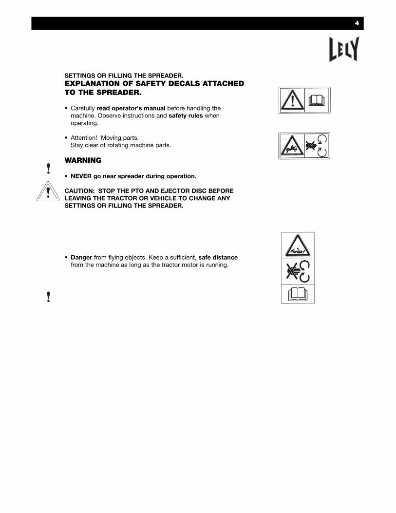
SETTINGS OR FILLING THE SPREADER.EXPLANATION OF SAFETY DECALS ATTACHEDTO THE SPREADER.
• Carefully read operator's manual before handling the machine. Observe instructions and safety rules when operating.
• Attention! Moving parts.Stay clear of rotating machine parts.
WARNING
• NEVER go near spreader during operation.
CAUTION: STOP THE PTO AND EJECTOR DISC BEFORELEAVING THE TRACTOR OR VEHICLE TO CHANGE ANY SETTINGS OR FILLING THE SPREADER.
• Danger from flying objects. Keep a sufficient, safe distancefrom the machine as long as the tractor motor is running.
4
BE ALERT! YOUR SAFETY IS INVOLVED!LIMITED WARRANTY CONDITIONS
Lely USA. Inc. (hereinafter “Company”) warrants all Lely singledisc broadcast spreaders (hereinafter “Spreader”) for a period oftwo (2) years from the date delivered to the original purchaseragainst defective materials and/or workmanship. Any part or partsof the Spreader that in the Company’s judgment shows evidenceof such defects, will be repaired or replaced as the Companyelects, without charge for parts or labor if the defect appearswithin the stated time.
**Warranty shall NOT apply if spreader has not been properlyregistered.
The CUSTOMER is SOLELY responsible for completing the ‘LelyCustomer Warranty Card’ located on the cover of this manual. Nopostage is required.
A. Unapproved Service & Modification* All obligations of the Company under this warranty shall be terminated if:
1. Proper service and operation instructions as outlined inthe Operator’s Manual’ are not followed. *Warranty SHALL NOT apply if operating instructions set forth in the manual have not been fully or correctly followed.
2. Equipment is modified or altered in any way not specifically approved by the Company.*Warranty SHALL NOT apply to spreaders that have been ‘altered’ or ‘modified’ in any way.
3. Serial number plate has been altered, defaced or removed.
4. Ownership is transferred from the original purchaser to any subsequent owner.
B. Accidents & Normal MaintenanceThis warranty covers defective material and workmanship. It does not cover depreciation or damage caused by normal wear, accident, improper maintenance, improper protection, or improper use. The cost of normal maintenance and normal replacement of service items such as grease, oil, tires, tubes, spoons, tines, hoses, etc., shall be paid by the purchaser. Any items considered for warranty, but not manufactured by the Company, will be forwarded by Lely to the original manufacturer for their warranty determination.
C. Warranty ServiceTo obtain warranty service, the purchaser MUST contact their LOCAL authorized Lely Dealer. At the Company’s request such parts are to be returned ‘prepaid’ to Lely USA for
5
inspection and final warranty determination.D. No Representation or Implied Warranty
Neither the Company, nor any company affiliated with Lely, makes any warranties, representation, or promises, expressed or implied, as to the quality or performance of its products other than those set forth above and does not make any implied warranty of merchantability or fitness.
E. Remedies ExclusionThe only remedies the purchaser has in conjunction with the breach, or performance of any warranty on any spreader manufactured by the Company are those set forth above.
F. General1. The Company reserves the right to make improvements or
changes in its equipment at any time without obligation to the Company to install such improvements or changes on equipment previously manufactured by the Company.
2. Neither the Dealer nor the Company personnel have authority to make any representations or promises on behalf of the Company or to modify the terms of limitationsin this warranty in any way.
3. This warranty gives you specific legal rights, and you may
6
7
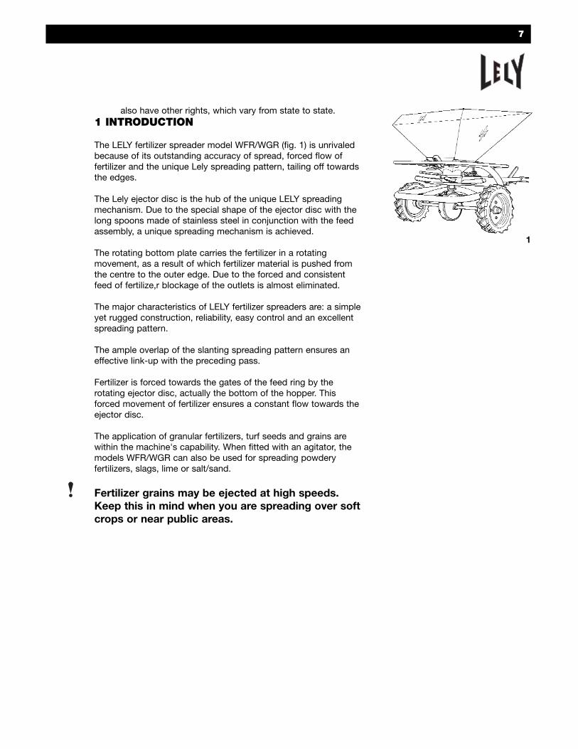
also have other rights, which vary from state to state.1 INTRODUCTION
The LELY fertilizer spreader model WFR/WGR (fig. 1) is unrivaledbecause of its outstanding accuracy of spread, forced flow of fertilizer and the unique Lely spreading pattern, tailing off towardsthe edges.
The Lely ejector disc is the hub of the unique LELY spreading mechanism. Due to the special shape of the ejector disc with thelong spoons made of stainless steel in conjunction with the feedassembly, a unique spreading mechanism is achieved.
The rotating bottom plate carries the fertilizer in a rotating movement, as a result of which fertilizer material is pushed fromthe centre to the outer edge. Due to the forced and consistentfeed of fertilize,r blockage of the outlets is almost eliminated.
The major characteristics of LELY fertilizer spreaders are: a simple yet rugged construction, reliability, easy control and an excellentspreading pattern.
The ample overlap of the slanting spreading pattern ensures an effective link-up with the preceding pass.
Fertilizer is forced towards the gates of the feed ring by the rotating ejector disc, actually the bottom of the hopper. This forced movement of fertilizer ensures a constant flow towards theejector disc.
The application of granular fertilizers, turf seeds and grains are within the machine's capability. When fitted with an agitator, themodels WFR/WGR can also be used for spreading powderyfertilizers, slags, lime or salt/sand.
Fertilizer grains may be ejected at high speeds.Keep this in mind when you are spreading over softcrops or near public areas.
1
2 START UP
2.1 Coupling behind the tractor
The spreader is to be coupled behind the tractor (or truck) in sucha way that the ejector disc is in a horizontal position.
This can be obtained by giving the drawbar the appropriate angle,i.e. position 1, 2, or 3. The gear lever rod must be placed in thecorresponding position (fig. 2).
• If the machine is equipped with a mechanical control of thefeed mechanism; place the control string in the tractor/truckcabin (fig. 3).
• If the machine is fitted with a hydraulic control of the feedmechanism, connect the hydraulic hose to a singleacting tractor spool valve (fig. 4).
2.2 Hopper removal
The hopper can be removed from the frame by lifting the latchlever at the rear of the machine and unhooking the bracket.Before taking the hopper off the frame, it must be lifted slightly atthe rear.
2.3 Operation
Do not exceed 9 mph when operating or towing machine.
A guide for calibration with application and sowing rates is located on page 12.
For accurate spreading, we recommend:
• Double overlap will ensure even distribution (see 5.2).
• Maintaining correct distance between passes.
• Having the spread pattern centralized behind the machine.
• Spreading in the rounds instead of back and forth.
2.4 Cleaning
Easy cleaning of the machine can be done by removing the hopper.
To remove the hopper, the arm or fork of the feedring must betaken out of its hole and rotated away. Then release the hopperlatch, and by slightly lifting the rear of the hopper, tilt it backwards. After this, the feedring can be taken off.
8
2
3
4
9
3 TRANSPORT
Do not exceed 9 mph when operating or towing machine.
• Apply all lighting and warning signals that are required by law.
• For transport on public roads care should be taken that thefront axle pressure is sufficient (fit front weights, if necessary) and that the maximum rear axle pressure is not exceeded.
Transportation is easier to control when the hopper is empty. It istherefore recommended to fill the hopper after arrival in the areato be worked. This also eliminates compacting of fertilizer thatmay occur during transport.
4 MACHINE ADJUSTMENTS
4.1 Output rates
The output rate is determined by the feedring assembly, theworking width, and forward speed. The correct position of thecalibration scale on the feedring assembly can be determined bymeans of calibration charts.
They are based on a speed of 4.5 mph. You can spread at a higher speed, but then the working width must be adapted to thegreater overall spreading width. The quantity spread per acrecould be slightly less.
The quantities listed in the calibration guides are approximate.Due to variable factors, grain coarseness or fineness, density, orspecific gravity of the fertilizer, or humidity, etc., the effective output may differ from the value listed in the guide.
It is therefore advisable to check the output. The spreadingtables indicate average values only.
For more information on output rates, it is recommended toconsult the Calibration Guide for LELY fertilizer spreadersWFR/WGR at the end of this section.
10
4.1.1 Working width
An effective overlap of spreading patterns is obtained if the working width is about 3/4 or .77 of the spreading width (fig. 5).
For most types of granular fertilizer the spreading width isapprox. 52 ft (16 m) at a speed of 4.5 mph. At a faster speed theworking width will change. At the same time the centralized pattern can change. The pattern needs to be centralized thesame distance to the left as it is to the right, measured from thecenter of the spreader.
The correct working width is then .77 x 52 ft (16m) = 40 ft (12m).
Granular fertilizer spread at 5 mph gives a spreading width of 66 ft. Working width would be 3/4 or .77 x 66 = 50 ft.
At a speed of 5 mph the quantity spread per acre is about 10%less then indicated for 4.5 mph. The calibration guide gives average figures only.
4.1.2 Setting of output rates
Fertilizer outputs per acre depend upon: working width, forwardspeed, type of fertilizer, and the position of the stop on the calibration scale.
Stop positions for output rates required can be established byconsulting the calibration guide (p. 12).The quantities listed in the output charts are approximate. Size,shape, mix, and weight of the fertilizer grains may vary accordingto the fertilizer brand and/or production batch.
It is therefore recommended to check the output rate accordingto "4.1.3 Check of output rate" included in this manual.
Example I:
• Fertilizer: X = large grain or granular• Required output rate: 330 lb/acre• Working width = 40 ft (12 m)• Forward speed = 4.5 mph
The calibration guide for large/granular fertilizers indicates that position 7 of the calibration stop (fig. 6) gives an output of 302lb/acre, while an output of 364 lb/acre is obtained at setting 8.
Working Width Spreading Width
5
6
A
B
CAUTION: STOP THE PTO ANDEJECTOR DISC BEFORE LEAVINGTHE TRACTOR OR VEHICLE TOCHANGE ANY SETTINGS OR FILLING THE SPREADER.
An intermediate position will have to be used.The output difference between positions 7 and 8 is 302 - 364= 62 lb/acre. Each consecutive intermediate position accountsfor an increase in output of approx. 1/4 or .25 x 62 lb/acre.
The second intermediate position B gives the closest approximation of the output required.
It is possible to operate at a speed and working width other thanthe one listed in the output rate charts.
When operating at another working width than the one listedin the chart, do not fail to carry out a check of the output rate(see section 4.1.3).
11
POSITION7
Intermediate PositionsA
POSITION8B C
302 317.5 364333 348.5
12
Position of calibration scale
1
2
3
4
5
6
7
8
9
10
LARGE GRAINS(mixed fertilizers,granulars, super-phoshate)Position offeedring armSector I or IIWorking Width39 ft.
9
21
54
91
136
203
302
364
394
415
SMALL GRAINS(Prills etc.)Position offeedring armSector I or IIWorking width 39 ft.
20
30
77
144
224
336
439
531
573
597
POTASH 40%Position offeedring armSector IIIWorking width20 ft.
-
-
36
70
105
139
205
273
371
413
SLAGS + 6%water Position offeedring armSector IVWorking width16 ft.
27
79
145
224
300
376
517
642
667
679
CALIBRATION GUIDEbased on a tractor speed of 4 1/2 miles per hour
Position of calibration scale
1
2
3
4
5
6
7
8
9
10
LARGE GRAINSSector IIWorking width20 ft (6 m)
18
42
108
182
272
406
604
728
788
830
SMALL GRAINSSector IIWorking width20 ft (6 m)
40
60
154
288
448
672
878
1062
1146
1194
CALIBRATION GUIDEbased on a working width of 20 feet (6 m)
and a tractor speed of 4 1/2 miles (7 km) per hour
7
6
7
8
910
Holes 6-10 are used for side spreading and is refered to in section 4.4.
4.1.3 Checking output rate
Check the calibration stop recommended in the Calibration Guideby filling the hopper with a known small quantity of fertilizer andmeasuring distance covered to empty the hopper.
Multiply the quantity of fertilizer spread by the Distance Chart (below) by the number of yards run (this number is predetermined by the working width previously determined i.e. 39 ft = 372 yards).
Divide by the distance actually covered.
The answer will be the quantity of fertilizer actually spread peracre.
Example:
• Rate required = 300 lbs/acre• Speed = 4.5 mph• Calibration stop = 7• Working width = 39 ft• Actual applied = 110 lbs.• Actual distance covered = 142 yards
In order to obtain the output required, the feed assembly shouldbe adjusted to slightly higher than 7 position.
13
110 x 372142
= 288 lbs/acre
Width of Spread
18 ft.
21 ft.
24 ft.
27 ft.
30 ft.
33 ft.
36 ft.
39 ft.
42 ft.
45 ft.
48 ft.
50 ft.
Yards Run Per Acre
806 yards
691 yards
605 yards
538 yards
484 yards
440 yards
403 yards
372 yards
346 yards
323 yards
303 yards
290 yards
Distance Chart
actual applied x yards rundistance actually covered
= quantity actually spread in lbs/acre
9
A
B
REMARKS
If tractor wheel slip occurs, the quantity spread per acre willincrease.
The correct calibration and correct distribution pattern are onlyobtained when fertilizer reaches the ejector disc through the threegates of the feedring. Any multi-sized/ density material and leakage must be adjusted for. The feedring gates should not bealtered in any way.
The Agitator (2320104600) should NOT be used when spreading granular fertilizer.
4.2 Control
4.2.1 Mechanical control
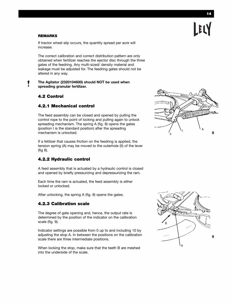
The feed assembly can be closed and opened by pulling thecontrol rope to the point of locking and pulling again to unlockspreading mechanism. The spring A (fig. 8) opens the gates (position I is the standard position) after the spreading mechanism is unlocked.
If a fetilizer that causes friction on the feedring is applied, the tension spring (A) may be moved to the outerhole (II) of the lever (fig 8).
4.2.2 Hydraulic control
A feed assembly that is actuated by a hydraulic control is closedand opened by briefly pressurizing and depressurizing the ram.
Each time the ram is actuated, the feed assembly is eitherlocked or unlocked.
After unlocking, the spring A (fig. 8) opens the gates.
4.2.3 Calibration scale
The degree of gate opening and, hence, the output rate isdetermined by the position of the indicator on the calibrationscale (fig. 9).
Indicator settings are possible from 0 up to and including 10 byadjusting the stop A. In between the positions on the calibrationscale there are three intermediate positions.
When locking the stop, make sure that the teeth B are meshedinto the underside of the scale.
14
8III A
4.3 Fork/arm position
The position of the spreading pattern behind the spreader isdetermined by the position of the feedring assembly (fork/armposition) When the fork is turned clockwise, the spreadingpattern will move to the left, when viewed in the direction of travelor from behind the tractor (fig. 10).
By adjusting the fork, a symmetrical pattern behind the tractorcan be ensured.
A general rule of thumb is: the coarser the material to be spread,the higher the fork setting (fig. 10 & 11).
The correct position of the feedring assembly should be determined by experiment. The spreading pattern should be centrally located behind the broadcaster. Place the fork in one ofthe positions listed above by way of guideline. If, for example, thespreading pattern deviates to the right, this can be corrected bymoving the fork of the feedring one hole to the left.
When starting the spreading operation, check for equal applica-tion on the left and right side. Adjust if necessary. Positions 6 – 10 are used for side or headland spreading. For furtherdetails please refer to "4.4.1 Adjustment for side/headlandspreading".
Differences in size and weight of various fertilizers, grains orseeds may cause the spreading pattern to not be centrallybehind the broadcaster.
15
11
Material Fork setting
Lime, slags 1-3 III-V
Lime nitrate 40% 2-4 IV-II
Granulars 3-5 III-V
Cereals/rice 4-5 II-I
10
6
7
8
910
4.4 Side/Headland spreading
4.4.1 Adjustment
The fork of the feedring assembly should be set in position 6 – 10(fig. 12). Move it in a clockwise direction to a suitable hole in thesideplate to obtain side delivery.
Select position 6 – 8 for powdery fertilizers.Select position 7 – 9 for coarsely granulated fertilizers.Select position 8 – 10 for the remaining materials.
Spreading takes place from the tractor wheel track towardsthe side area. The side/headland spreading pass should be carried out at a distance from the side of 2/3 (.67) full field working width.
Check correct position of spreading pattern, on the left sidebehind the spreader (fig. 13). Adjust, if necessary by means ofa different fork/arm hole position.
The fertilizer or other material has to remain just within the sidearea desired. If necessary, adjust your speed in order to ensurethat the spreading pattern just reaches the edge of the turf orfield. 4.5 mph is recommended speed for proper application rate.
The output rate for side/headland spreading should be 40% ofthe quantity required during regular turf or field application.Subsequent passes or runs are then carried out in the normalmanner with the full feed rate and the feedring set to spread centrally (fig 14).
The tractor wheel track for the side/headland pass is situated at2/3 (.67) of the 39 ft working width = 26 ft from the side. The output rate has to be adjusted at 40% of 560 lb/acre = 224 lb/acre.
From the chart for small granular it can be inferred that theCalibration stop should be adjusted to position 5.
CAUTION: STOP THE ENGINE AND EJECTOR DISC BEFORELEAVING THE TRACTOR OR VEHICLE TO CHANGE ANY SETTINGS OR FILLING THE SPREADER.
16
12
6
7
8
910
13
S
K
K = side/headland spreadingS = first pass full field
14
8 ft.
Normal spreading pattern
Pattern side-delivery
Total spreading pattern
17
5 Operating the machine
• Fertilizer granular may attain high speeds leading toinjuries and damage of soft crops.
• High Speed Fertilizer: do not allow people or animals to approach a spreader in operation with a radius of at least 100 ft (30 m). Reduce the spreading width for spreading over soft crop!
• Stop the tractor engine before exiting. Do notallow anyone to come near the machine while the disc is still rotating.
First carry out the check and maintenance duties if thespreader is new. For more details refer to "6 Maintenance".
At user's choice, side/headland or full spreading may be carriedout first (fig.15).
Listed in the survey below you find, for a number of workingwidths, the distance between the plot separation and tractor/vehicle wheel track, both for side spreading and full fieldoperation.
15
S
K
K = side/headland spreadingR = working widthS = first pass full field
R
WorkingWidth
Distance from plot side (ft)
Headland Spreading First Pass
K = .67 x R SR
10.5132633
1417
34.542.5
16204050
18
5.1 Full field operation
It is up to you to start with side/headland spreading or with a fullfield operation.
For full field spreading circular passes are preferred to drivingup and down (fig.16). When driving circular passes, spreadingdifferences will be compensated by the next run or adjoiningspreading pattern.
When driving up and down on turf applications, spreading differences are increased. It is important to know your WorkingWidth and ensure proper overlap to compensate for the greaterdeviation that occurs using this method.
5.2 Double overlap
If a particularly accurate spreading pattern is required, doubleoverlap spreading can be carried out.
Half the normal working width is then used.
Carry out spreading all over the plot by driving up and down(fig. 17).
As spreading is effectively carried out twice, the feedassembly has to be set at half the output required.
Example:
• Output required = 430lb/acre• Normal working width = 40 ft (12 m)• When applying double overlap: drive up and down with a 20 ft
(6 m) distance between the passes.• Set feedring assembly at an output of 215 lb/acre.
Sometimes it is desirable to double the quantity spread per acre.Use a working width 1/2 the normal working width and followingthe above Double Overlap pattern. Do not adjust feedring output.
Spreading round and round is preferable to spreading up anddown when it comes to accurate distribution.
16
K
K = headland spreadingS = first pass full field
17K = headland spreadingS = full field spreading
S
KS
19
5.3 Check of spreading width
An effective link-up of spreading patterns is obtained if theworking width is 3/4 (.77) of the spreading width (fig. 18).
If there is a substantial difference, the following checksshould be carried out:
- the working width was measured correctly.
- damage or wear and tear of spinner discs, spoons or feed device.
- the drive was fully engaged.
- the correct Calibration Guide was used.
There may also be differences (grain shape, size, and weight)between the fertilizer applied and the material used duringspreading tests for establishing the Calibration Guide(information could be from another quality or brand).
5.4 Check of output rate
The quantities listed in the output charts are approximate.Size, shape and weight of the granular may vary accordingto the fertilizer brand and/or production batch. The effectiveoutput may also be affected by other circumstances (forexample, air humidity).
It is therefore recommended to check the rate of output.Or else the following procedure can be applied.
- Put a weighed-out quantity of fertilizer in the hopper.
- This quantity should cover a distance of at least 300 ft (91 m).
- Empty the hopper by operating at 4.5 mph forward speed.
- Measure the distance of the fertilizer application.
- Weigh the remainder of fertilizer in the hopper, (if hopper has not been emptied).
- Determine the output of fertilizer per acre by means of the formula below:
43,560 x output (lb)working width (ft) x length covered (ft)
= lb/acre
Working Width Spreading Width
18
20
Example
Fertilizer spreader filled with 150 lbs fertilizer.
Working width = 40 ft (12 m)
Distance covered = 500 ft (154 m)
Balance of fertilizer = 52 lbs
Output =
If the effective output differs very much from the value listedin the calibration guide, this may be due to any of the followingcauses:
- large difference between the fertilizer applied and the material for which the chart is applicable;
- incorrect adjustment of the calibration stop on the feedring assembly;
- non-compliance with the forward speed on which the output rate adjustment is based;
- clogging of feed openings ( example – lumps or clods in the fertilizer).
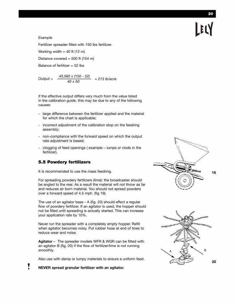
5.5 Powdery fertilizers
It is recommended to use the mass feedring.
For spreading powdery fertilizers (lime): the broadcaster shouldbe angled to the rear. As a result the material will not throw as farand reduces air born material. You should not spread powdersover a forward speed of 4.5 mph. (fig 19).
The use of an agitator base - A (fig. 20) should effect a regularflow of powdery fertilizer. If an agitator is used, the hopper shouldnot be filled until spreading is actually started. This can increaseyour application rate by 10%.
Never run the spreader with a completely empty hopper. Refillwhen agitator becomes noisy. Put rubber hose at end of tines toreduce wear and noise.
Agitator – The spreader models WFR & WGR can be fitted withan agitator B (fig. 20) if the flow of fertilizer/lime is not runningsmoothly.
Also use with damp or lumpy materials to ensure a uniform feed.
NEVER spread granular fertilizer with an agitator.
BA
19
43,560 x (150 - 52)40 x 50
= 213 lb/acre
20
21
5.6 Slags
Slags can be spread effectively if they are mixed with 6% water (6quarts of water for 220 lbs of slags) prior to spreading. Startspreading immediately after the hopper has been filled with mixture. Satisfactory results can be obtain by adding a few pintsof water into the hopper with each bag of slags. The agitator willthen produce a mixture. Make sure that it does not reach thewalls of the hopper. The sides must be kept dry.
An agitator ensures a smooth flow towards the feed openings.
In addition to the above, see "5.5. Powdery fertilizers" for theapplication of slag.
5.7 Seeds
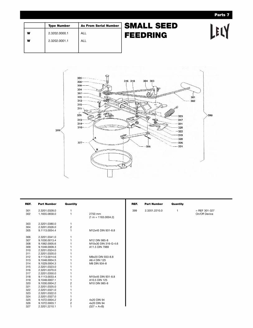
Lely spreaders can also be used for the application of seeds.For spreading small seeds, a special small seed feedringis available.
The Calibration Table for Cereals & Seed provides output for various types.
NOTE: Certain types of material (e.g. very fine fertilizers, turf orrice) may force their way to the spinner disc through the spacebetween the hopper neck and the feedring assembly. This type ofspillage can be avoided by fitting a length of self adhesive foaminsulation on the hopper neck above the feedring.
Broadcasting Cereals & Seeds – The Lely fertilizer spreader isalso suitable for broadcasting all kinds of seeds without modification or using the small seed feedring per the followingchart.
S = small seed feedrings for sowing small seedsF = standard type feedrings as for fertilizer* = for these setting see below
Note: When using a very small quantityof seed, it is recommended that potashor sand be mixed with the seed.
7
6
7
8
910
Holes 6-10 are used for side spreading and is refered to in section 4.4.
23
6 MAINTENANCE
Proper machine servicing is necessary to maintain reliable and safe working conditions.
6.1 Maintenance after operation
All parts should be thoroughly cleaned after each days use andoiled prior to storage. Regular maintenance means a longer life.
- Clear the hopper of fertilizer residue, if any.
- After jet-cleaning the machine thoroughly, allow rotation of the spinner discs to ensure that the water is swept away.
Take care that nobody is in the danger zone!
- Grease the machine with a rust preventive.
- Check the condition of the spinner discs and spoons.Damaged or worn spinner discs and/or spoons may affectthe spreading pattern. Replace if worn.
When fitting spoons, tighten the bolts with a torque of 11 ft-lb as a maximum.
- Check the oil level of the gear drive.• When the machine/gearbox is kept in a horizontal position,
the oil level should be exactly up to the bottom side of the hole for the filling plug.
- If an agitator is used, it should be cleaned daily upon completion of the operation. Remove the agitator from itsshaft and grease it.
- Check the oil level in the gearbox frequently. For moreinformation, please refer to "6.3 Change of oil".
- Check the machine for damage and flaws.
- Check the functioning and adjustment of the feedring assembly.
6.2 Intermittent maintenance
Intermittent maintenance has to be carried out:
• at the start of the spreading season;
• before prolonged storage of the machine;
• when the machine is used extensively during the season;
• to prolong the lifetime of the machine.
- Clean the machine thoroughly immediately after use andlubricate it with oil or some other rust preventive. For proper cleaning of the feed assembly, the hopper can be tilted. For this purpose, the fork of the feed assembly should be turned toa section without holes.
WFR/WGR: disengage the hopper latch. The hopper can now belifted from the chassis in its entirety.
24
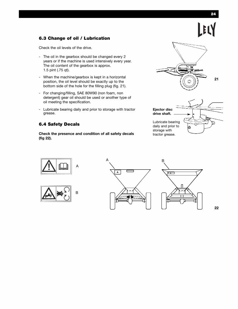
6.3 Change of oil / Lubrication
Check the oil levels of the drive.
- The oil in the gearbox should be changed every 2 years or if the machine is used intensively every year. The oil content of the gearbox is approx. 1.5 pint (.75 qt).
- When the machine/gearbox is kept in a horizontal position, the oil level should be exactly up to the bottom side of the hole for the filling plug (fig. 21).
- For changing/filling, SAE 80W90 (non foam, non detergent) gear oil should be used or another type of oil meeting the specification.
- Lubricate bearing daily and prior to storage with tractorgrease.
6.4 Safety Decals
Check the presence and condition of all safety decals(fig 22).
21
A
B
A B
22
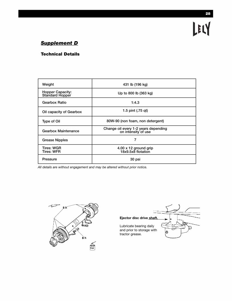
Ejector discdrive shaft.
Lubricate bearingdaily and prior tostorage with tractor grease.
25
Supplement A
CONDENSED INSTRUCTIONS
Study the instruction manual carefully before operating spreader.
- Select the required working width, forward speed andoutput/acre. Consult the calibration guide for the corresponding adjustment of the feedring assembly.
When working at a width not listed in the table, the "setting value" should be used.
When working with a double overlap: adjust at half the output rate required.
For side/headland spreading: adjust at 40% of the required (full field) output.
- For the application of powdery fertilizers, tilt spreader backwards away from tractor.
- The position of the feedring assembly (fork position) in respectto the machine determines the position of the spreadingpattern behind the spreader (fig. 23).
- Move the arm/fork to a hole that centralizes your spread pattern.
- By moving the fork position clockwise, the spreading patternwill move to the left seen from the direction of travel.
- For side/headland spreading move clockwise to the 5 far side holes (fig 24).
- A general rule of thumb is: the coarser the fertilizer material, the higher the position number of the fork.
24
23
6
7
8
910
26
Supplement B
OPTIONS
Feedring assembliesThe spreader is supplied with a remote control Standardfeedring assembly, controlled from the tractor cab by means of arope.
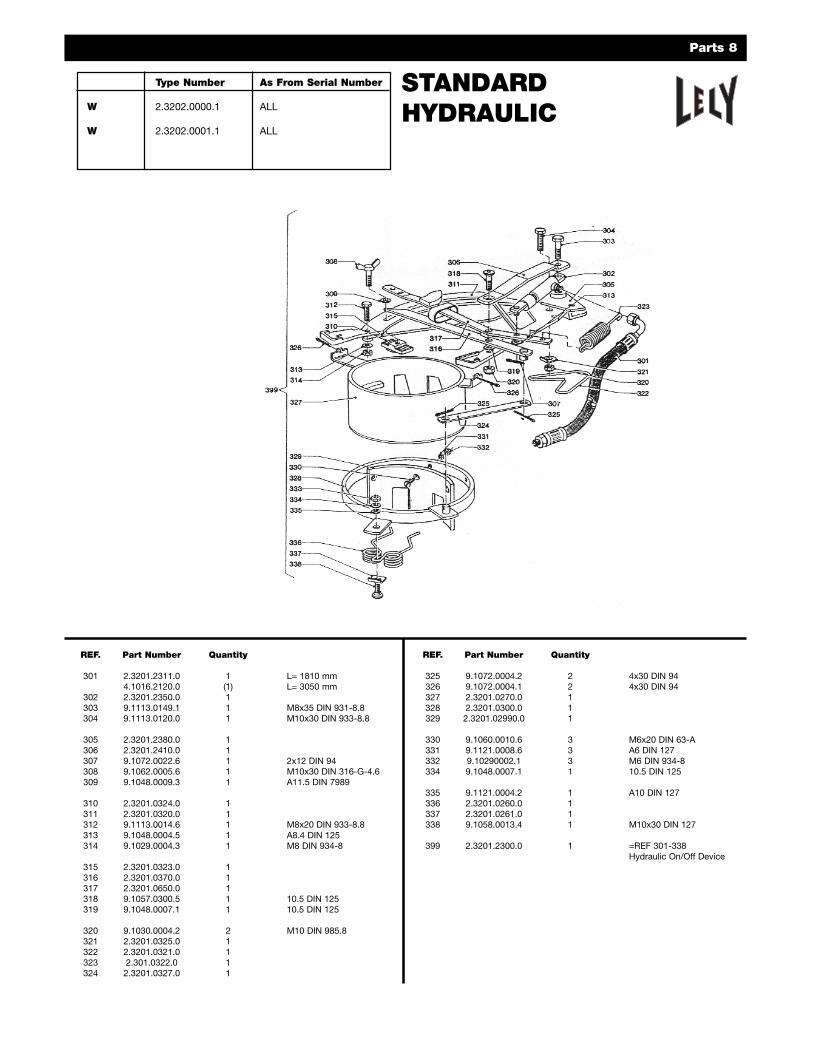
A Standard Hydraulic feedring assembly is available as an option.It lets the operator open and close the feedring using a switchconnected to the tractor’s hydraulic system.
If fine seeds need to be spread, a Small Seed Feedring assemblycan be used. This device has small output openings.
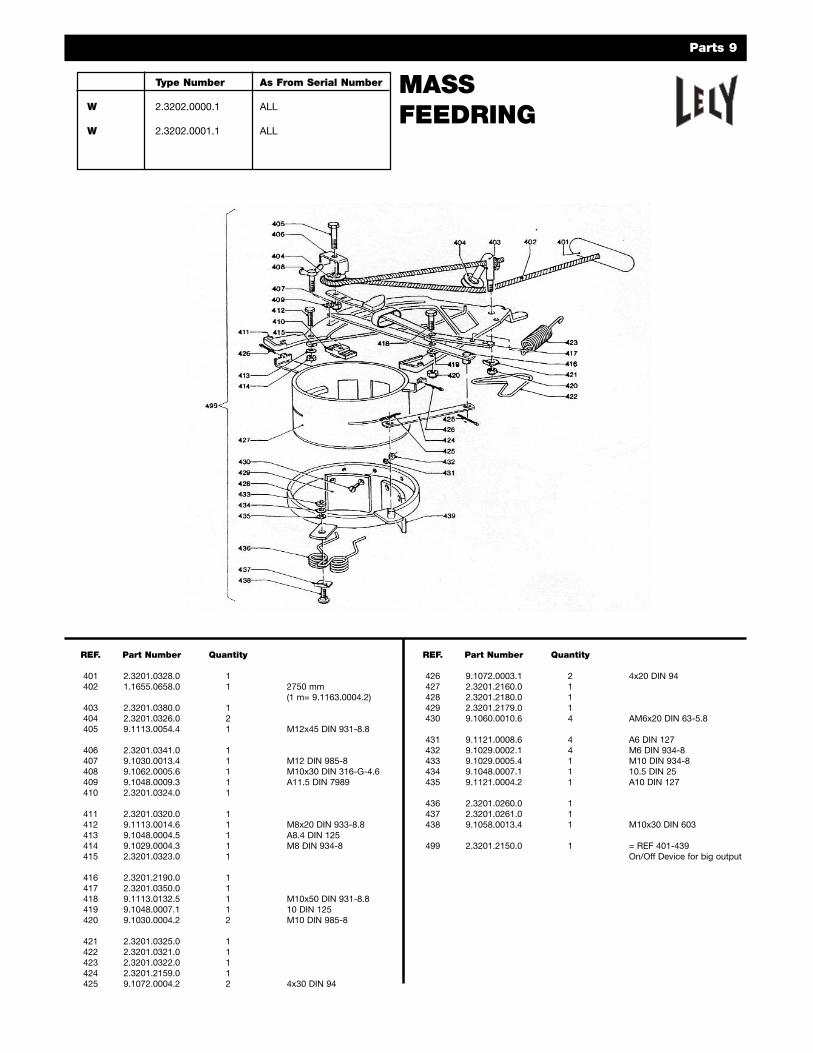
For the application of large quantities per acre, a Mass feedringassembly is available. For sand/salt applications it can be fittedthis feedring and sand/salt ejector disc featuring short spoons.When fitted with these attachments, the machine can spreadsand and/or salt on snow or frost covered parking lots, sidewalksor roads.
Mesh Grid ScreensScreens are available for all WFR & WGR spreaders. The screenprohibits solid masses of material from entering the feedring area.Blockage of the feedring assembly or an irregular flow offertilizer is avoided.
AgitatorsIn the spreader models H and L1250, an agitator can be fittedon the bottom disc to promote the flow of powdery fertilizer. Alsouse for the application of slags, lime or sand. Never use an agitator with granular fertilizer.
27
CONDENSED OPERATING INSTRUCTIONS** STANDARD FEEDRING**
FOR COMPLETE INFORMATION SEE YOUR OPERATORS MANUAL
• CHECK OIL LEVEL IN GEARBOX (SAE 90)• POSITION MACHINE AT CORRECT HEIGHT BEFORE
COUPLING P.T.O. SHAFT (EJECTOR DISC ± 20 INCHES OR 50 CM ABOVE GROUND)
INSTRUCCIONES DE FUNCIONAMIENTO RESUMIDAS**ALIMENTACIÓN NORMAL**
EL MANUAL DEL USUARIO CONTIENE LA INFORMACIÓN COMPLETA.
• REVISE EL NIVEL DE ACEITE EN LA CAJA DE ENGRANAJES (SAE90)
• COLOQUE LA MÁQUINA A LA ALTURA CORRECTA ANTES DE ACOPLAR EL EJE DE TOMA DE POTENCIA (DISCO EYECTOR ± 50 cm o 20 pulg. SOBRE EL SUELO)
BASIC CALIBRATION(Central spreading) LBS/Acre
Spreading width = 52 ft.Working Width = 40 ft.
CALIBRACIÓN BÁSICA(Distribución central) libras/acreAncho de distribución = 16 m
Ancho de trabajo = 12 m
DANGER: Maximum PTO speed is 540 R.P.M. Operate in range between 425 & 540 R.P.M.PELIGRO: La máxima velocidad de la toma de potencia es 540 rpm. Haga funcionar el equipo entre 425 y 540 rpm
ForwardMPH Speed
Velocidad deavance
(millas/h)
3 5 9
70258506
45155303
2386169
369
Position ofcalibration
scale.
Posición dela escala decalibración
Granulars (Large)Granulares (grandes)
Coarse (Gruesos)
Position Feedring 10 – 15Coloque el anillo de ali-mentación en 10 – 15
Quantity in lbs/acreCantidad en libras/acre
3 5 9
100423735
60254441
33141245
Granulars (Small)Granulares (pequeños)
Fine (Finos)
Position Feedring 10 – 15Coloque el anillo de
alimentación en 10 – 15Quantity in lbs/acre
3 5 9
45178464
27107280
1559155
Potash non-granularPotasa no granular
Spread = 26’, Work = 20’Position Feedring 7 – 9
Quantity in lbs/acre
3 5 9
187482857
112289514
62161286
Lime and slagsCal y escorias
Spread = 21’, Work = 16’Position Feedring 4 – 6
Quantity in lbs/acre
NOTE:1. USE THE AGITATOR FOR WET AND LUMPY MATERIALS ONLY. MIX SLAGS WITH SOME
WATER PRIOR TO SPREADING.2. THE SECTIONS I-V HAVE 3 ADJUSTMENT HOLES EACH IN ORDER TO OBTAIN A SPREADING
PATTERN AS REGULAR AS POSSIBLE OR CENTRAL.3. QUANTITIES LISTED ARE APPROXIMATE. EFFECTIVE OUTPUT MAY DIFFER.4. FOR COMPLETE INFORMATION SEE YOUR OPERATORS MANUAL.
NOTA:1. UTILICE EL AGITADOR ÚNICAMENTE PARA MATERIALES MOJADOS Y GRUMOSOS.
MEZCLE LAS ESCORIAS CON ALGO DE AGUA ANTES DE ESPARCIRLAS.2. LAS SECCIONES I-V TIENEN CADA UNA 3 ORIFICIOS DE AJUSTE A FIN DE LOGRAR UN
PATRÓN DE DISTRIBUCIÓN TAN REGULAR O CENTRAL COMO SEA POSIBLE.3. LAS CANTIDADES QUE APARECEN SON APROXIMADAS. LA SALIDA REAL PODRÍA
SER DIFERENTE.4. EL MANUAL DEL USUARIO CONTIENE LA INFORMACIÓN COMPLETA.
CAUTION: STOP THE PTO AND EJECTOR DISC BEFORE LEAVINGTHE TRACTOR OR VEHICLE TO CHANGE ANY SETTINGS OR FILLING THE SPREADER. KEEP CLEAR OF MOVING PARTS.
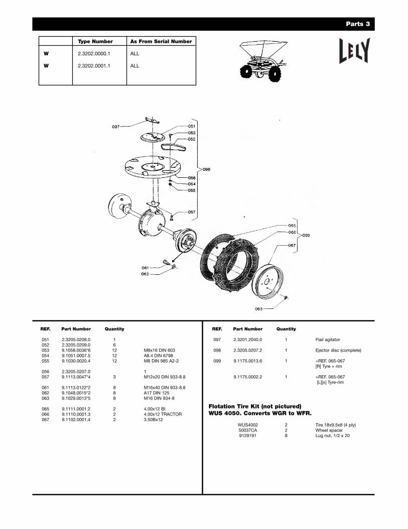
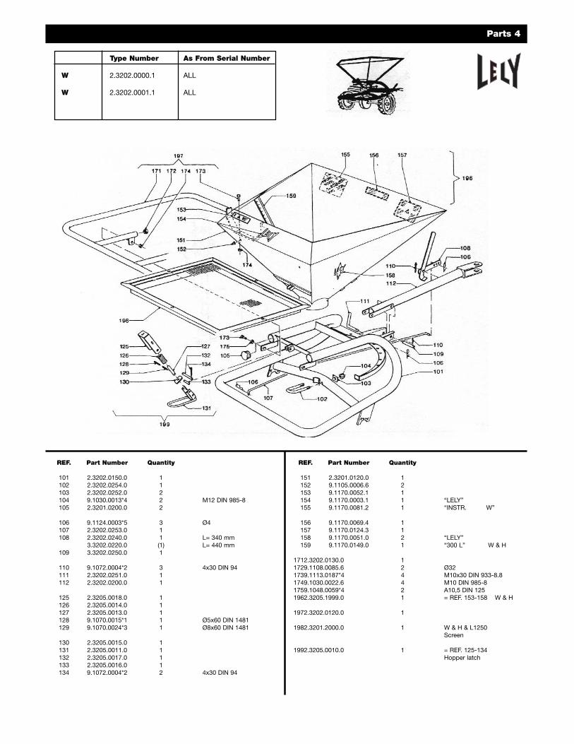
156 9.1170.0069.4 1157 9.1170.0124.3 1158 9.1170.0051.0 2 “LELY”159 9.1170.0149.0 1 “300 L” W & H
1712.3202.0130.0 11729.1108.0085.6 2 Ø321739.1113.0187*4 4 M10x30 DIN 933-8.81749.1030.0022.6 4 M10 DIN 985-81759.1048.0059*4 2 A10,5 DIN 1251962.3205.1999.0 1 = REF. 153-158 W & H