66
Landmarks Preservation CommissionSubmission June 9, 2011 Volume 1 LENOX HILL HOSPITAL - CENTER FOR COMPREHENSIVE CARE
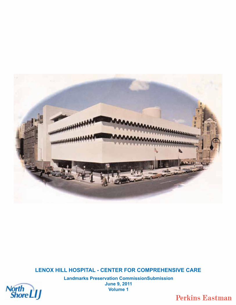
Landmarks Preservation CommissionSubmissionJune 9, 2011
Volume 1
LENOX HILL HOSPITAL - CENTER FOR COMPREHENSIVE CARE

2
3

4
5

6
Perkins Eastman
7
Perkins Eastman
8
Perkins Eastman
1 ’
9

10
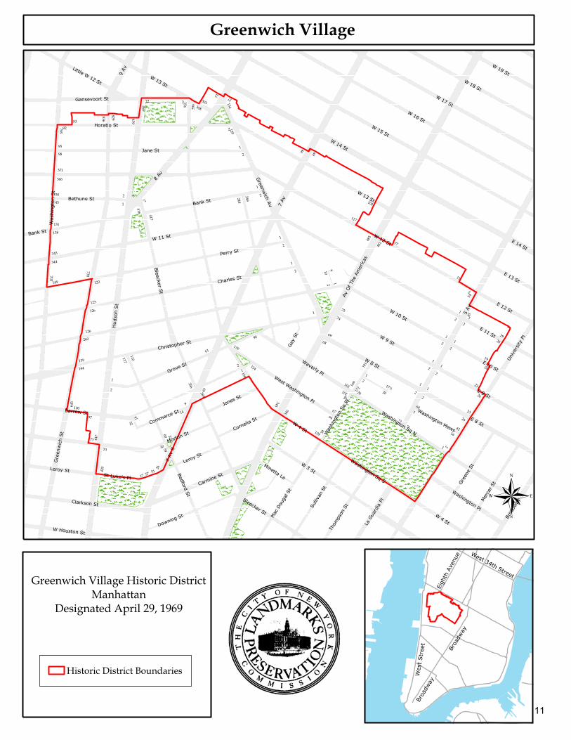
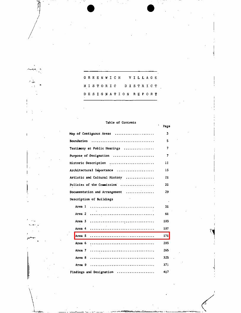
Greenwich Village
Wes
tStr
eet
West 34th Street
Broa
dway
Eigh
thAv
enue
Broa
dway
5Av
W 12 StW 11 St
W4 St
W 10 St
7Av
S
W 14 St
Hud
son
St
8Av
7Av
W 15 St
W 13 St
W 16 St
Gre
enw
ich
St
Perry St
Was
hing
ton
St
Jane St
AvOf T
heAm
ericas
Charles St
W3 St
W 17 St
Barrow St
Christopher St
Waverly Pl
E 8 St
Horatio St
Grove St
Morton St
Bedford St
Greenw
ichAv
E 9 St
W 18 St
W 9 St
W 8 St
Bank St
E 10 St
Univ
ersity
Pl
9Av
Mer
cer S
t
Gansevoort St
E 11 St
Clarkson St
Leroy St
Carmine St
Bethune St
Gree
neSt
W 19 St
Sulliva
nSt
E 12 St
Downing St
W Houston St
Mac
Doug
alSt
Broa
dway
Little W 12 St
Bleecker St
E 13 St
Jones St
Washington Sq S
Washington Sq N
West Washington Pl
Thom
pson
St
Washington Pl
Cornelia St
LaGu
ardi
aPl
Gay
St
Commerce St
E 14 St
Minetta LaSt Luke's Pl
Was
hing
ton
SqW
Washington Mews
W 13 St
BleeckerSt
Leroy St
W4 St
Bank St
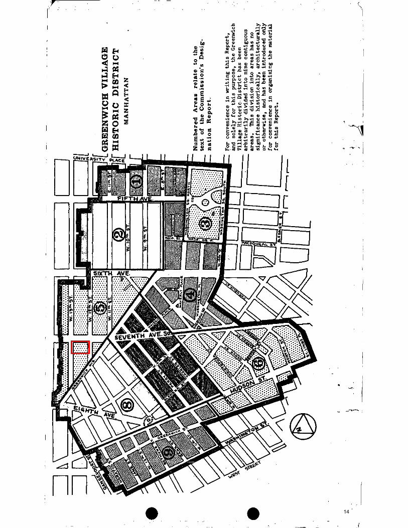
Greenwich Village Historic DistrictManhattan
Designated April 29, 1969
®
Historic District Boundaries
420
17 57 51
26
5930
27
60
14
9
28969
256
61139
98
70
73 447
97
100643
4152
1
2
117
110
139
144
260
1186
2 134
345
340
39129
64
102
39
67
28172
2
1
2
1
1642
26
23168
2
11
2
21
17½20
101 169
181
69
68
24
19
28
29
26
23
145
54
2
11
1
2
1
2
1
2
1
2
1
22
77
482
485
74
75
117
104
109
2 1
1
2
1
2
1
2
1
248
249
2
1 46
49
2129136
7273
303308
2356
3 56
650
22
639
8298 36
83
795
92
95
98
371
366
50 2
1
2
5
417
416
43
131
138
345
344
149 122
123
703
738
126
126
11
12
ORIGINAL DESIGNATION OF HISTORIC DISTRICT
13
14
15
16
17
18
Consulting Associates of NY, Inc Building Enclosure Experts
Monday, March 14 , 2011
Mr. Charles S. Maggio, AIA, NCARBSenior Vice President & National Director, Healthcare Practice Jones Lang LaSalle Americas, Inc. 601 Lexington AvenueNew York, NY 10022phone +212.812.5892 fax +312.470.3960
Subject: O’Toole Building (Joseph Curran National Maritime Union [NMU] Building) Re: Original Façade Surfacing and History
Dear Charles,
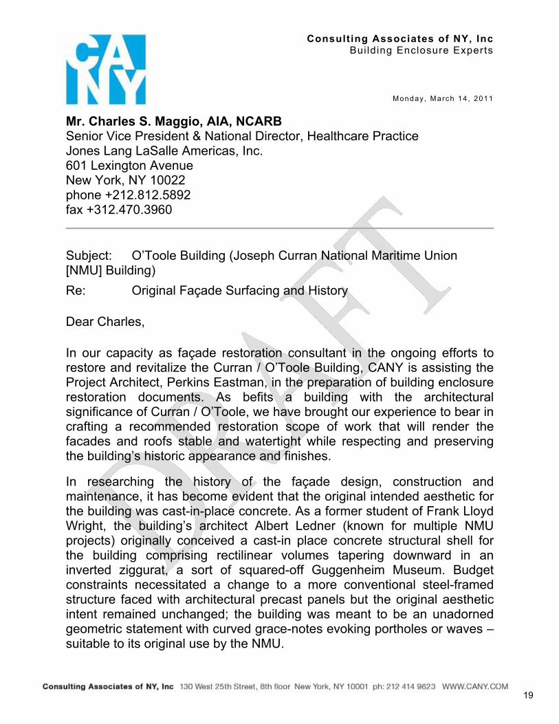
In our capacity as façade restoration consultant in the ongoing efforts to restore and revitalize the Curran / O’Toole Building, CANY is assisting the Project Architect, Perkins Eastman, in the preparation of building enclosure restoration documents. As befits a building with the architectural significance of Curran / O’Toole, we have brought our experience to bear in crafting a recommended restoration scope of work that will render the facades and roofs stable and watertight while respecting and preserving the building’s historic appearance and finishes.
In researching the history of the façade design, construction and maintenance, it has become evident that the original intended aesthetic for the building was cast-in-place concrete. As a former student of Frank Lloyd Wright, the building’s architect Albert Ledner (known for multiple NMU projects) originally conceived a cast-in place concrete structural shell for the building comprising rectilinear volumes tapering downward in an inverted ziggurat, a sort of squared-off Guggenheim Museum. Budget constraints necessitated a change to a more conventional steel-framed structure faced with architectural precast panels but the original aesthetic intent remained unchanged; the building was meant to be an unadorned geometric statement with curved grace-notes evoking portholes or waves – suitable to its original use by the NMU.
19
March 14, 2011 Curran / O’Toole: Original Facade Surfacing and History
Page 2 of 6
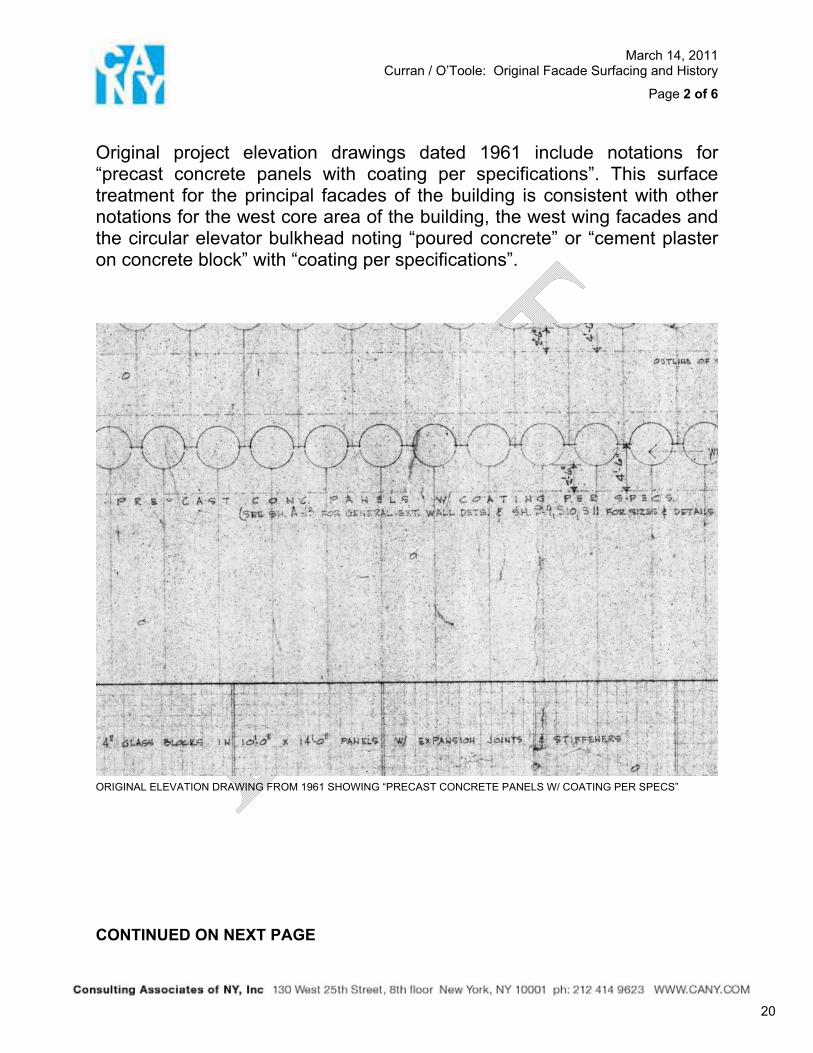
Original project elevation drawings dated 1961 include notations for “precast concrete panels with coating per specifications”. This surface treatment for the principal facades of the building is consistent with other notations for the west core area of the building, the west wing facades and the circular elevator bulkhead noting “poured concrete” or “cement plaster on concrete block” with “coating per specifications”.
ORIGINAL ELEVATION DRAWING FROM 1961 SHOWING “PRECAST CONCRETE PANELS W/ COATING PER SPECS”
CONTINUED ON NEXT PAGE
20
March 14, 2011 Curran / O’Toole: Original Facade Surfacing and History
Page 3 of 6
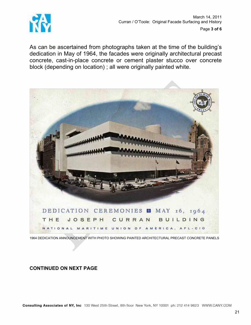
As can be ascertained from photographs taken at the time of the building’s dedication in May of 1964, the facades were originally architectural precast concrete, cast-in-place concrete or cement plaster stucco over concrete block (depending on location) ; all were originally painted white.
1964 DEDICATION ANNOUNCEMENT WITH PHOTO SHOWING PAINTED ARCHITECTURAL PRECAST CONCRETE PANELS
CONTINUED ON NEXT PAGE
21
March 14, 2011 Curran / O’Toole: Original Facade Surfacing and History
Page 4 of 6
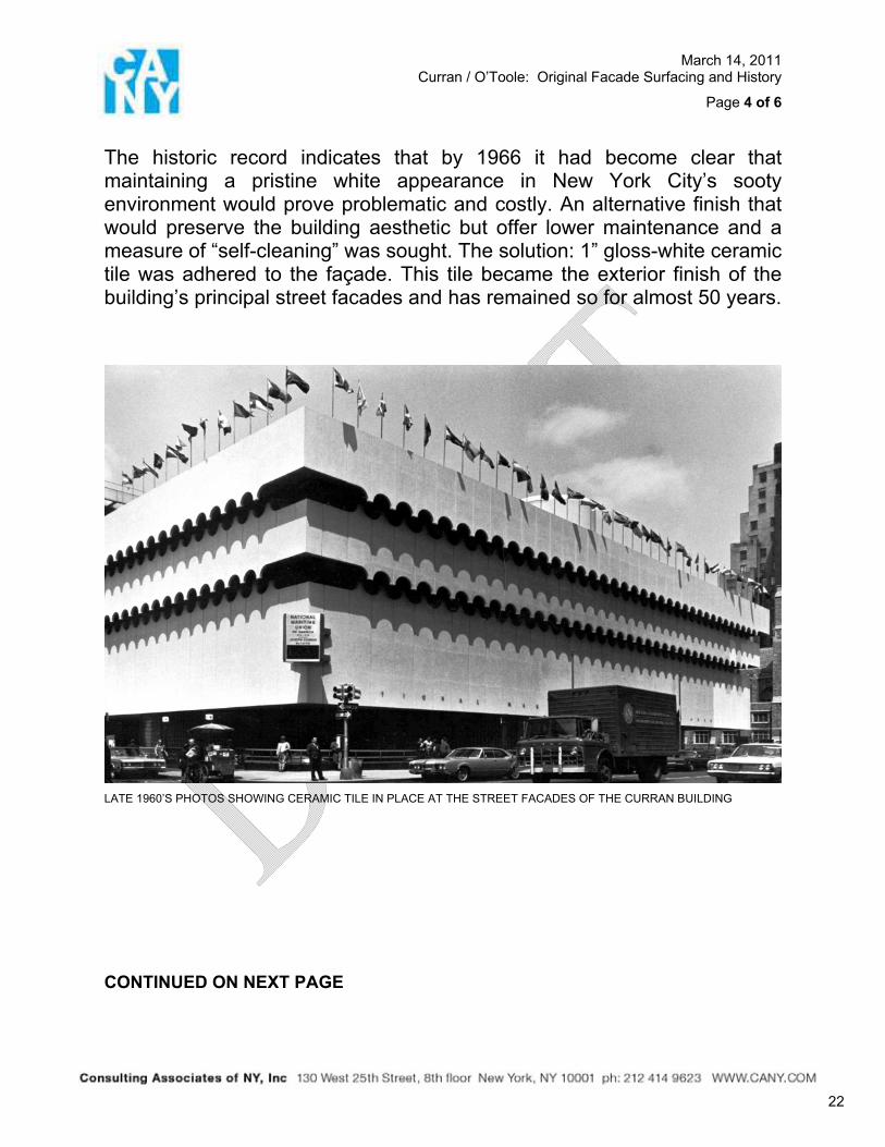
The historic record indicates that by 1966 it had become clear that maintaining a pristine white appearance in New York City’s sooty environment would prove problematic and costly. An alternative finish that would preserve the building aesthetic but offer lower maintenance and a measure of “self-cleaning” was sought. The solution: 1” gloss-white ceramic tile was adhered to the façade. This tile became the exterior finish of the building’s principal street facades and has remained so for almost 50 years.
LATE 1960’S PHOTOS SHOWING CERAMIC TILE IN PLACE AT THE STREET FACADES OF THE CURRAN BUILDING
CONTINUED ON NEXT PAGE
22
March 14, 2011 Curran / O’Toole: Original Facade Surfacing and History
Page 5 of 6
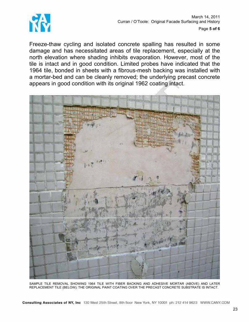
Freeze-thaw cycling and isolated concrete spalling has resulted in some damage and has necessitated areas of tile replacement, especially at the north elevation where shading inhibits evaporation. However, most of the tile is intact and in good condition. Limited probes have indicated that the 1964 tile, bonded in sheets with a fibrous-mesh backing was installed with a mortar-bed and can be cleanly removed; the underlying precast concrete appears in good condition with its original 1962 coating intact.
SAMPLE TILE REMOVAL SHOWING 1964 TILE WITH FIBER BACKING AND ADHESIVE MORTAR (ABOVE) AND LATER REPLACEMENT TILE (BELOW); THE ORIGINAL PAINT COATING OVER THE PRECAST CONCRETE SUBSTRATE IS INTACT.
23
March 14, 2011 Curran / O’Toole: Original Facade Surfacing and History
Page 6 of 6
I hope that this information is helpful in establishing the finish(es) appropriate to the renovation of this historically significant structure. Should you require further information, please do not hesitate to contact me.
Sincerely yours,
Jarrett Huddleston Executive Director
V:\Projects\971 - The O'Toole Building\A - Site Survey and Report of Findings\Let OToole_FacadeHist_03-14-11.doc
24
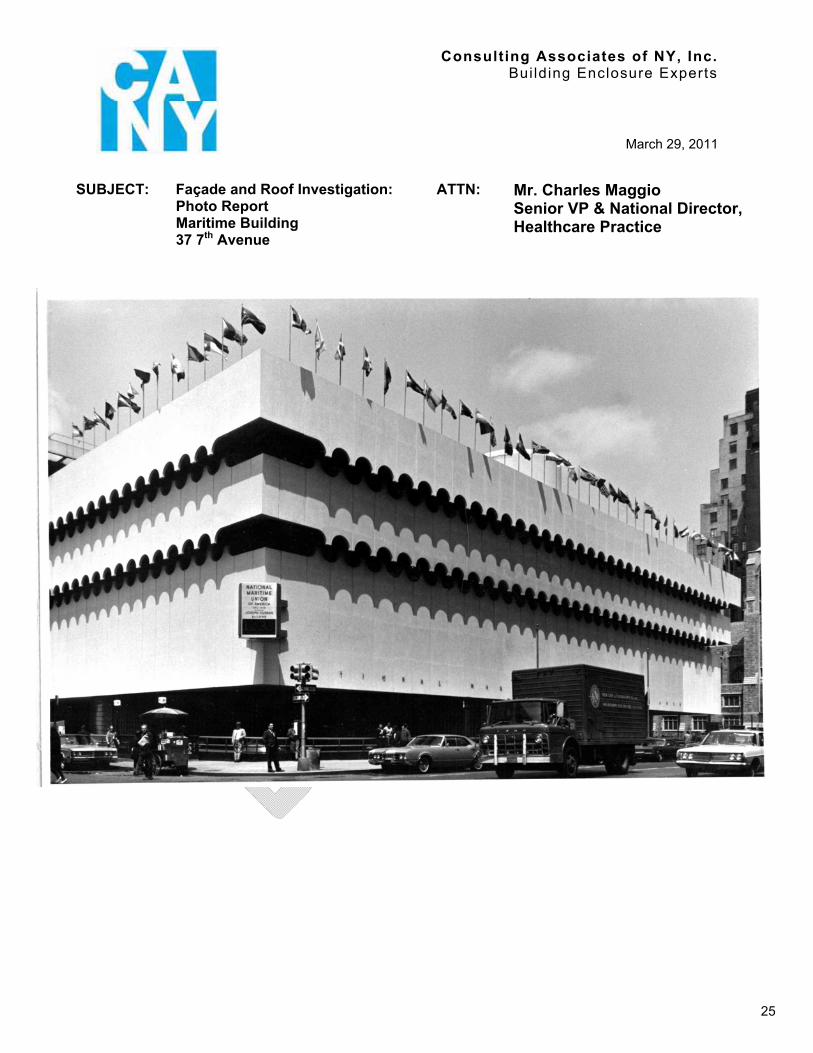
Consulting Associates of NY, Inc. Building Enclosure Experts
March 29, 2011
SUBJECT: Façade and Roof Investigation: Photo Report Maritime Building37 7th Avenue
ATTN: Mr. Charles Maggio Senior VP & National Director, Healthcare Practice
25
PART 1 - PHOTOGRAPHS
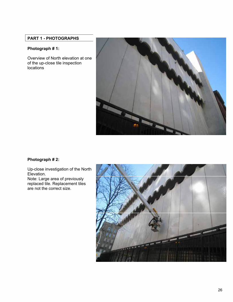
Photograph # 1:
Overview of North elevation at one of the up-close tile inspection locations
Photograph # 2:
Up-close investigation of the North Elevation.Note: Large area of previously replaced tile. Replacement tiles are not the correct size.
26
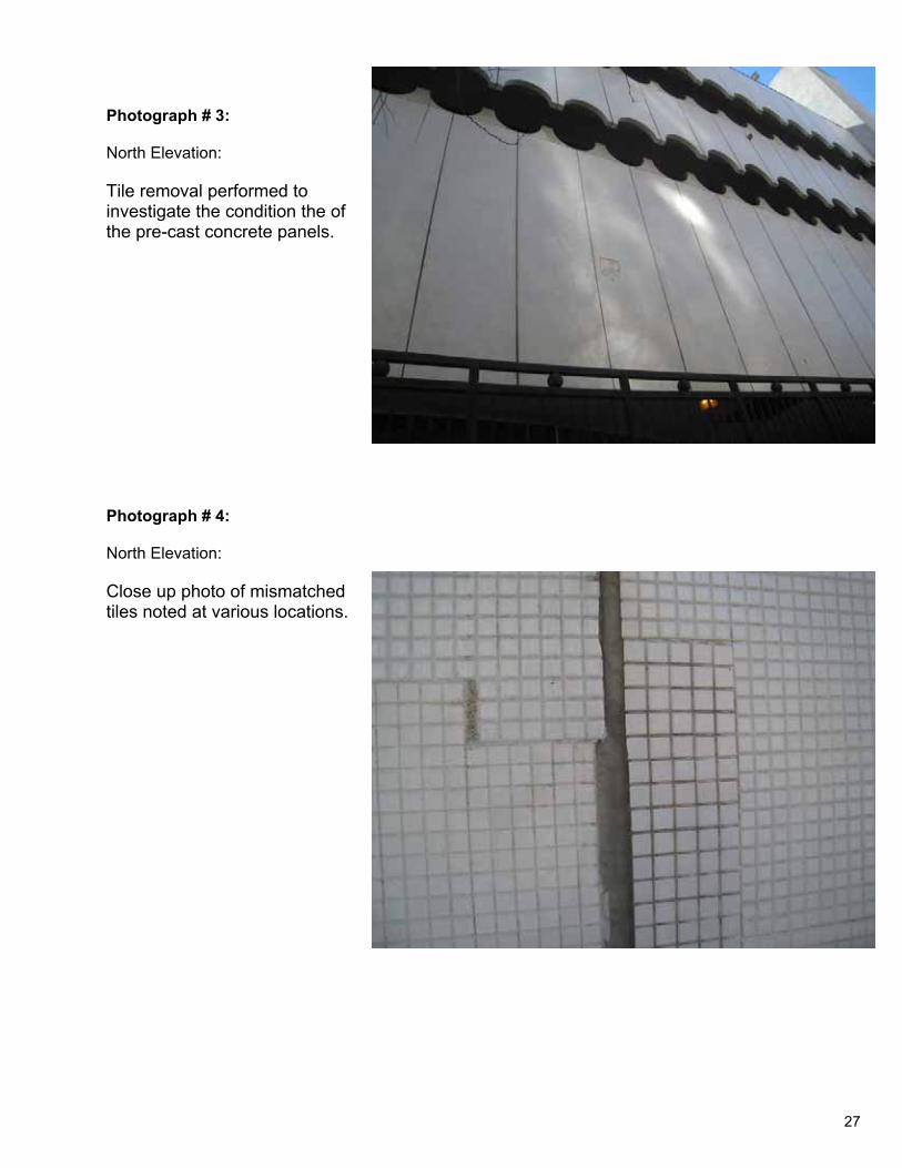
Photograph # 3:
North Elevation:
Tile removal performed to investigate the condition the of the pre-cast concrete panels.
Photograph # 4:
North Elevation:
Close up photo of mismatched tiles noted at various locations.
27
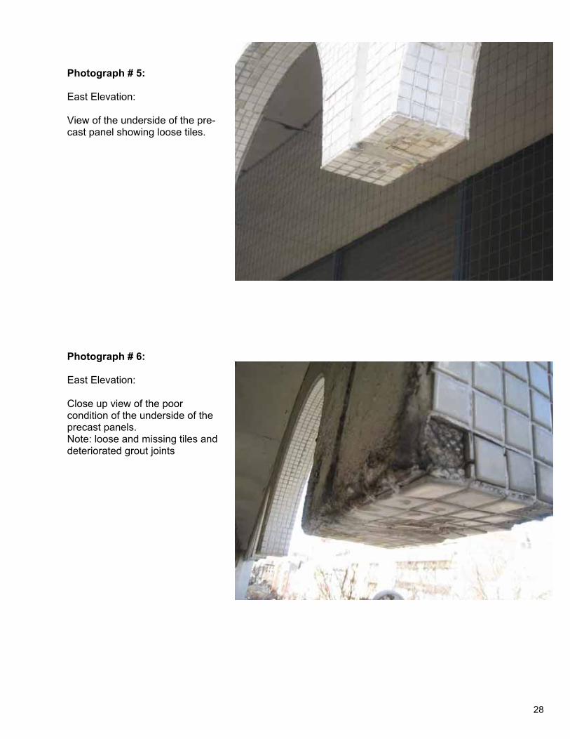
Photograph # 5:
East Elevation:
View of the underside of the pre-cast panel showing loose tiles.
Photograph # 6:
East Elevation:
Close up view of the poor condition of the underside of the precast panels. Note: loose and missing tiles and deteriorated grout joints
28
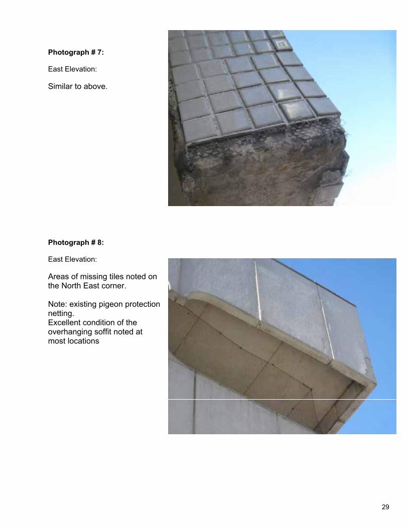
Photograph # 7:
East Elevation:
Similar to above.
Photograph # 8:
East Elevation:
Areas of missing tiles noted on the North East corner.
Note: existing pigeon protection netting.Excellent condition of the overhanging soffit noted at most locations
29
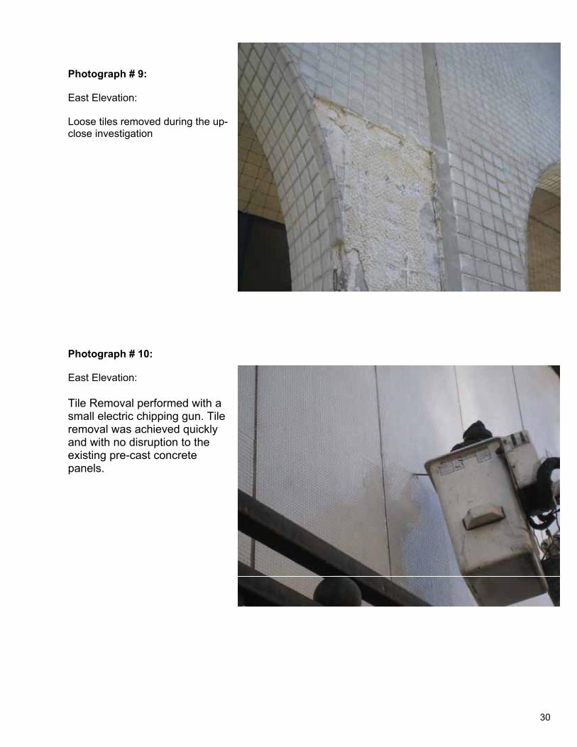
Photograph # 9:
East Elevation:
Loose tiles removed during the up-close investigation
Photograph # 10:
East Elevation:
Tile Removal performed with a small electric chipping gun. Tile removal was achieved quickly and with no disruption to the existing pre-cast concrete panels.
30
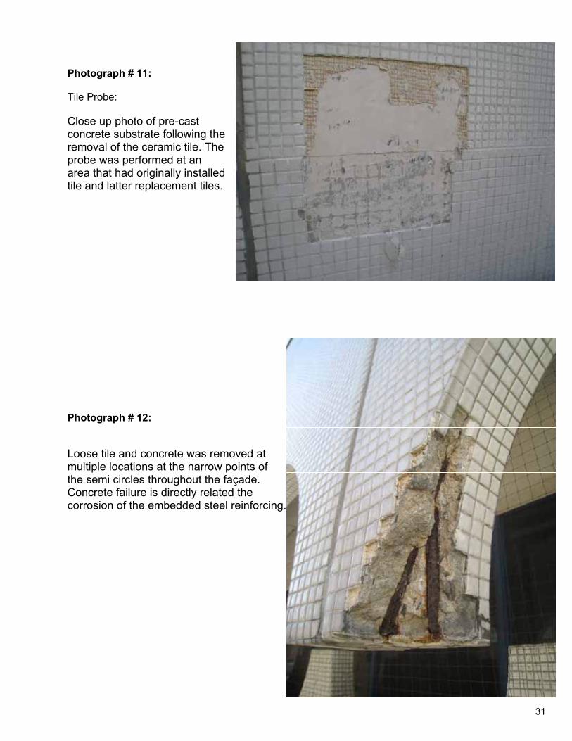
Photograph # 11:
Tile Probe:
Close up photo of pre-cast concrete substrate following the removal of the ceramic tile. The probe was performed at an area that had originally installed tile and latter replacement tiles.
Photograph # 12:
Loose tile and concrete was removed at multiple locations at the narrow points of the semi circles throughout the façade. Concrete failure is directly related the corrosion of the embedded steel reinforcing.
31
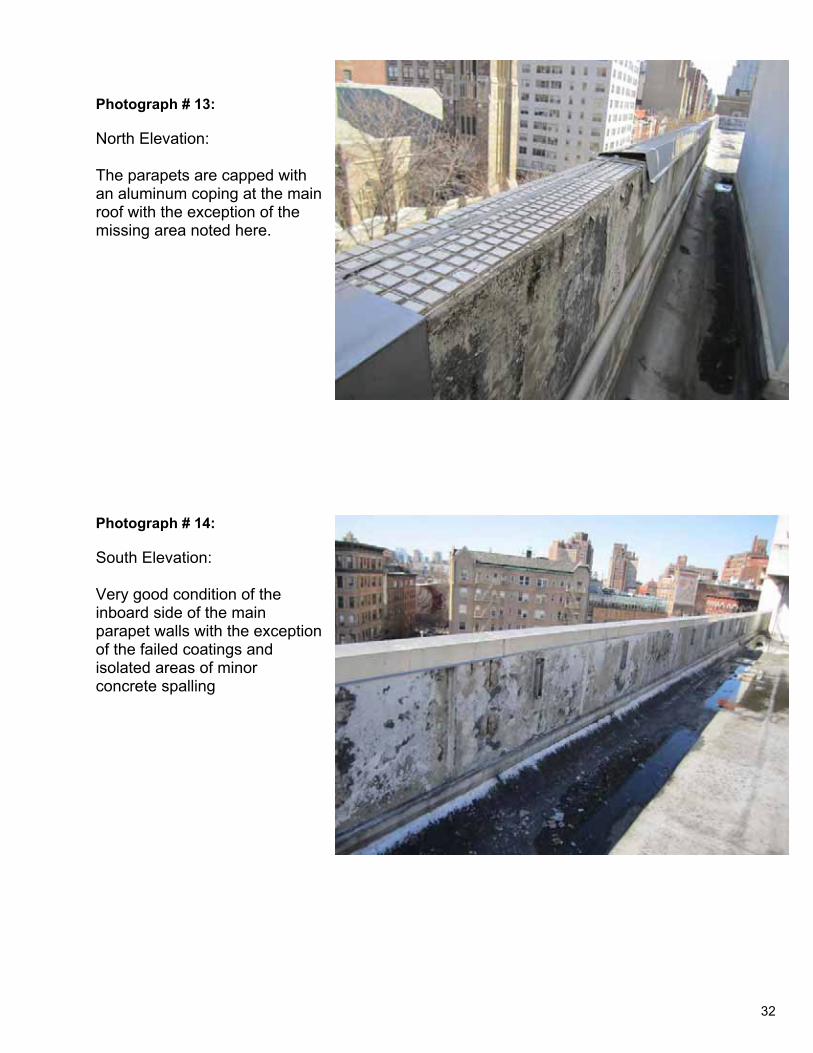
Photograph # 13:
North Elevation:
The parapets are capped with an aluminum coping at the main roof with the exception of the missing area noted here.
Photograph # 14:
South Elevation:
Very good condition of the inboard side of the main parapet walls with the exception of the failed coatings and isolated areas of minor concrete spalling
32
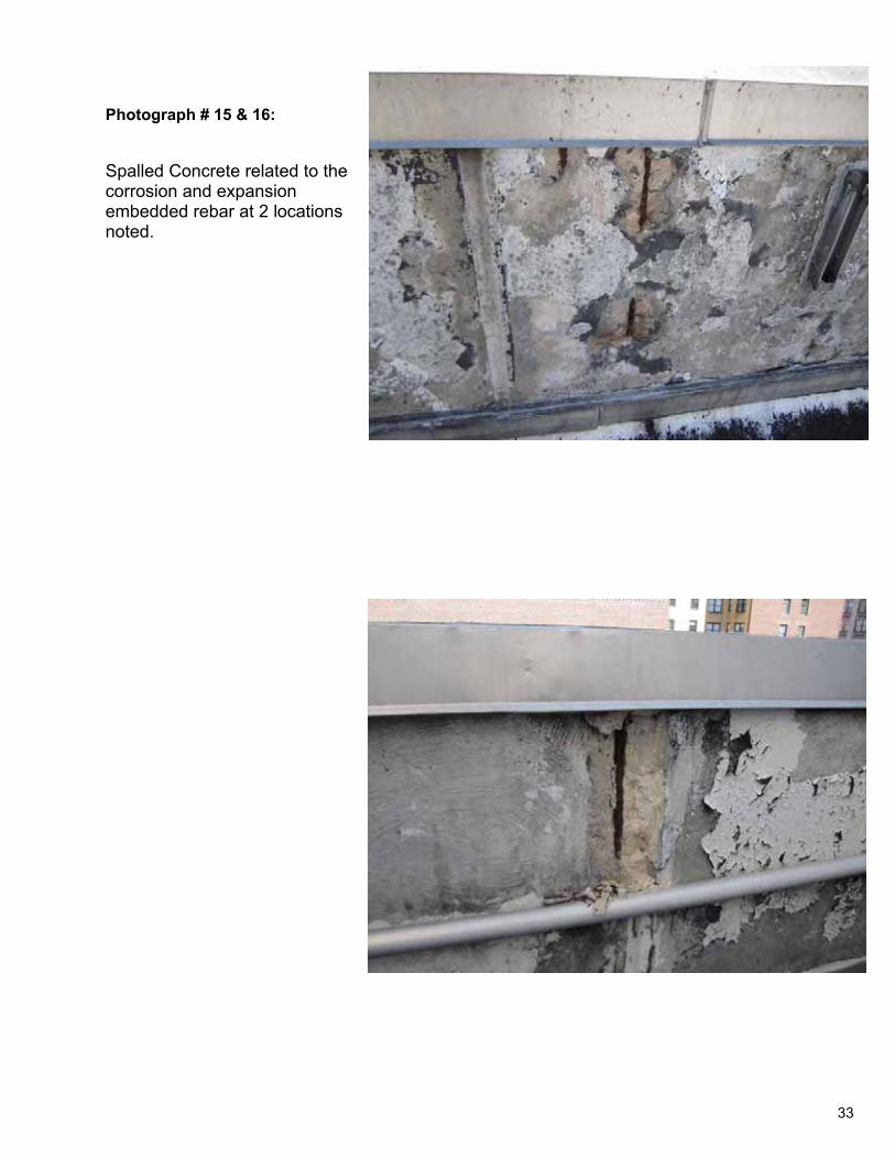
Photograph # 15 & 16:
Spalled Concrete related to the corrosion and expansion embedded rebar at 2 locations noted.
33
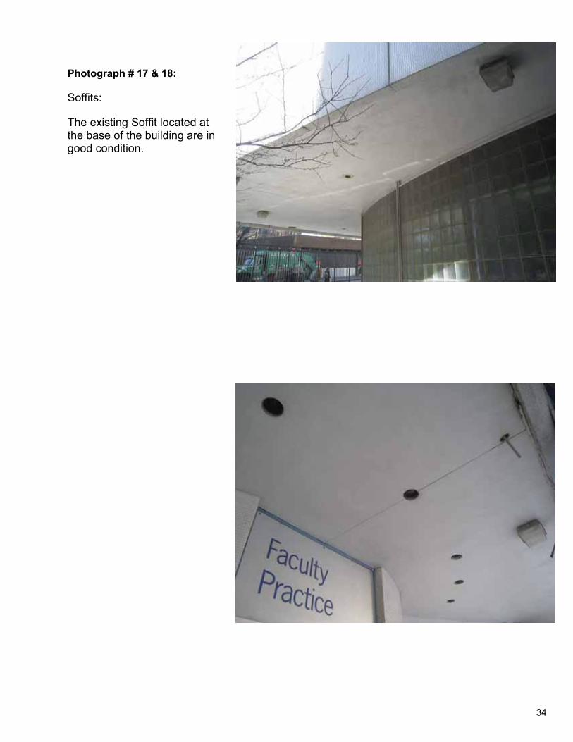
Photograph # 17 & 18:
Soffits:
The existing Soffit located at the base of the building are in good condition.
34
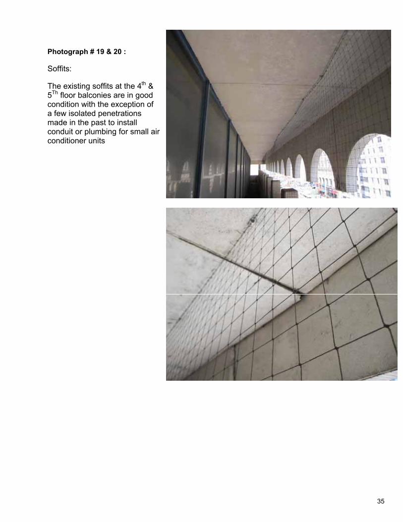
Photograph # 19 & 20 :
Soffits:
The existing soffits at the 4th & 5Th floor balconies are in good condition with the exception of a few isolated penetrations made in the past to install conduit or plumbing for small air conditioner units
35
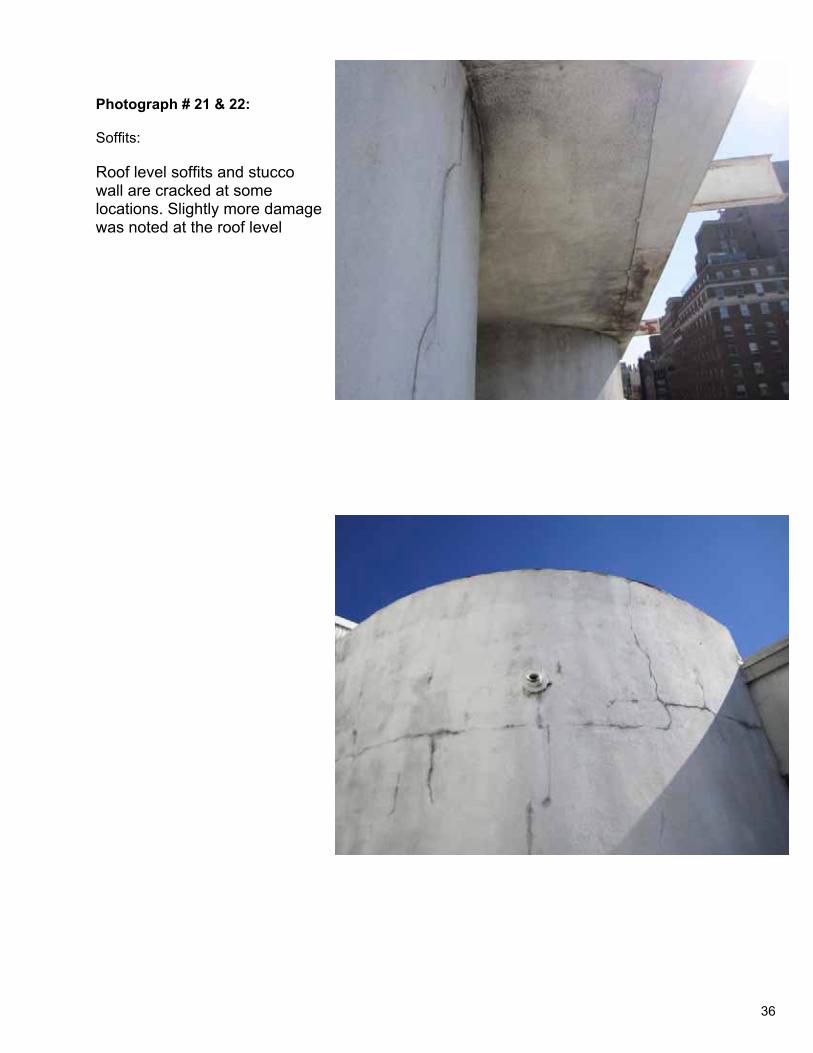
Photograph # 21 & 22:
Soffits:
Roof level soffits and stucco wall are cracked at some locations. Slightly more damage was noted at the roof level
36
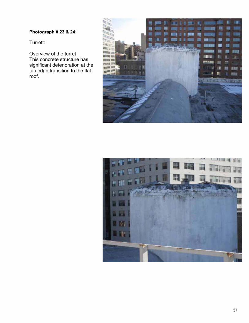
Photograph # 23 & 24:
Turrett:
Overview of the turret This concrete structure has significant deterioration at the top edge transition to the flat roof.
37
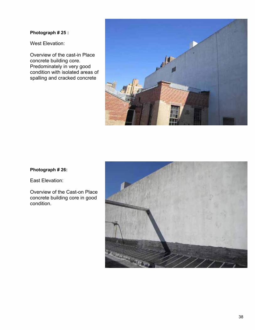
Photograph # 25 :
West Elevation:
Overview of the cast-in Place concrete building core. Predominately in very good condition with isolated areas of spalling and cracked concrete
Photograph # 26:
East Elevation:
Overview of the Cast-on Place concrete building core in good condition.
38
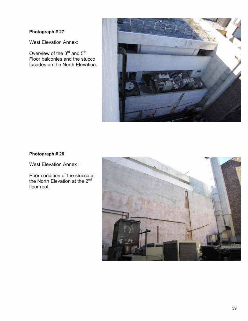
Photograph # 27:
West Elevation Annex:
Overview of the 3rd and 5th
Floor balconies and the stucco facades on the North Elevation.
Photograph # 28:
West Elevation Annex :
Poor condition of the stucco at the North Elevation at the 2nd
floor roof.
39
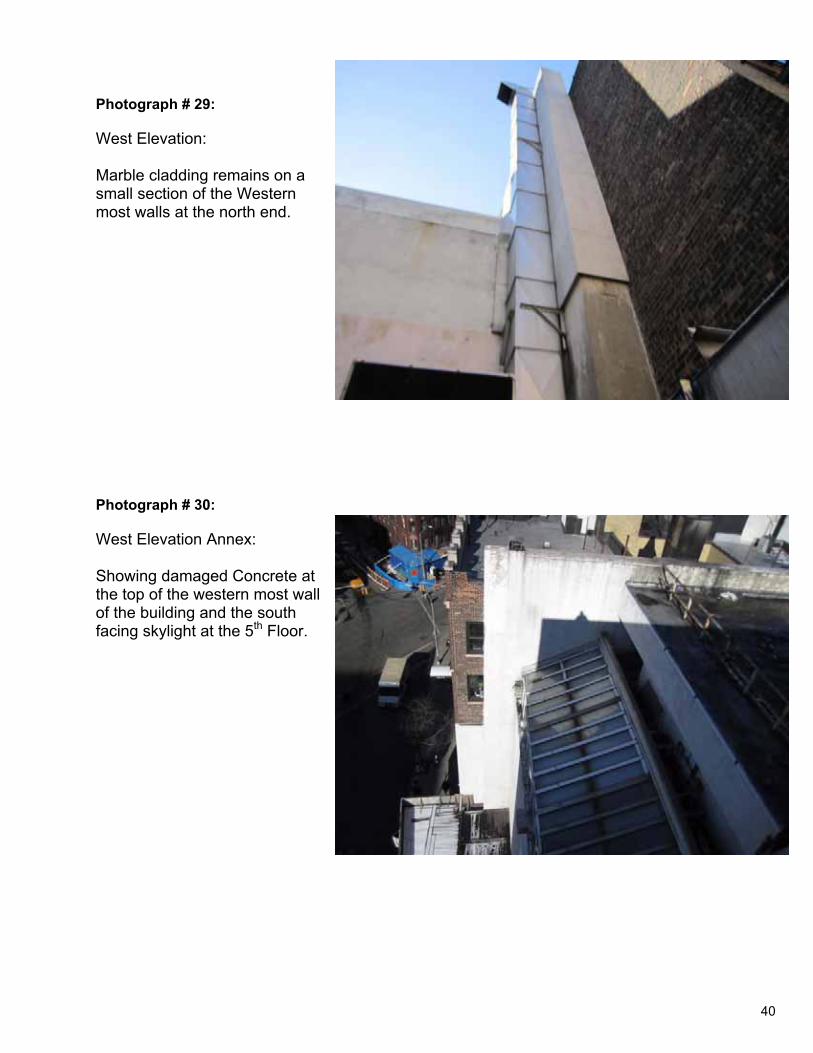
Photograph # 29:
West Elevation:
Marble cladding remains on a small section of the Western most walls at the north end.
Photograph # 30:
West Elevation Annex:
Showing damaged Concrete at the top of the western most wall of the building and the south facing skylight at the 5th Floor.
40
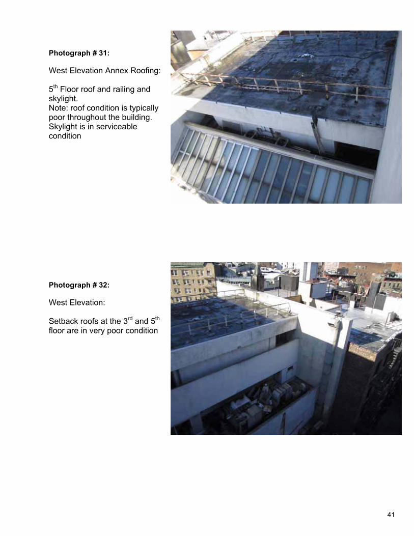
Photograph # 31:
West Elevation Annex Roofing:
5th Floor roof and railing and skylight.Note: roof condition is typically poor throughout the building. Skylight is in serviceable condition
Photograph # 32:
West Elevation:
Setback roofs at the 3rd and 5th
floor are in very poor condition
41
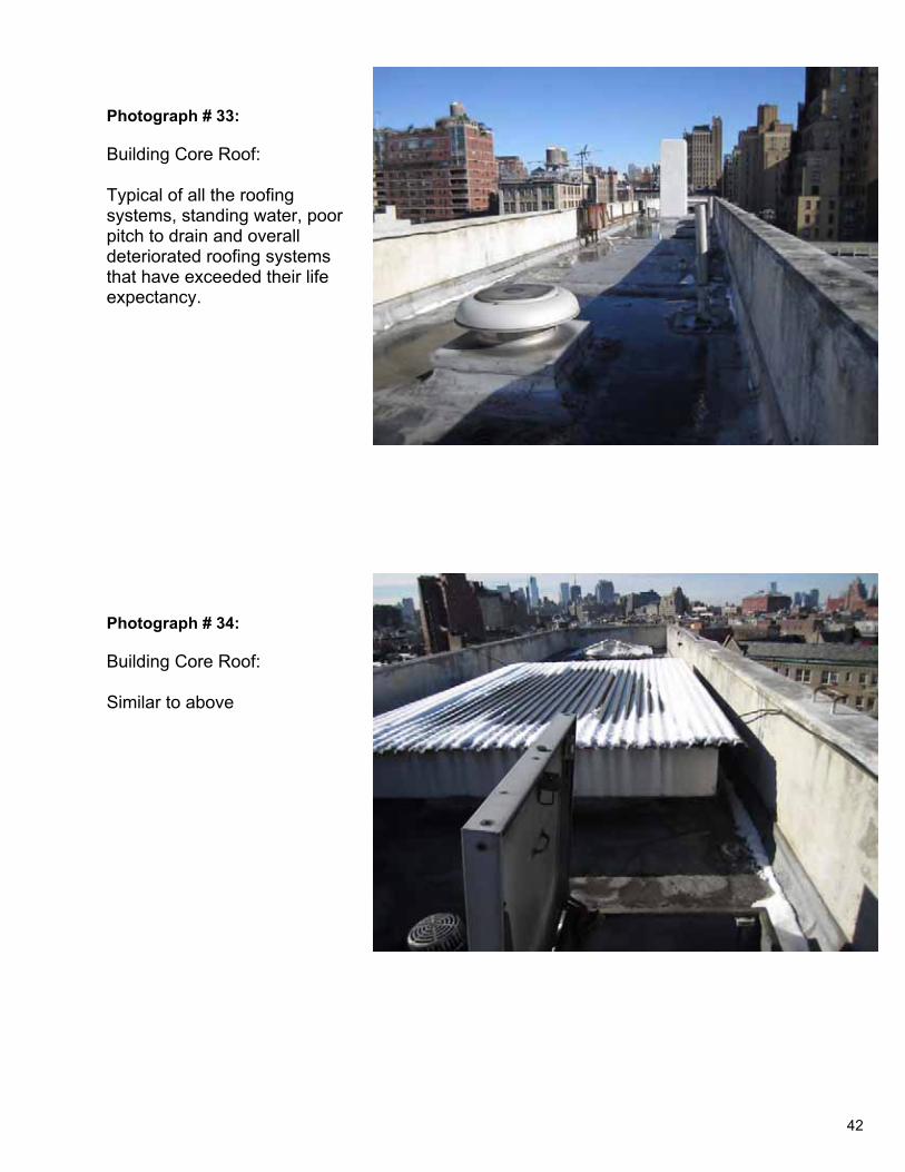
Photograph # 33:
Building Core Roof:
Typical of all the roofing systems, standing water, poor pitch to drain and overall deteriorated roofing systems that have exceeded their life expectancy.
Photograph # 34:
Building Core Roof:
Similar to above
42
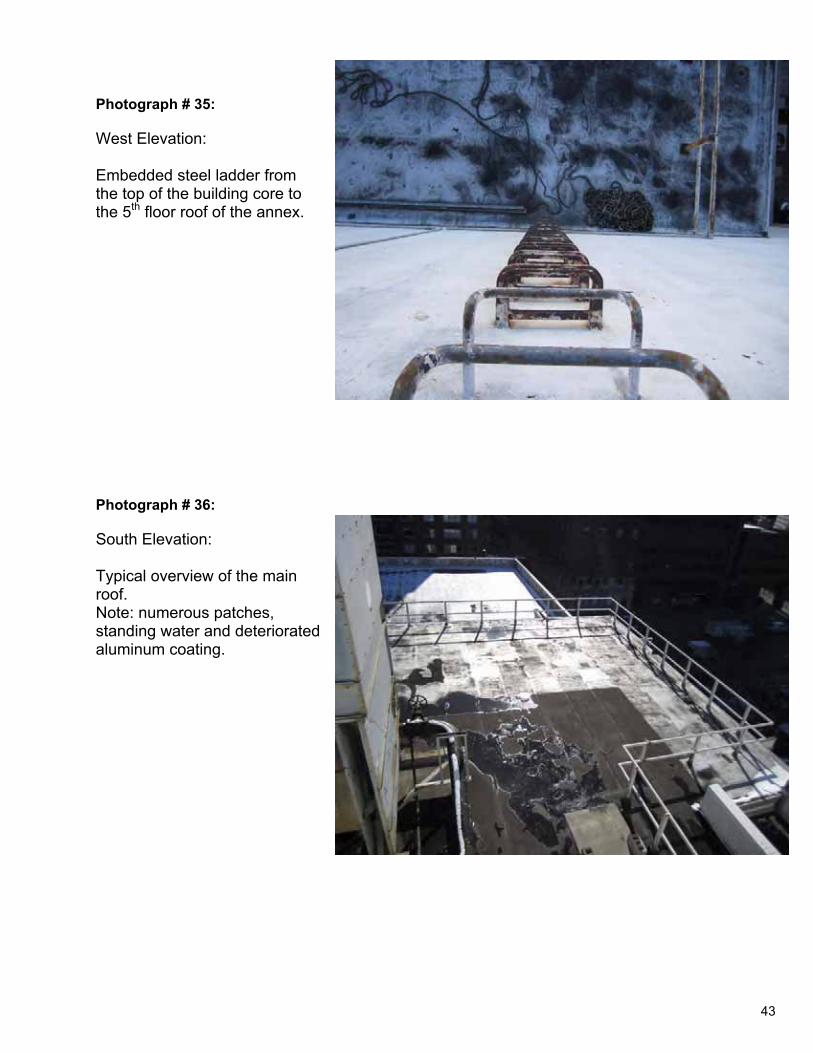
Photograph # 35:
West Elevation:
Embedded steel ladder from the top of the building core to the 5th floor roof of the annex.
Photograph # 36:
South Elevation:
Typical overview of the main roof.Note: numerous patches, standing water and deteriorated aluminum coating.
43
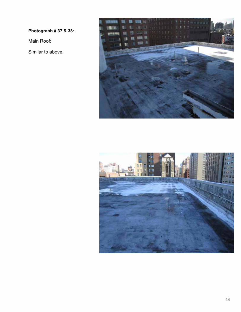
Photograph # 37 & 38:
Main Roof:
Similar to above.
44
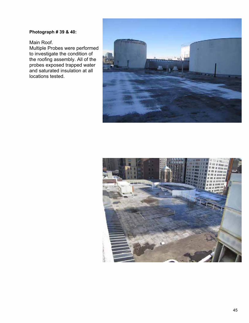
Photograph # 39 & 40:
Main Roof. Multiple Probes were performed to investigate the condition of the roofing assembly. All of the probes exposed trapped water and saturated insulation at all locations tested.
45
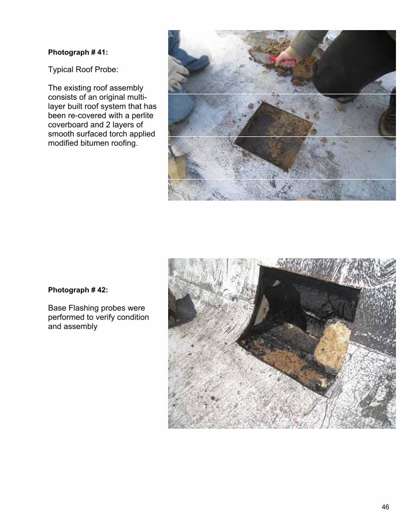
Photograph # 41:
Typical Roof Probe:
The existing roof assembly consists of an original multi-layer built roof system that has been re-covered with a perlite coverboard and 2 layers of smooth surfaced torch applied modified bitumen roofing.
Photograph # 42:
Base Flashing probes were performed to verify condition and assembly
46

Photograph # 43:
Roof Probes:
The average depth of the roof system is 2.5 – 3 inches.
Photograph # 44:
Roof Probes:
Typical base flashing probe, exposed the embedded steel clips that support the façade panels along the perimeter of the roof.
47
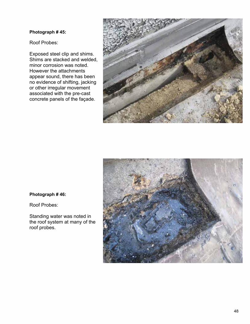
Photograph # 45:
Roof Probes:
Exposed steel clip and shims. Shims are stacked and welded, minor corrosion was noted. However the attachments appear sound, there has been no evidence of shifting, jacking or other irregular movement associated with the pre-cast concrete panels of the façade.
Photograph # 46:
Roof Probes:
Standing water was noted in the roof system at many of the roof probes.
48
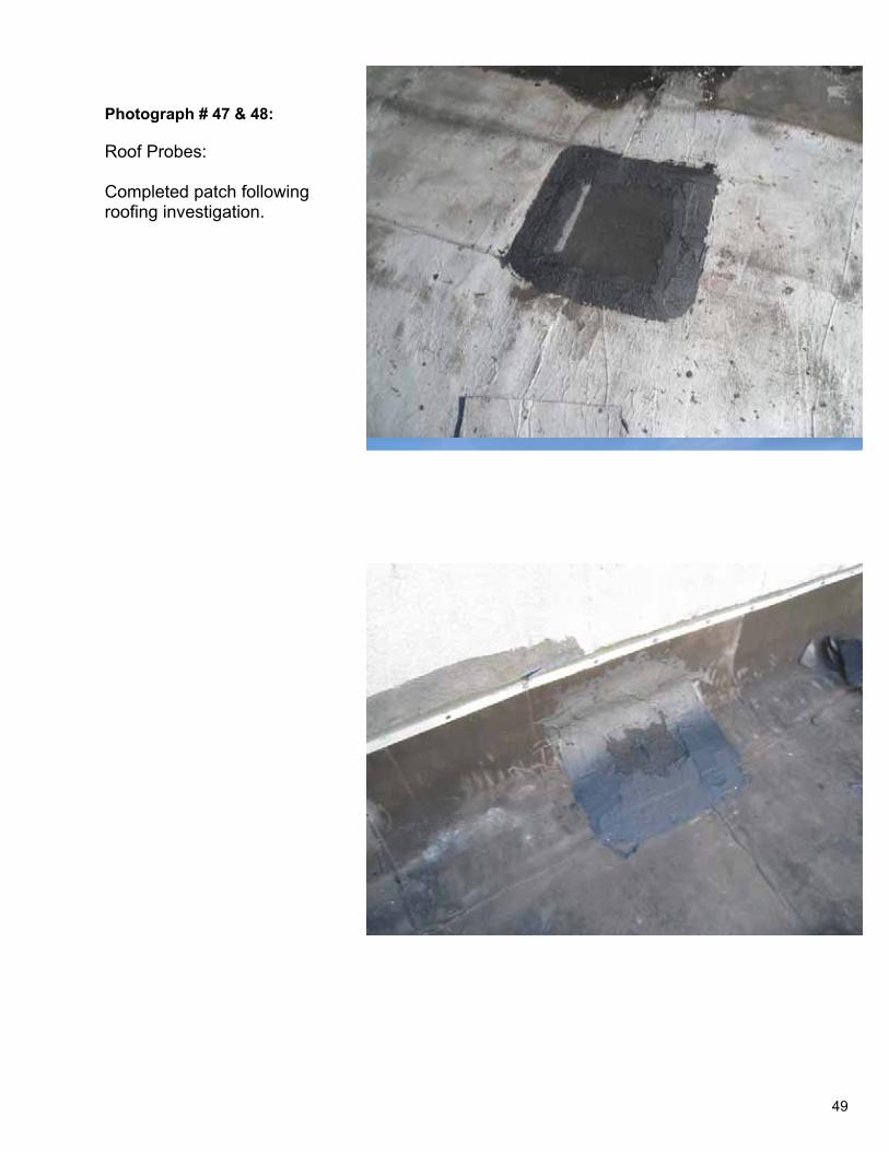
Photograph # 47 & 48:
Roof Probes:
Completed patch following roofing investigation.
49
Consult ing Associates of NY, Inc Bui ld ing Enclosure Experts
Tuesday , June 6 th , 2011
Mr. Reinaldo Gutierrez, RA Senior Associate Perkins Eastman 115 Fifth Avenue New York, NY 10003 T. 212.353.7331 Subject: Fenestration
Dear Mr. Gutierrez,
Typical Fourth and Fifth Floor Windows
The existing window system at the fourth and fifth floors of the Maritime Building are located within the loggia overhang / setback at each level and are recessed 4’0” from the parapet and 5’0” from the face of the soffit overhang. Because of the continuous scalloped parapet and soffit at each level, approximately the upper 1/3 of the glazing is visible from the exterior at each level. The typical assembly comprises painted cold-rolled steel framing with applied, mechanically-attached, painted steel glazing beads at the interior. Glazing is monolithic. Vision lites are fixed; there are no operable lites. The typical assembly measures 8’6” in height with a 7’0” vision lite over an 18” painted steel panel at the base. Typical steel framing mullions measure approximately 2 ½” wide. Corners are butt-glazed with small stainless steel retention clips approximately 18” o.c. There are two painted steel-framed glass doors accessing each of the loggias at the west end of the north and south elevations.
The existing window assembly is thermally inefficient and in poor condition. The framing was assembled without incorporating a thermal break and external temperatures are transmitted directly to the interior due to the conductive nature of the steel framing. The monolithic glazing is similarly thermally inefficient providing little insulating value. Corrosion of the steel framing members and glazing beads is common, especially at the vision sill and base panel. Corrosion has resulted in some deformation of the steel framing components. The existing assembly should be replaced with a contemporary painted aluminum thermally broken assembly with insulated glass units. Framing would be painted with the appropriate historic paint color and would reproduce the appearance and sight-lines of the existing assembly. Doors and corner butt-glazing would similarly reproduce existing sight-lines and paint color (as applicable).
Glass Block
The first floor façade of the maritime building incorporates two curved segments of glass block wall running north and south from the building entrance on 7th Avenue and curving westward to enclose the principal interior space of the ground floor, originally the union halls. The glass block walls are set-back 10’0”-to-30’0” beneath the cantilevered
50
June 6, 2011
Page 2 of 2
overhang of the interstitial floor above. The typical glass block walls are approximately 10’ in height constructed from 12” glass blocks approximately 4” deep. Glass block is laid-up in mortar in 14’0” panels separated by painted vertical steel framing members. The panels are captured top and bottom by curved painted steel track framing.
The existing glass block assembly is in poor condition with a large number or previous replacement blocks, most mismatched. There are a large number of fracture units, both original and replacements and a significant number of block retaining water and mold growth. Conditions indicate ongoing corrosion of the steel framing members with the resulting rust expansion exerting ongoing pressure on the glass and fracturing the units. Proper repair requires complete demolition and rebuilding with glass block, channel glass or facetted storefront matching the dimensions of the 4th and 5th floor window framing assembly as determined appropriate by LPC.
Sincerely yours,
Thomas Seminara Vice President Technical Management
51
Consulting Associates of NY, Inc Building Enclosure Experts
Apr i l 14 , 2011
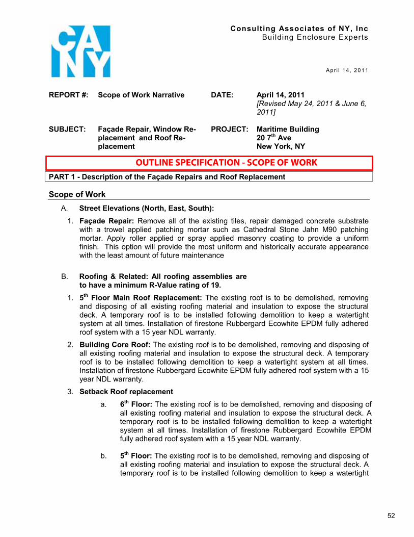
REPORT #: Scope of Work Narrative DATE: April 14, 2011[Revised May 24, 2011 & June 6, 2011]
SUBJECT: Façade Repair, Window Re-placement and Roof Re-placement
PROJECT: Maritime Building20 7th Ave New York, NY
PART 1 - Description of the Façade Repairs and Roof Replacement
Scope of Work
A. Street Elevations (North, East, South): 1. Façade Repair: Remove all of the existing tiles, repair damaged concrete substrate
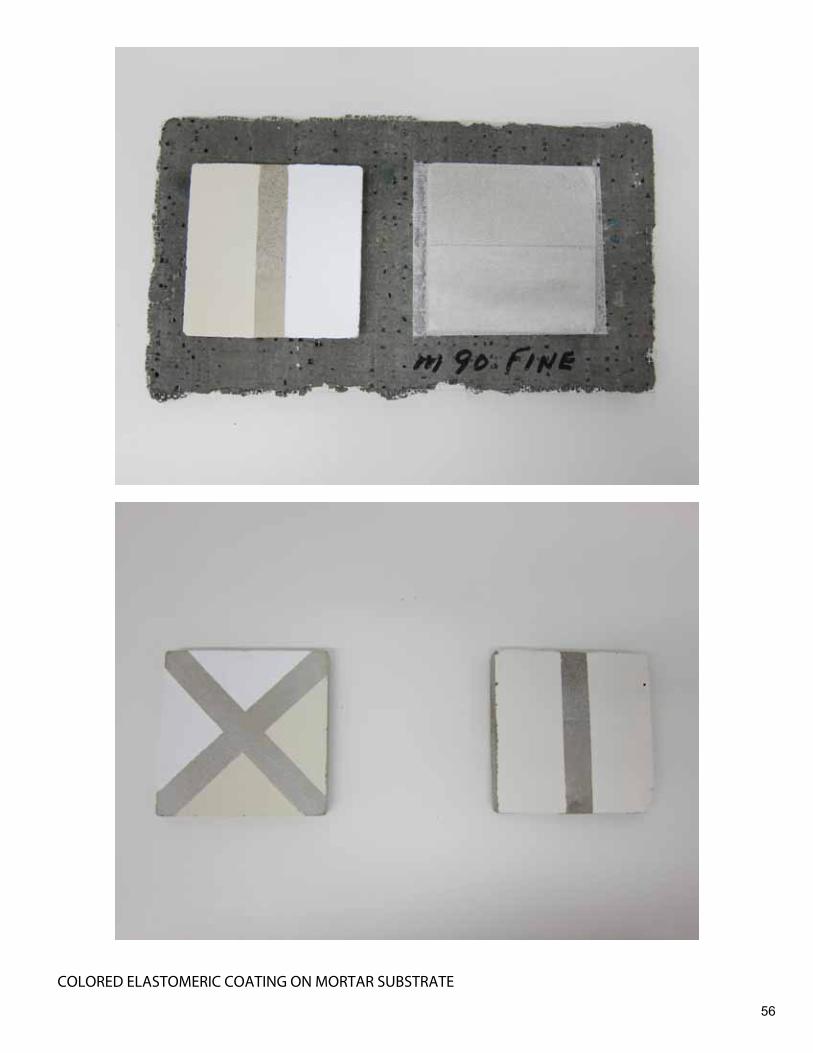
with a trowel applied patching mortar such as Cathedral Stone Jahn M90 patching mortar. Apply roller applied or spray applied masonry coating to provide a uniform finish. This option will provide the most uniform and historically accurate appearance with the least amount of future maintenance
B. Roofing & Related: All roofing assemblies are to have a minimum R-Value rating of 19.
1. 5th Floor Main Roof Replacement: The existing roof is to be demolished, removing and disposing of all existing roofing material and insulation to expose the structural deck. A temporary roof is to be installed following demolition to keep a watertight system at all times. Installation of firestone Rubbergard Ecowhite EPDM fully adhered roof system with a 15 year NDL warranty.
2. Building Core Roof: The existing roof is to be demolished, removing and disposing of all existing roofing material and insulation to expose the structural deck. A temporary roof is to be installed following demolition to keep a watertight system at all times. Installation of firestone Rubbergard Ecowhite EPDM fully adhered roof system with a 15 year NDL warranty.
3. Setback Roof replacement a. 6th Floor: The existing roof is to be demolished, removing and disposing of
all existing roofing material and insulation to expose the structural deck. A temporary roof is to be installed following demolition to keep a watertight system at all times. Installation of firestone Rubbergard Ecowhite EPDM fully adhered roof system with a 15 year NDL warranty.
b. 5th Floor: The existing roof is to be demolished, removing and disposing of all existing roofing material and insulation to expose the structural deck. A temporary roof is to be installed following demolition to keep a watertight
52
OUTLINE SPECIFICATION - SCOPE OF WORK
MARITIME BUILDING Scope of Work Narrative PAGE 2 OF 2 PREPARED BY CONSULTING ASSOCIATES OF NEW YORK 130 WEST 25TH STREET, 8TH FLOOR, NEW YORK, NY 10001
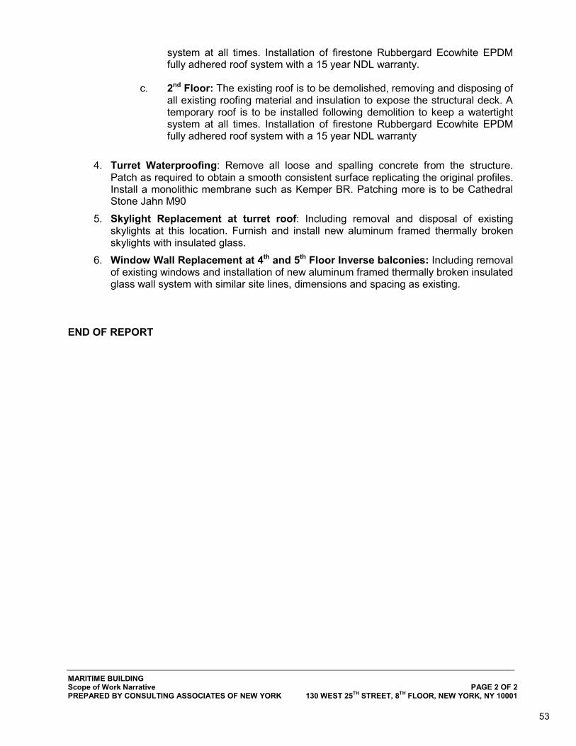
system at all times. Installation of firestone Rubbergard Ecowhite EPDM fully adhered roof system with a 15 year NDL warranty.
c. 2nd Floor: The existing roof is to be demolished, removing and disposing of
all existing roofing material and insulation to expose the structural deck. A temporary roof is to be installed following demolition to keep a watertight system at all times. Installation of firestone Rubbergard Ecowhite EPDM fully adhered roof system with a 15 year NDL warranty
4. Turret Waterproofing: Remove all loose and spalling concrete from the structure. Patch as required to obtain a smooth consistent surface replicating the original profiles. Install a monolithic membrane such as Kemper BR. Patching more is to be Cathedral Stone Jahn M90
5. Skylight Replacement at turret roof: Including removal and disposal of existing skylights at this location. Furnish and install new aluminum framed thermally broken skylights with insulated glass.
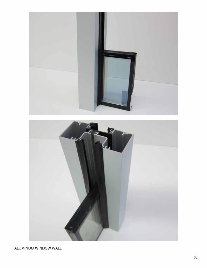
6. Window Wall Replacement at 4th and 5th Floor Inverse balconies: Including removal of existing windows and installation of new aluminum framed thermally broken insulated glass wall system with similar site lines, dimensions and spacing as existing.
END OF REPORT
53

54
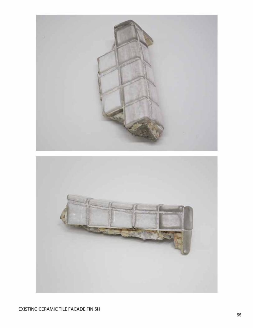
55EXISTING CERAMIC TILE FACADE FINISH
56
COLORED ELASTOMERIC COATING ON MORTAR SUBSTRATE
57
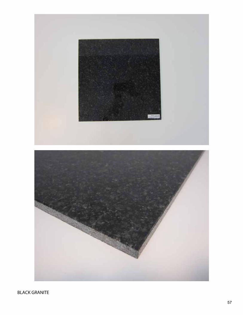
BLACK GRANITE
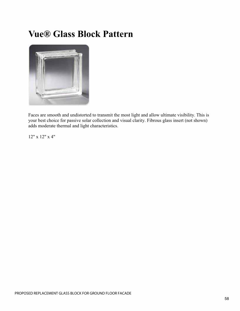
Vue® Glass Block Pattern
Faces are smooth and undistorted to transmit the most light and allow ultimate visibility. This is your best choice for passive solar collection and visual clarity. Fibrous glass insert (not shown) adds moderate thermal and light characteristics.
12" x 12" x 4"
58PROPOSED REPLACEMENT GLASS BLOCK FOR GROUND FLOOR FACADE
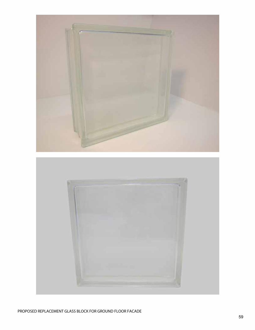
59PROPOSED REPLACEMENT GLASS BLOCK FOR GROUND FLOOR FACADE
60
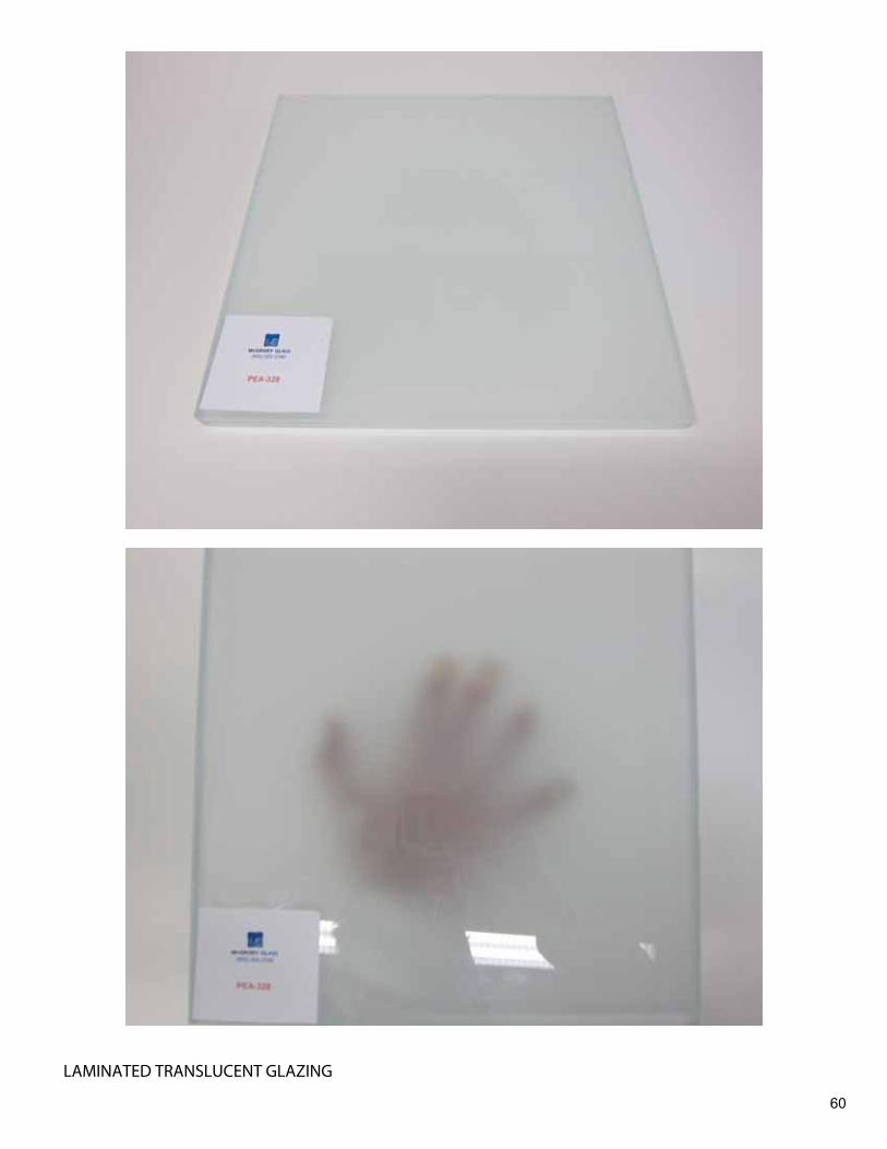
LAMINATED TRANSLUCENT GLAZING
61
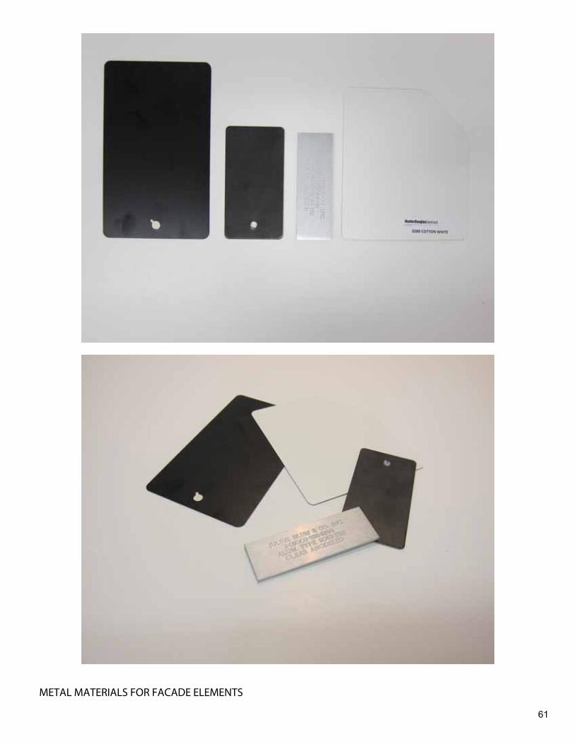
METAL MATERIALS FOR FACADE ELEMENTS
62
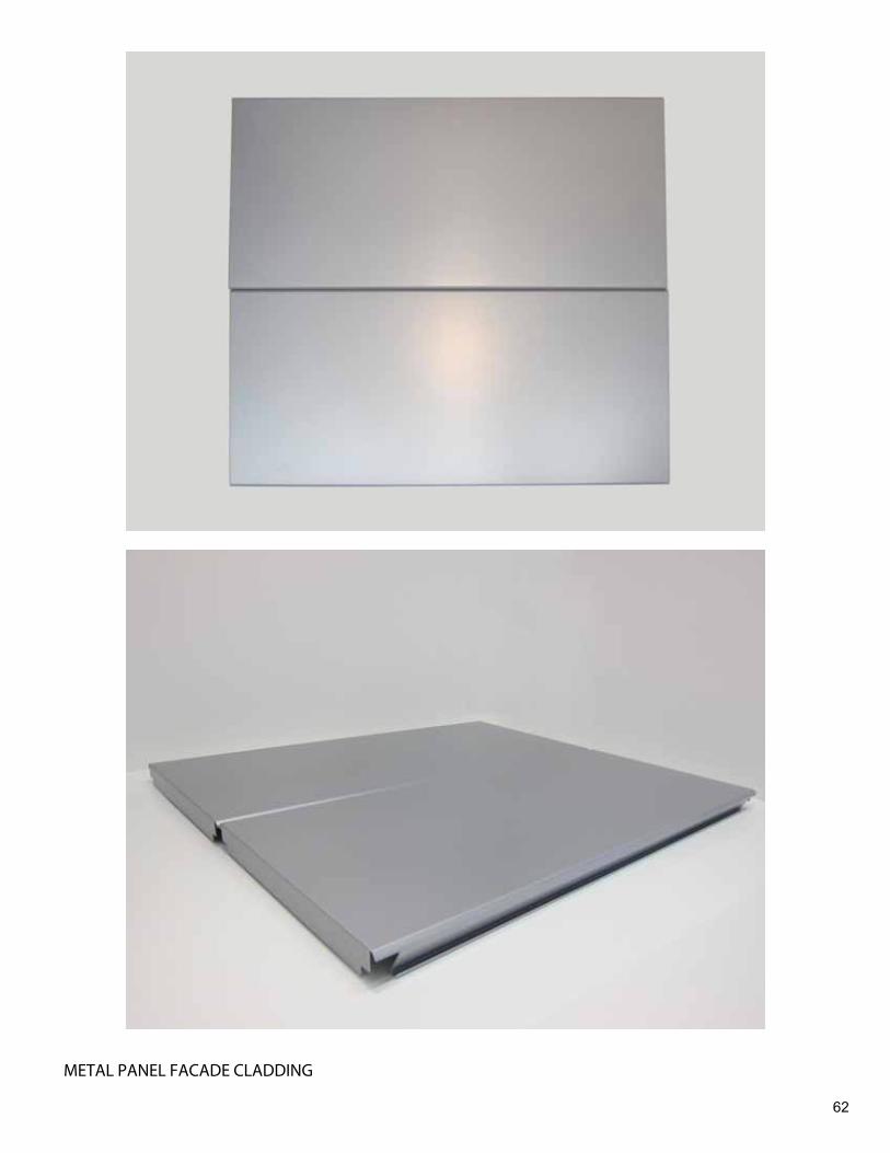
METAL PANEL FACADE CLADDING
63
ALUMINUM WINDOW WALL

E-C
EN
TRIA
LO
GIN
SE
AR
CH
| C
ON
TAC
T U
S |
CH
AT
| CE
NTR
IA C
OM
PA
NIE
S
Hom
eC
ENTR
IA N
ews
Car
eers
His
tory
Arc
hite
ctur
al S
yste
ms
Wal
l Pan
el S
yste
ms
Arc
hite
ctur
al F
oam
Pan
els
Indu
stria
l Foa
m P
anel
sM
etal
Com
posi
tePr
ofile
Ser
ies
Con
cept
Ser
ies
- C
once
aled
Fas
tene
rsIW
Ser
ies
- Con
ceal
ed
Fast
ener
sEx
pose
d Fa
sten
er P
anel
sEc
oScr
een
Perf
orat
ed
Scre
enw
all
Econ
olap
3/4
" (1
9mm
)B
R5-
36M
R3-
36St
yle-
Rib
CS-
260
CS-
660
Insu
late
d C
ompo
site
B
acku
pR
oof P
anel
Sys
tem
sC
oatin
g Sy
stem
sC
oatin
g Se
rvic
esH
HR
Flo
or S
yste
ms
Inte
rnat
iona
lC
ENTR
IA S
ervi
ces
Gro
up
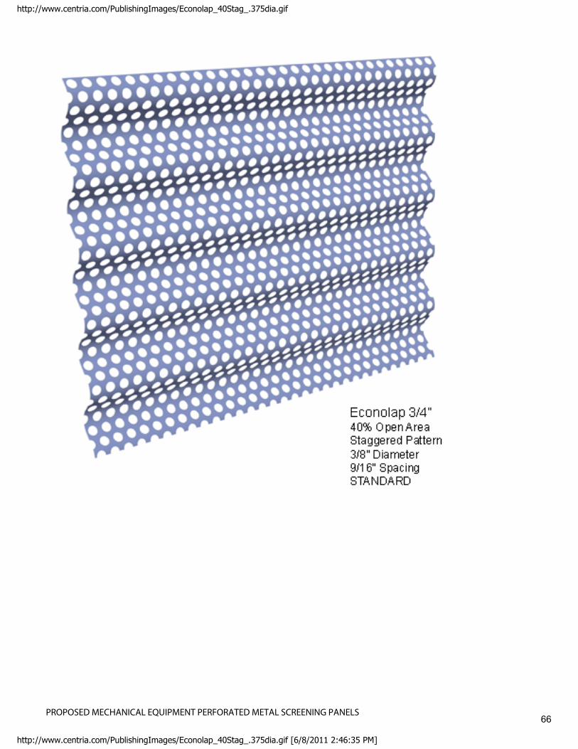
CE
NTR
IA o
ffers
ext
erio
r per
fora
ted
scre
enw
all p
anel
s us
ing
Eco
nola
p 3/
4", B
R5-
36, M
R3-
36, S
tyle
-R
ib, C
S-2
60 a
nd C
S-6
60 in
20
gage
sta
inle
ss s
teel
and
0.0
40" [
1mm
] pai
nted
alu
min
um. T
his
uniq
ue
fabr
icat
ion
prov
ides
a 1
0% to
40%
ope
n ar
ea fo
r the
effe
ct o
f a tr
ansl
ucen
t scr
een
to c
ontro
l lig
ht, a
ir m
ovem
ent a
nd th
e ap
pear
ance
of o
pera
tions
beh
ind
the
scre
en.
Per
fora
ted
scre
enw
alls
can
hel
p bl
end
indu
stria
l and
oth
er fu
nctio
nal a
pplic
atio
ns w
ith th
e su
rrou
ndin
g co
mm
uniti
es.
Patte
rn O
ptio
ns:
Clic
k on
imag
e fo
r lar
ger v
iew
NO
TE:
The
dra
win
g f
iles
bel
ow
are
in
pd
f fo
rmat
. To
do
wn
load
th
e C
AD
fo
rmat
(d
wg
or
zip
), c
lick
her
e to
log
in t
o th
e e-
CEN
TRIA
P
ort
al
Coa
tings
Prod
uct
Spe
cific
atio
ns
Load
Spa
nTa
bles
Gre
en /
Sus
tain
abili
ty
ECO
SCR
EEN
PER
FOR
ATE
DSC
REE
NW
ALL
: EC
ON
OLA
P 3/
4"(1
9mm
)
Page
1of
2H
ome
6/8/
2011
http
://w
ww
.cen
tria.
com
/wal
lpan
els/
ecos
cree
neco
nola
p34i
n/Pa
ges/
defa
ult.a
spx
64PROPOSED MECHANICAL EQUIPMENT PERFORATED METAL SCREENING PANELS

Con
tact
Us
10%
Ope
n A
rea
Rev
erse
Pat
tern
1/
8" [3
mm
] Dia
met
er
3/8"
[10m
m] S
paci
ng
23%
Ope
n A
rea
Sta
gger
ed P
atte
rn
1/8"
[3m
m] D
iam
eter
1/
4" [6
mm
] Spa
cing
23%
Ope
n A
rea
Rev
erse
Pat
tern
1/
4" [6
mm
] Dia
met
er
1/2"
[13m
m] S
paci
ng
30%
Ope
n A
rea
Sta
gger
ed P
atte
rn
1/8"
[3m
m] D
iam
eter
7/
32" [
6mm
] Spa
cing
STA
ND
AR
D
33%
Ope
n A
rea
Sta
gger
ed P
atte
rn
3/16
" [5m
m] D
iam
eter
5/
16" [
8mm
] Spa
cing
40%
Ope
n A
rea
Sta
gger
ed P
atte
rn
1/8"
[3m
m] D
iam
eter
3/
16" [
5mm
] Spa
cing
40%
Ope
n A
rea
Stag
gere
d Pa
ttern
3/
8" [1
0mm
] Dia
met
er
9/16
" [1
4mm
] Spa
cing
STA
ND
AR
D
Site
Map
| Le
gal
CEN
TRIA
©20
10 A
ll rig
hts
rese
rved
.
Page
2of
2H
ome
6/8/
2011
http
://w
ww
.cen
tria.
com
/wal
lpan
els/
ecos
cree
neco
nola
p34i
n/Pa
ges/
defa
ult.a
spx
65PROPOSED MECHANICAL EQUIPMENT PERFORATED METAL SCREENING PANELS
http://www.centria.com/PublishingImages/Econolap_40Stag_.375dia.gif
http://www.centria.com/PublishingImages/Econolap_40Stag_.375dia.gif [6/8/2011 2:46:35 PM]
66PROPOSED MECHANICAL EQUIPMENT PERFORATED METAL SCREENING PANELS


