AX9-4250252-000/001 - 1 - Cobham Semiconductor Solutions Version 1.0.4 www.cobham.com/HiRel Standard Product LEON Expandable Application Platform (LEAP) LEAP Board Stack User Manual Cobham.com/HiRel November 28, 2017 The most important thing we build is trust
Transcript
AX9-4250252-000/001 - 1 - Cobham Semiconductor Solutions Version 1.0.4 www.cobham.com/HiRel
Standard Product
LEON Expandable Application Platform (LEAP) LEAP Board Stack User Manual Cobham.com/HiRel
AX9-4250252-000/001 - 4 - Cobham Semiconductor Solutions Version 1.0.4 www.cobham.com/HiRel
Chapter 1: Introduction
1.1 Scope
This document describes the Leon Expandable Application Platform (LEAP) design implemented
for the Cobham UT700 LEON3-FT processor. The LEAP card design is intended to be a low-cost development platform to familiarize users with the Cobham UT700 processor, as well as allow
custom expansion based on application requirements.
The following hardware and software components are required to use the LEAP evaluation
board:
PC work station running Windows or Linux
Cobham Gaisler GRMON-Pro
For new users to UT700 software development, the following tools are recommended:
BCC Bare-C LEON Cross-compiler
RCC RTEMS LEON Cross-compiler system
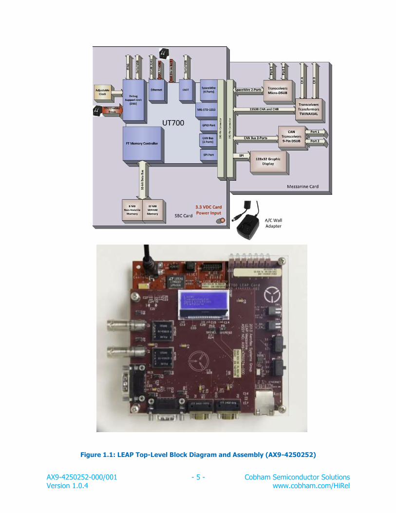
1.2 Cobham LEAP Board Overview
The Cobham LEAP provides a flexible development platform for customers wanting to develop
software that works on the Cobham UT700 Standard Product with minimal cost investment. The Cobham LEAP has the following features:
A Cobham UT700 LEON 3 FT standard product
8 Mbytes NV memory storage
32 Mbytes SDRAM
One USB UART interface via standard USB
One 10T/100 Mbit/s Ethernet port
JTAG interface for programming and debug of UT700 LEON 3FT (requires XILINX USB
Platform Cable)
One 192-pin mezzanine card expansion connector
On-board Programmable LEAP main clock
A block diagram of the LEAP card is shown in Figure 1.1.
AX9-4250252-000/001 - 5 - Cobham Semiconductor Solutions Version 1.0.4 www.cobham.com/HiRel
Figure 1.1: LEAP Top-Level Block Diagram and Assembly (AX9-4250252)
AX9-4250252-000/001 - 6 - Cobham Semiconductor Solutions Version 1.0.4 www.cobham.com/HiRel
One LEAP (4350274) card (mezzanine with SPI display, two CAN bus, two SpaceWire
and a dual-redundant CHA/ CHB 1553B ports)
One A/C Wall Adapter
One Euro-style A/C interface plate
One US-style A/C interface plate
One LEAP Board User Guide (CD)
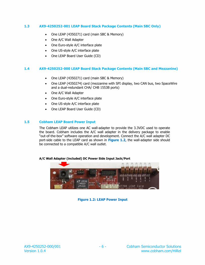
1.5 Cobham LEAP Board Power Input
The Cobham LEAP utilizes one AC wall-adapter to provide the 3.3VDC used to operate
the board. Cobham includes the A/C wall adapter in the delivery package to enable “out-of-the-box” software operation and development. Connect the A/C wall adapter DC
port-side cable to the LEAP card as shown in Figure 1.2, the wall-adapter side should
be connected to a compatible A/C wall outlet.
A/C Wall Adapter (included) DC Power Side Input Jack/Port
Figure 1.2: LEAP Power Input
AX9-4250252-000/001 - 7 - Cobham Semiconductor Solutions Version 1.0.4 www.cobham.com/HiRel
Chapter 2: Architecture
2.1 UT700 Brief Overview
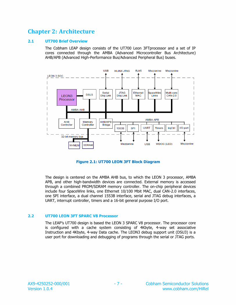
The Cobham LEAP design consists of the UT700 Leon 3FTprocessor and a set of IP
cores connected through the AMBA (Advanced Microcontroller Bus Architecture) AHB/APB (Advanced High-Performance Bus/Advanced Peripheral Bus) buses.
Figure 2.1: UT700 LEON 3FT Block Diagram
The design is centered on the AMBA AHB bus, to which the LEON 3 processor, AMBA APB, and other high-bandwidth devices are connected. External memory is accessed
through a combined PROM/SDRAM memory controller. The on-chip peripheral devices
include four SpaceWire links, one Ethernet 10/100 Mbit MAC, dual CAN-2.0 interfaces, one SPI interface, a dual channel 1553B interface, serial and JTAG debug interfaces, a
UART, interrupt controller, timers and a 16-bit general purpose I/O port.
2.2 UT700 LEON 3FT SPARC V8 Processor
The LEAP’s UT700 design is based the LEON 3 SPARC V8 processor. The processor core is configured with a cache system consisting of 4Kbyte, 4-way set associative
Instruction and 4Kbyte, 4-way Data cache. The LEON3 debug support unit (DSU3) is a
user port for downloading and debugging of programs through the serial or JTAG ports.
AX9-4250252-000/001 - 8 - Cobham Semiconductor Solutions Version 1.0.4 www.cobham.com/HiRel
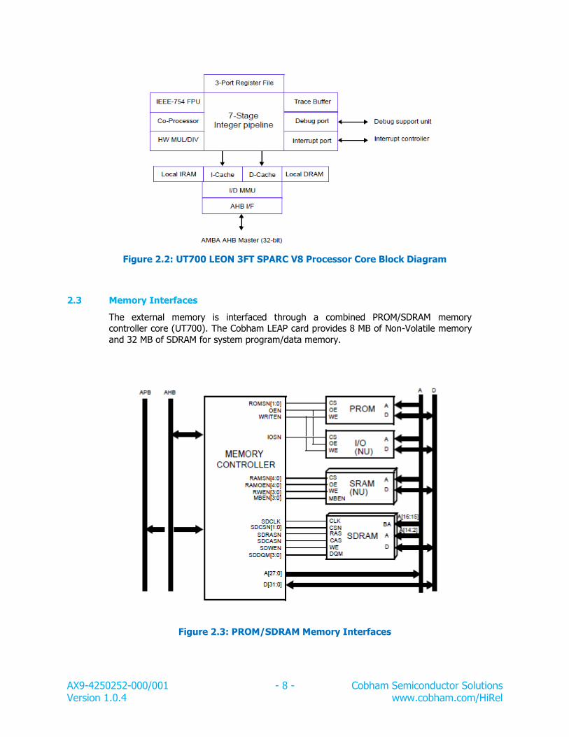
The external memory is interfaced through a combined PROM/SDRAM memory controller core (UT700). The Cobham LEAP card provides 8 MB of Non-Volatile memory
and 32 MB of SDRAM for system program/data memory.
Figure 2.3: PROM/SDRAM Memory Interfaces
AX9-4250252-000/001 - 9 - Cobham Semiconductor Solutions Version 1.0.4 www.cobham.com/HiRel
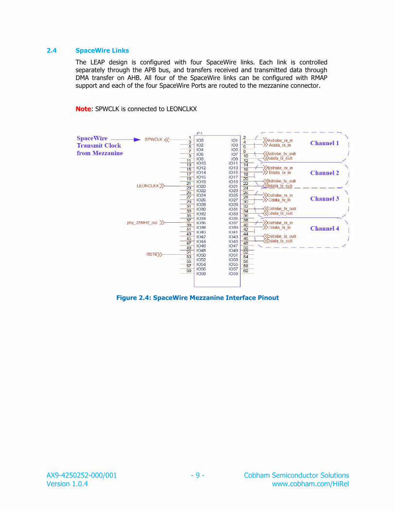
2.4 SpaceWire Links
The LEAP design is configured with four SpaceWire links. Each link is controlled separately through the APB bus, and transfers received and transmitted data through
DMA transfer on AHB. All four of the SpaceWire links can be configured with RMAP support and each of the four SpaceWire Ports are routed to the mezzanine connector.
Note: SPWCLK is connected to LEONCLKX
Figure 2.4: SpaceWire Mezzanine Interface Pinout
AX9-4250252-000/001 - 10 - Cobham Semiconductor Solutions Version 1.0.4 www.cobham.com/HiRel
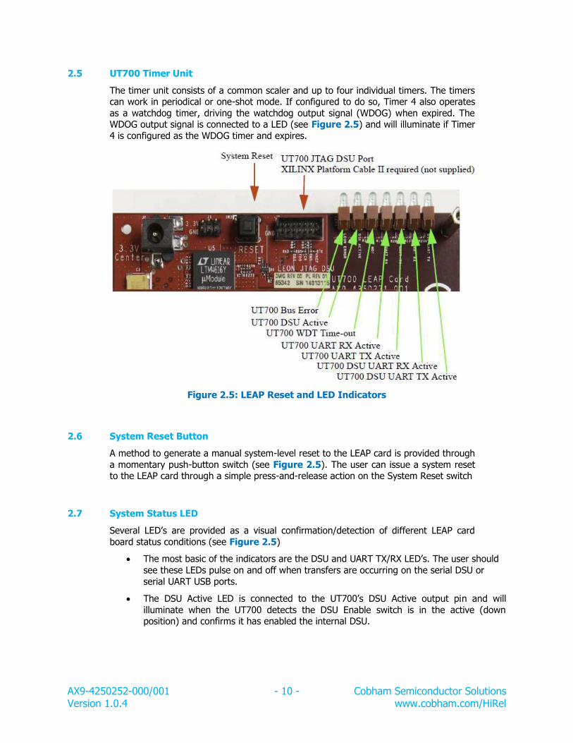
2.5 UT700 Timer Unit
The timer unit consists of a common scaler and up to four individual timers. The timers can work in periodical or one-shot mode. If configured to do so, Timer 4 also operates
as a watchdog timer, driving the watchdog output signal (WDOG) when expired. The WDOG output signal is connected to a LED (see Figure 2.5) and will illuminate if Timer
4 is configured as the WDOG timer and expires.
Figure 2.5: LEAP Reset and LED Indicators
2.6 System Reset Button
A method to generate a manual system-level reset to the LEAP card is provided through
a momentary push-button switch (see Figure 2.5). The user can issue a system reset to the LEAP card through a simple press-and-release action on the System Reset switch
2.7 System Status LED
Several LED’s are provided as a visual confirmation/detection of different LEAP card
board status conditions (see Figure 2.5)
The most basic of the indicators are the DSU and UART TX/RX LED’s. The user should
see these LEDs pulse on and off when transfers are occurring on the serial DSU or
serial UART USB ports.
The DSU Active LED is connected to the UT700’s DSU Active output pin and will
illuminate when the UT700 detects the DSU Enable switch is in the active (down position) and confirms it has enabled the internal DSU.
AX9-4250252-000/001 - 11 - Cobham Semiconductor Solutions Version 1.0.4 www.cobham.com/HiRel
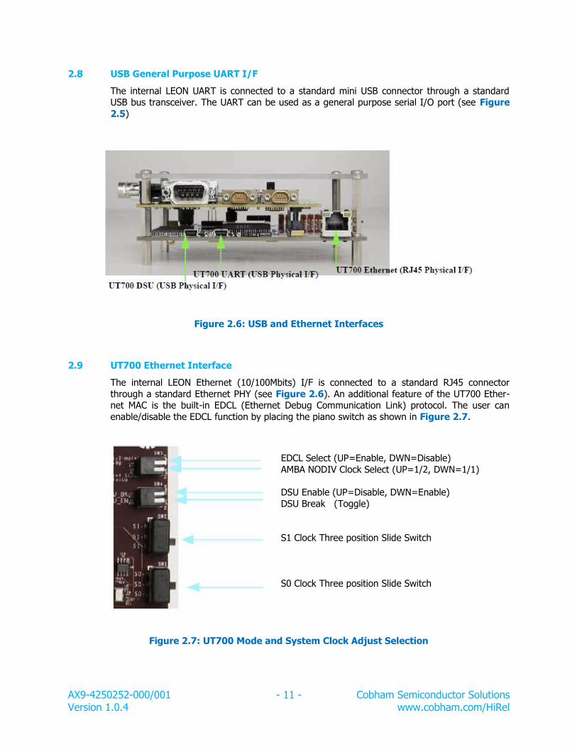
2.8 USB General Purpose UART I/F
The internal LEON UART is connected to a standard mini USB connector through a standard USB bus transceiver. The UART can be used as a general purpose serial I/O port (see Figure
2.5)
Figure 2.6: USB and Ethernet Interfaces
2.9 UT700 Ethernet Interface
The internal LEON Ethernet (10/100Mbits) I/F is connected to a standard RJ45 connector
through a standard Ethernet PHY (see Figure 2.6). An additional feature of the UT700 Ether-net MAC is the built-in EDCL (Ethernet Debug Communication Link) protocol. The user can
enable/disable the EDCL function by placing the piano switch as shown in Figure 2.7.
Figure 2.7: UT700 Mode and System Clock Adjust Selection
EDCL Select (UP=Enable, DWN=Disable)
AMBA NODIV Clock Select (UP=1/2, DWN=1/1)
DSU Enable (UP=Disable, DWN=Enable)
DSU Break (Toggle)
S1 Clock Three position Slide Switch
S0 Clock Three position Slide Switch
AX9-4250252-000/001 - 12 - Cobham Semiconductor Solutions Version 1.0.4 www.cobham.com/HiRel
2.10 System Clock Selection
Two switches (S0 and S1) control the main clock frequency input to the UT700 (see Figure 2.7). For this application, the maximum operating clock that can be selected for the UT700
with the AMBA NODIV piano switch (see Figure 2.7) set to the down (1/1) position is 133MHz. The positions listed in Table 2.1 outline the valid S0 and S1 position combinations and
corresponding UT700 AMBA frequencies.
Table 2.1: System Clock Selection
S1 Position
S0 Position
NODIV
AMBA Frequency
H M Up/Down 37.50 MHz/75.00 MHz
M H Up/Down 41.67 MHz/83.33 MHz
L H Up/Down 62.50 MHz/125.0 MHz
L M Up/Down 66.65 MHz/133.3 MHz
H L Up/Down 75.00 MHz/Not Valid
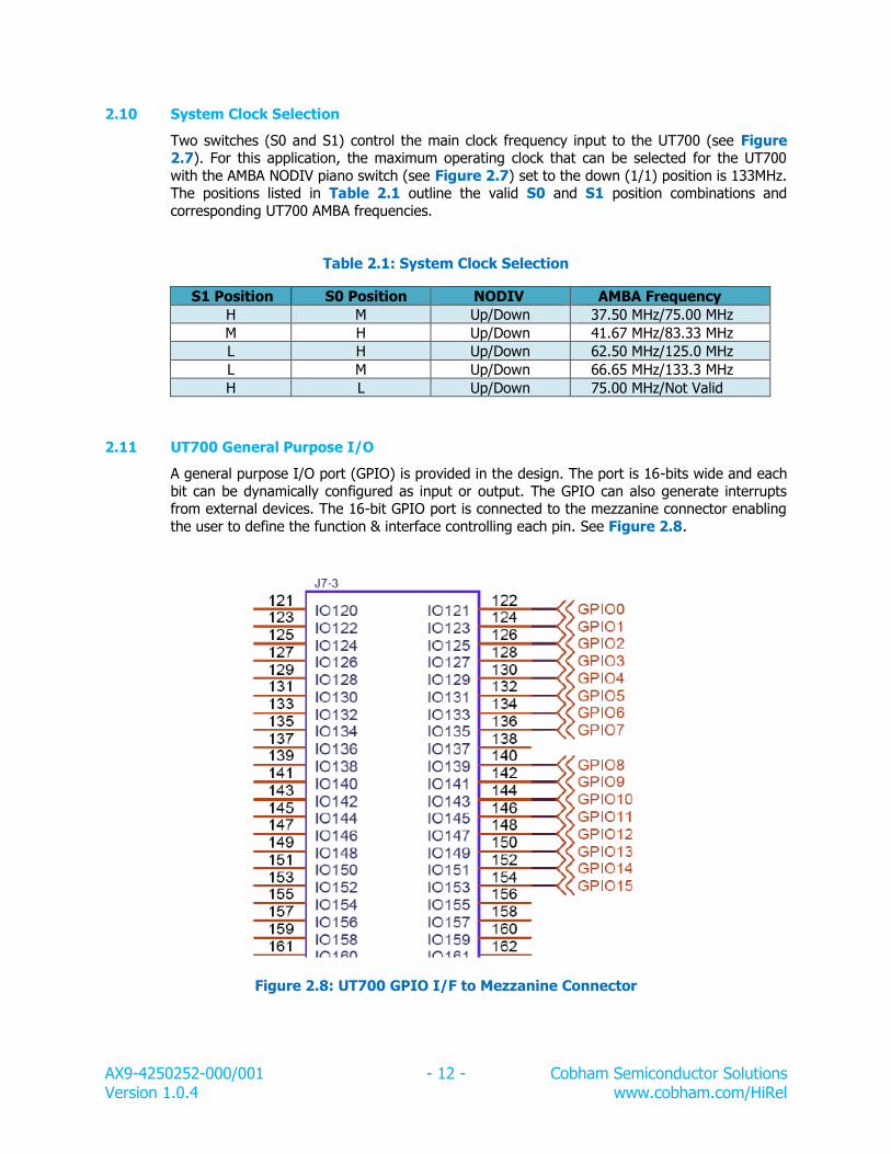
2.11 UT700 General Purpose I/O
A general purpose I/O port (GPIO) is provided in the design. The port is 16-bits wide and each
bit can be dynamically configured as input or output. The GPIO can also generate interrupts from external devices. The 16-bit GPIO port is connected to the mezzanine connector enabling
the user to define the function & interface controlling each pin. See Figure 2.8.
Figure 2.8: UT700 GPIO I/F to Mezzanine Connector
AX9-4250252-000/001 - 13 - Cobham Semiconductor Solutions Version 1.0.4 www.cobham.com/HiRel
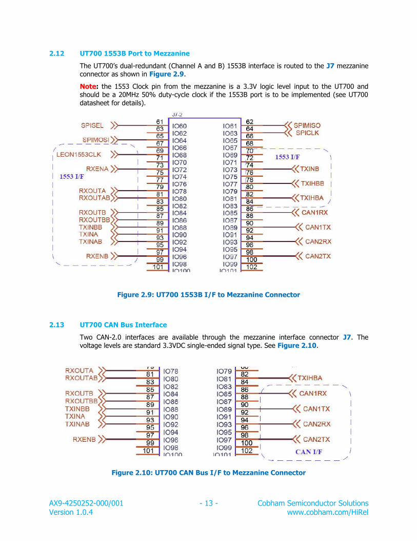
2.12 UT700 1553B Port to Mezzanine
The UT700’s dual-redundant (Channel A and B) 1553B interface is routed to the J7 mezzanine connector as shown in Figure 2.9.
Note: the 1553 Clock pin from the mezzanine is a 3.3V logic level input to the UT700 and should be a 20MHz 50% duty-cycle clock if the 1553B port is to be implemented (see UT700
datasheet for details).
Figure 2.9: UT700 1553B I/F to Mezzanine Connector
2.13 UT700 CAN Bus Interface
Two CAN-2.0 interfaces are available through the mezzanine interface connector J7. The
voltage levels are standard 3.3VDC single-ended signal type. See Figure 2.10.
Figure 2.10: UT700 CAN Bus I/F to Mezzanine Connector
AX9-4250252-000/001 - 14 - Cobham Semiconductor Solutions Version 1.0.4 www.cobham.com/HiRel
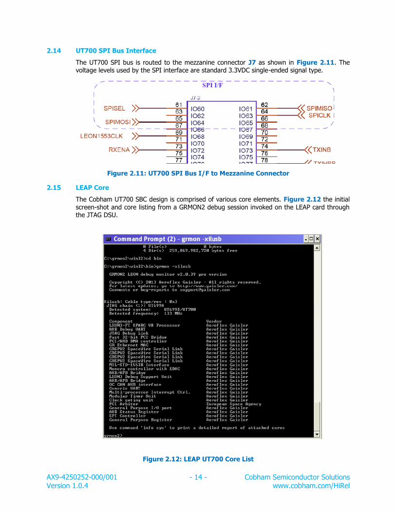
2.14 UT700 SPI Bus Interface
The UT700 SPI bus is routed to the mezzanine connector J7 as shown in Figure 2.11. The voltage levels used by the SPI interface are standard 3.3VDC single-ended signal type.
Figure 2.11: UT700 SPI Bus I/F to Mezzanine Connector
2.15 LEAP Core
The Cobham UT700 SBC design is comprised of various core elements. Figure 2.12 the initial
screen-shot and core listing from a GRMON2 debug session invoked on the LEAP card through the JTAG DSU.
Figure 2.12: LEAP UT700 Core List
AX9-4250252-000/001 - 15 - Cobham Semiconductor Solutions Version 1.0.4 www.cobham.com/HiRel
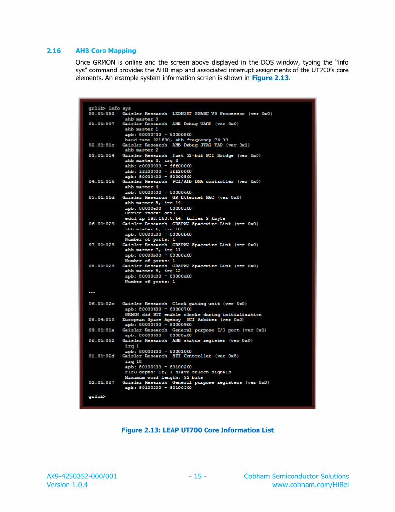
2.16 AHB Core Mapping
Once GRMON is online and the screen above displayed in the DOS window, typing the “info sys” command provides the AHB map and associated interrupt assignments of the UT700’s core
elements. An example system information screen is shown in Figure 2.13.
Figure 2.13: LEAP UT700 Core Information List
AX9-4250252-000/001 - 16 - Cobham Semiconductor Solutions Version 1.0.4 www.cobham.com/HiRel
2.17 Non-Volatile Memory Mapping
The LEAP card offers the user access to 8Mbytes of contiguous Non-Volatile (NV) memory storage. The base address for the 32-bit wide PROM space is 0x0000_0000. The user has the
ability to write data into the NV memory by setting the PROM write enable bit in the UT700 memory configuration register (see UT700 Datasheet for details).
Note: MRAM 4x MR4A16B
2.18 SDRAM Memory Mapping
The LEAP card offers the user access to 32Mbytes of contiguous volatile memory storage. The
base address for the 32-bit wide SDRAM space is 0x4000_0000; all programs targeting the
LEAP card should compile programs using this base address.
Note: SDRAM 1x IS42S32800D
AX9-4250252-000/001 - 17 - Cobham Semiconductor Solutions Version 1.0.4 www.cobham.com/HiRel
Chapter 3: Mezzanine Power Interface
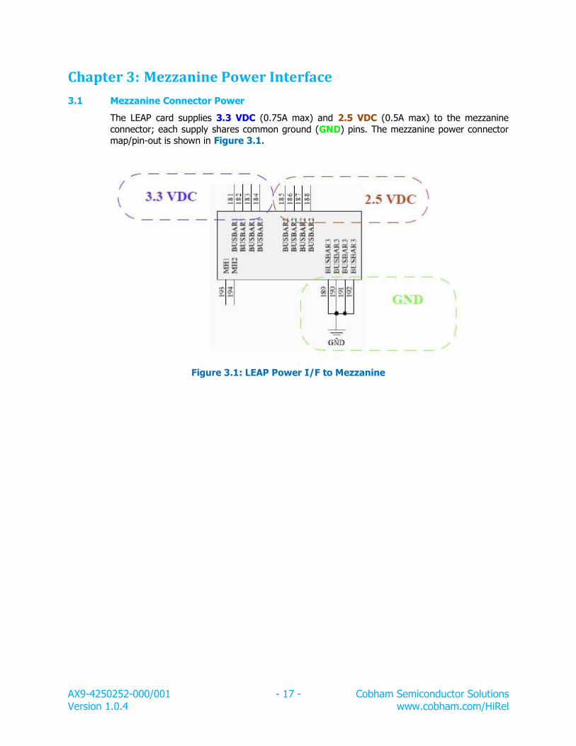
3.1 Mezzanine Connector Power
The LEAP card supplies 3.3 VDC (0.75A max) and 2.5 VDC (0.5A max) to the mezzanine
connector; each supply shares common ground (GND) pins. The mezzanine power connector map/pin-out is shown in Figure 3.1.
Figure 3.1: LEAP Power I/F to Mezzanine
AX9-4250252-000/001 - 18 - Cobham Semiconductor Solutions Version 1.0.4 www.cobham.com/HiRel
Chapter 4: Optional LEAP with Mezzanine Card
Base PN: 4250252-000
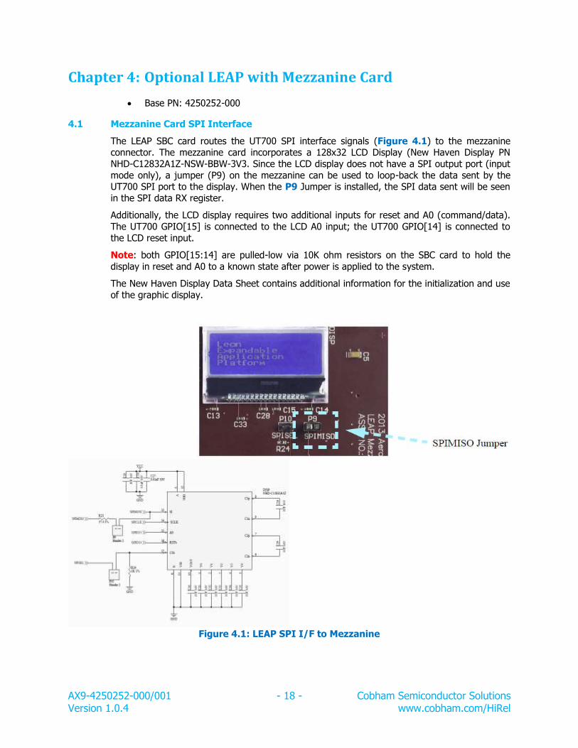
4.1 Mezzanine Card SPI Interface
The LEAP SBC card routes the UT700 SPI interface signals (Figure 4.1) to the mezzanine connector. The mezzanine card incorporates a 128x32 LCD Display (New Haven Display PN
NHD-C12832A1Z-NSW-BBW-3V3. Since the LCD display does not have a SPI output port (input
mode only), a jumper (P9) on the mezzanine can be used to loop-back the data sent by the UT700 SPI port to the display. When the P9 Jumper is installed, the SPI data sent will be seen
in the SPI data RX register.
Additionally, the LCD display requires two additional inputs for reset and A0 (command/data).
The UT700 GPIO[15] is connected to the LCD A0 input; the UT700 GPIO[14] is connected to
the LCD reset input.
Note: both GPIO[15:14] are pulled-low via 10K ohm resistors on the SBC card to hold the
display in reset and A0 to a known state after power is applied to the system.
The New Haven Display Data Sheet contains additional information for the initialization and use
of the graphic display.
Figure 4.1: LEAP SPI I/F to Mezzanine
AX9-4250252-000/001 - 19 - Cobham Semiconductor Solutions Version 1.0.4 www.cobham.com/HiRel
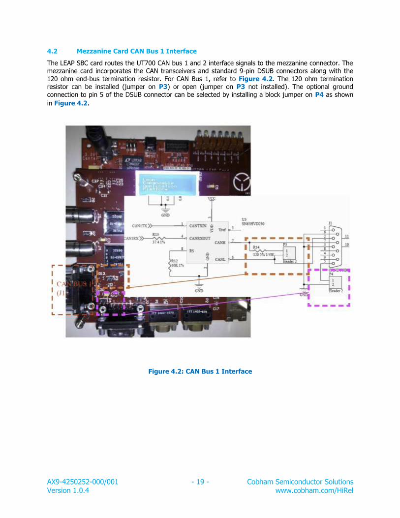
4.2 Mezzanine Card CAN Bus 1 Interface
The LEAP SBC card routes the UT700 CAN bus 1 and 2 interface signals to the mezzanine connector. The mezzanine card incorporates the CAN transceivers and standard 9-pin DSUB connectors along with the
120 ohm end-bus termination resistor. For CAN Bus 1, refer to Figure 4.2. The 120 ohm termination resistor can be installed (jumper on P3) or open (jumper on P3 not installed). The optional ground
connection to pin 5 of the DSUB connector can be selected by installing a block jumper on P4 as shown
in Figure 4.2.
Figure 4.2: CAN Bus 1 Interface
AX9-4250252-000/001 - 20 - Cobham Semiconductor Solutions Version 1.0.4 www.cobham.com/HiRel
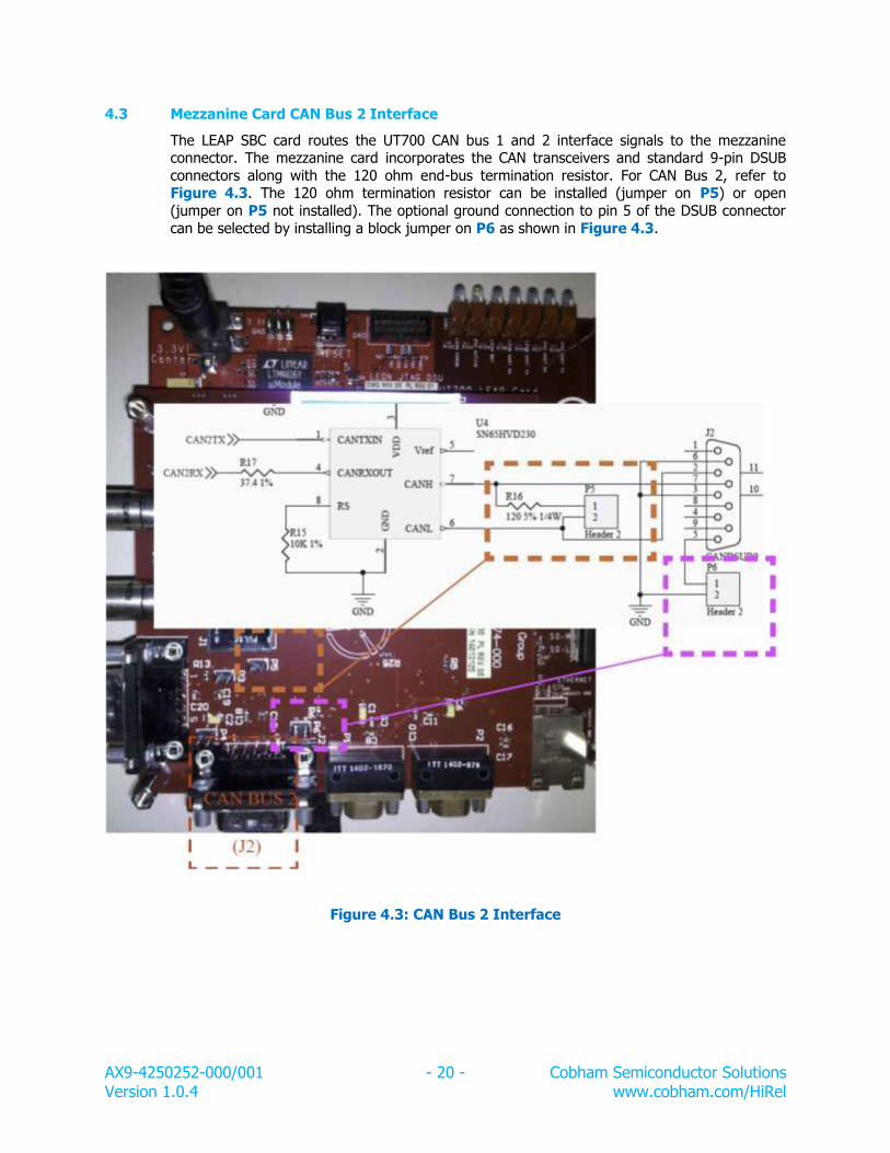
4.3 Mezzanine Card CAN Bus 2 Interface
The LEAP SBC card routes the UT700 CAN bus 1 and 2 interface signals to the mezzanine connector. The mezzanine card incorporates the CAN transceivers and standard 9-pin DSUB
connectors along with the 120 ohm end-bus termination resistor. For CAN Bus 2, refer to Figure 4.3. The 120 ohm termination resistor can be installed (jumper on P5) or open
(jumper on P5 not installed). The optional ground connection to pin 5 of the DSUB connector
can be selected by installing a block jumper on P6 as shown in Figure 4.3.
Figure 4.3: CAN Bus 2 Interface
AX9-4250252-000/001 - 21 - Cobham Semiconductor Solutions Version 1.0.4 www.cobham.com/HiRel
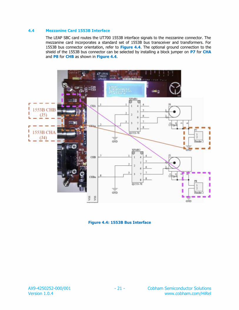
4.4 Mezzanine Card 1553B Interface
The LEAP SBC card routes the UT700 1553B interface signals to the mezzanine connector. The mezzanine card incorporates a standard set of 1553B bus transceiver and transformers. For
1553B bus connector orientation, refer to Figure 4.4. The optional ground connection to the shield of the 1553B bus connector can be selected by installing a block jumper on P7 for CHA
and P8 for CHB as shown in Figure 4.4.
Figure 4.4: 1553B Bus Interface
AX9-4250252-000/001 - 22 - Cobham Semiconductor Solutions Version 1.0.4 www.cobham.com/HiRel
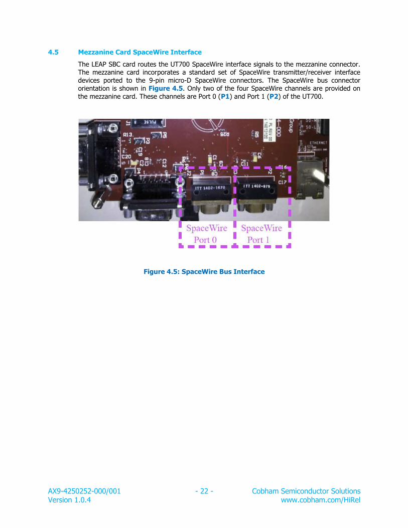
4.5 Mezzanine Card SpaceWire Interface
The LEAP SBC card routes the UT700 SpaceWire interface signals to the mezzanine connector. The mezzanine card incorporates a standard set of SpaceWire transmitter/receiver interface
devices ported to the 9-pin micro-D SpaceWire connectors. The SpaceWire bus connector orientation is shown in Figure 4.5. Only two of the four SpaceWire channels are provided on
the mezzanine card. These channels are Port 0 (P1) and Port 1 (P2) of the UT700.
Figure 4.5: SpaceWire Bus Interface
AX9-4250252-000/001 - 23 - Cobham Semiconductor Solutions Version 1.0.4 www.cobham.com/HiRel
Chapter 5: Software Development
5.1 “Out of the Box” Experience
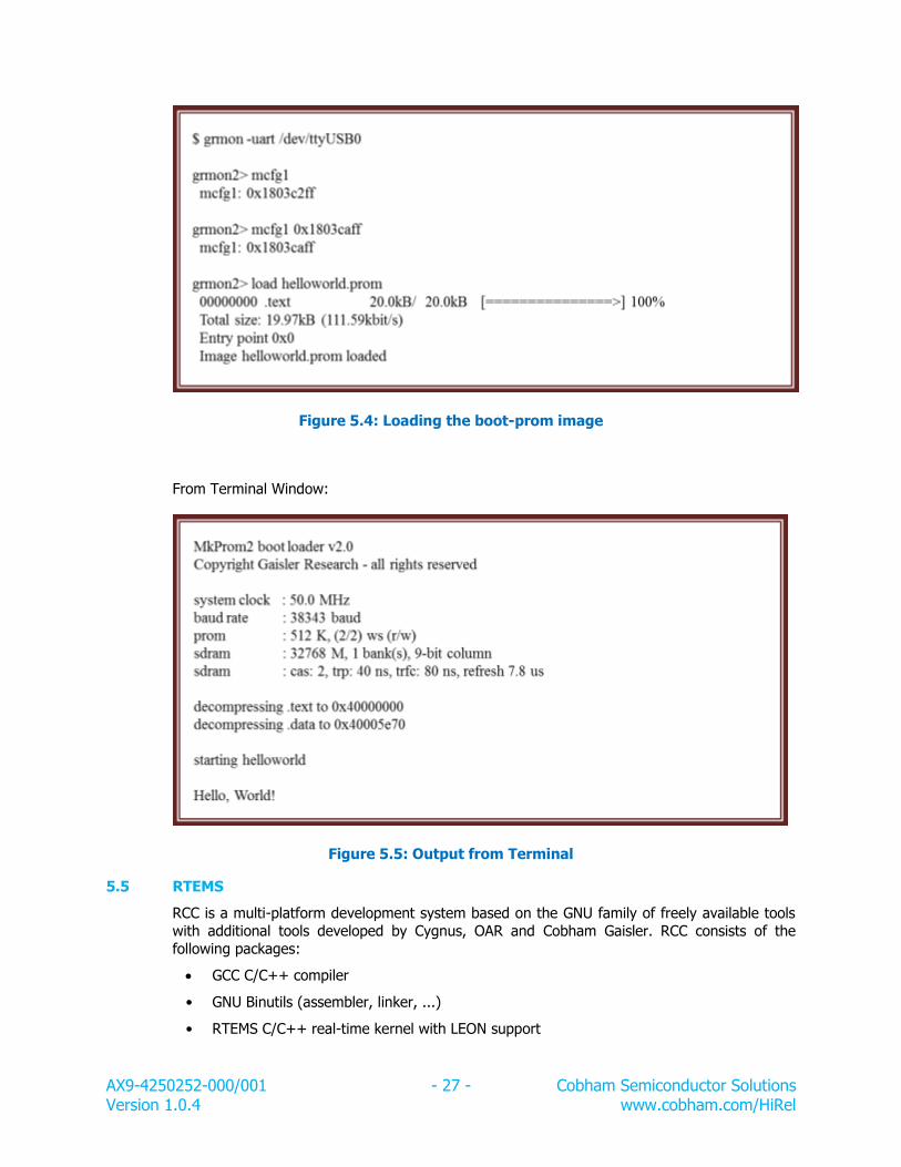
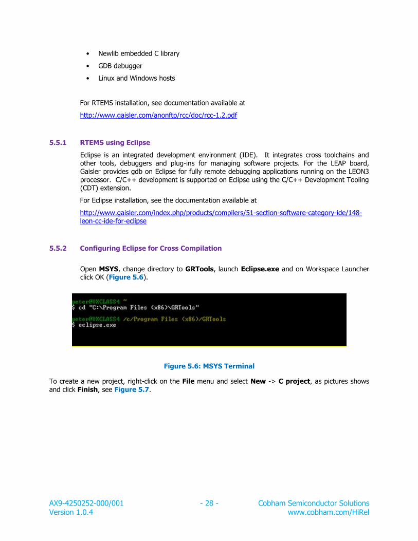
The LEAP board comes preloaded with a “hello world” program, and after applying power to the board, it will display the “hello world” message on the Terminal, see Figure 5.5. To
display messages on the Terminal, the LEAP board connects over a USB serial connection
(UT700 UART), see Figure 2.6, with the following information.
Connection Speed: Default baud for the LEAP board is 38,400
Other options Data: 8
Stop bits: 1 Parity: none
Flow control: No
5.2 Tool Chains
The LEON3 processor is supported by several software tool chains:
Bare-C cross-compiler system (BCC)
RTEMS cross-compiler system (RCC)
Linux
eCos real-time kernel
VxWorks
ThreadX
All these tool chains and associated documentation can be obtained from www.gaisler.com.
5.3 Downloading Software to the Target System
LEON3 has an on-chip debug support unit (DSU) which greatly simplifies the debugging of
software on a target system. The DSU provides full access to all processor registers and system memory and also includes instruction and data trace buffers. Downloading and debugging of
software is done using the GRMON debug monitor, a tool that runs on the host computer and
communicates with the target through either serial or JTAG interfaces.
Please refer to the GRMON User’s Manual for a description of the GRMON operations at
www.gaisler.com.
5.4 Bare-C cross-compiler system
The Bare-C (BCC) cross toolchain is a set of software tools for building computer software.
The software is built on a host computer but builds programs to run on LEON3 processors, i.e.,
BCC provides all the different phases that all programs go through: compiler, assembler and
linker. The compiler transforms the C program into an assembly language program. The assembler transforms the assembly language into an object file, which contains the file header,
text segment, data segment, relocation information and debugging information. Finally, the
linker places code and data modules symbolically in memory; determines the addresses of data and instruction labels; and patches both the internal and external references.
AX9-4250252-000/001 - 25 - Cobham Semiconductor Solutions Version 1.0.4 www.cobham.com/HiRel
BCC useful options for compiling applications are:
-g generate debugging information - must be used for debugging with GDB
-msoft-float emulate floating-point - must be used if no FPU exists in the system -mcpu=v8 generate SPARC V8 mul/div instructions - needs hardware multiply and
divide
-O2, -O3 or -Os optimize code for maximum performance or minimal code size -qsvt use the single-vector trap model
-mtune=ut699 set UT699 specific parameters (gcc-3.4.4 and gcc-4.4.2) -mfix-b2bst enable workarounds for LEON3FT store-store errata (GRLIB-TN-0009)
-mflat do not use register windows (i.e. no save/restore instructions)
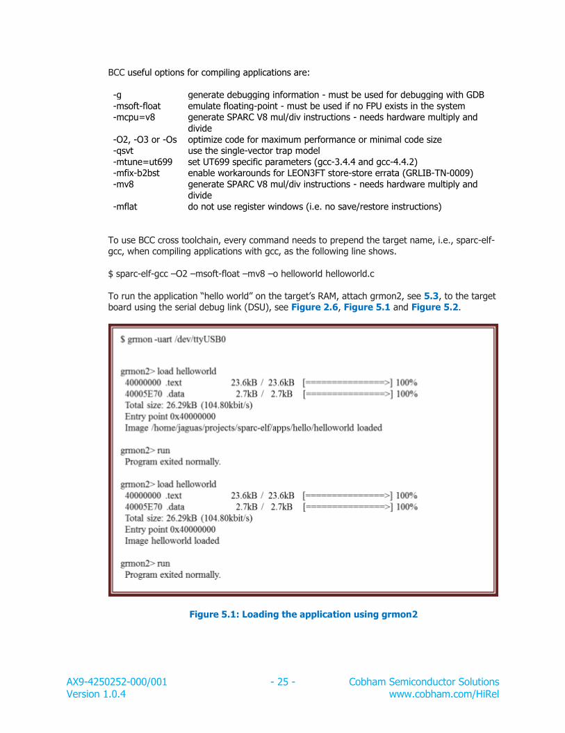
To use BCC cross toolchain, every command needs to prepend the target name, i.e., sparc-elf-gcc, when compiling applications with gcc, as the following line shows.
To run the application “hello world” on the target’s RAM, attach grmon2, see 5.3, to the target board using the serial debug link (DSU), see Figure 2.6, Figure 5.1 and Figure 5.2.
Figure 5.1: Loading the application using grmon2
AX9-4250252-000/001 - 26 - Cobham Semiconductor Solutions Version 1.0.4 www.cobham.com/HiRel
From Terminal Window:
Figure 5.2: Application output from Terminal
5.4.3 Booting with mkprom2
Once the application is compiled with BCC, mkprom2 can create a boot-image to run from
PROM on the LEON3 processor. Mkprom2 utility is freely available at:
www.gaisler.com.
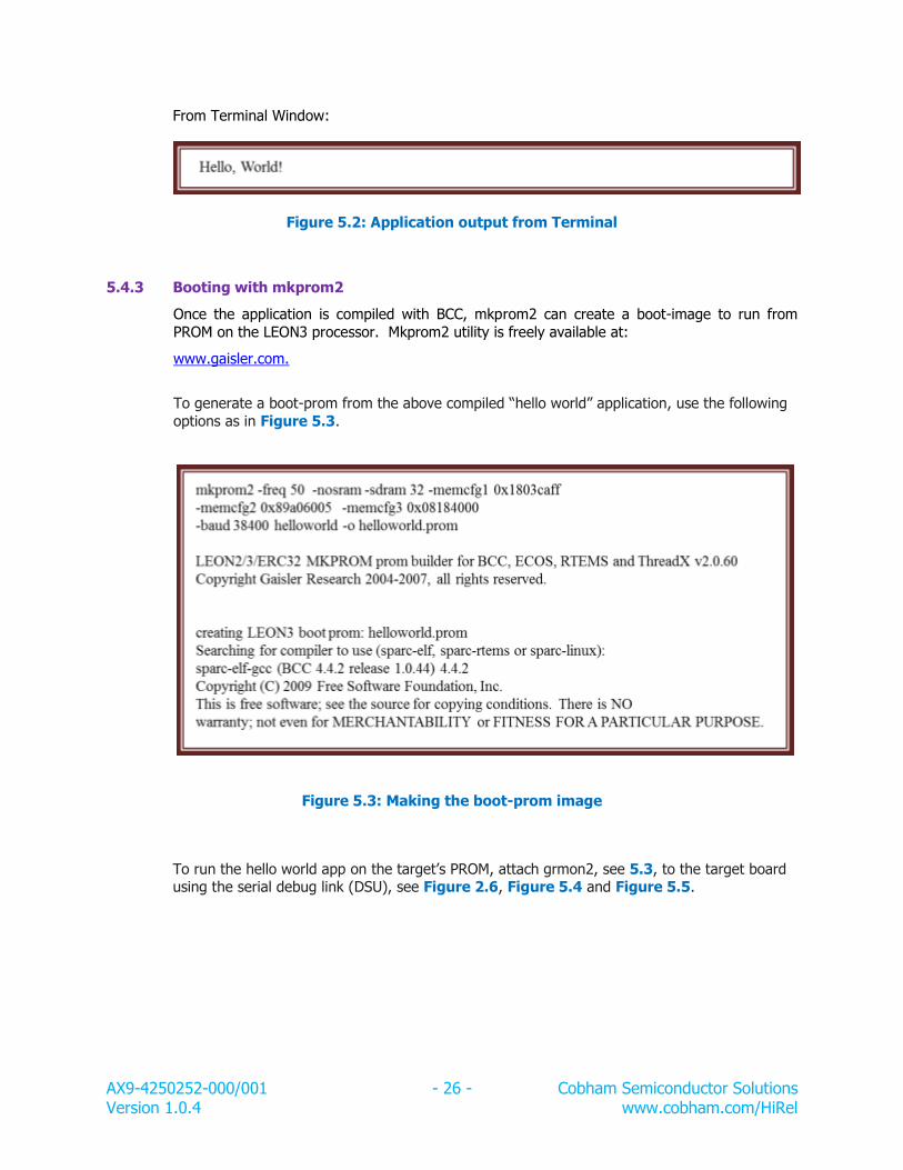
To generate a boot-prom from the above compiled “hello world” application, use the following
options as in Figure 5.3.
Figure 5.3: Making the boot-prom image
To run the hello world app on the target’s PROM, attach grmon2, see 5.3, to the target board using the serial debug link (DSU), see Figure 2.6, Figure 5.4 and Figure 5.5.
Eclipse is an integrated development environment (IDE). It integrates cross toolchains and
other tools, debuggers and plug-ins for managing software projects. For the LEAP board, Gaisler provides gdb on Eclipse for fully remote debugging applications running on the LEON3
processor. C/C++ development is supported on Eclipse using the C/C++ Development Tooling (CDT) extension.
For Eclipse installation, see the documentation available at
AX9-4250252-000/001 - 29 - Cobham Semiconductor Solutions Version 1.0.4 www.cobham.com/HiRel
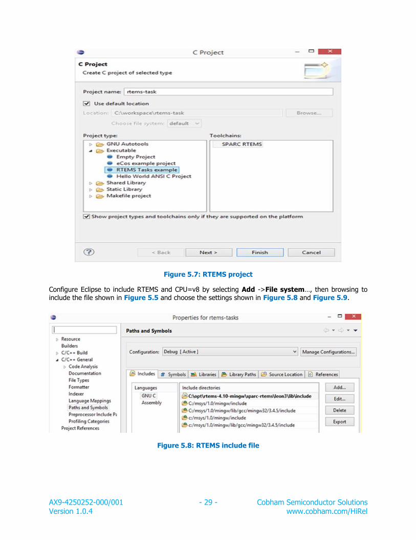
Figure 5.7: RTEMS project
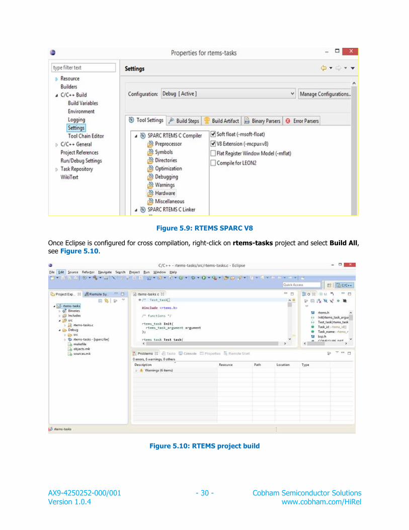
Configure Eclipse to include RTEMS and CPU=v8 by selecting Add ->File system…, then browsing to include the file shown in Figure 5.5 and choose the settings shown in Figure 5.8 and Figure 5.9.
Figure 5.8: RTEMS include file
AX9-4250252-000/001 - 30 - Cobham Semiconductor Solutions Version 1.0.4 www.cobham.com/HiRel
Figure 5.9: RTEMS SPARC V8
Once Eclipse is configured for cross compilation, right-click on rtems-tasks project and select Build All,
see Figure 5.10.
Figure 5.10: RTEMS project build
AX9-4250252-000/001 - 31 - Cobham Semiconductor Solutions Version 1.0.4 www.cobham.com/HiRel
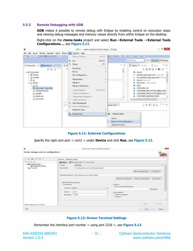
5.5.3 Remote Debugging with GDB
GDB makes it possible to remote debug with Eclipse by enabling control on execution steps and viewing debug messages and memory values directly from within Eclipse on the desktop.
Right-click on the rtems-tasks project and select Run->External Tools ->External Tools Configurations…, see Figure 5.11.
Figure 5.11: External Configurations
Specify the right com port < com3 > under Device and click Run, see Figure 5.12.
Figure 5.12: Grmon Terminal Settings
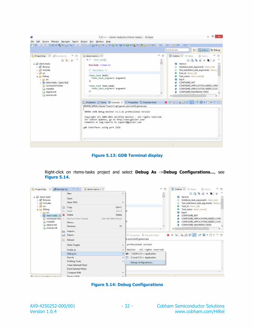
Remember the interface port number < using port 2226 >, see Figure 5.13.
AX9-4250252-000/001 - 32 - Cobham Semiconductor Solutions Version 1.0.4 www.cobham.com/HiRel
Figure 5.13: GDB Terminal display
Right-click on rtems-tasks project and select Debug As ->Debug Configurations…, see
Figure 5.14.
Figure 5.14: Debug Configurations
AX9-4250252-000/001 - 33 - Cobham Semiconductor Solutions Version 1.0.4 www.cobham.com/HiRel
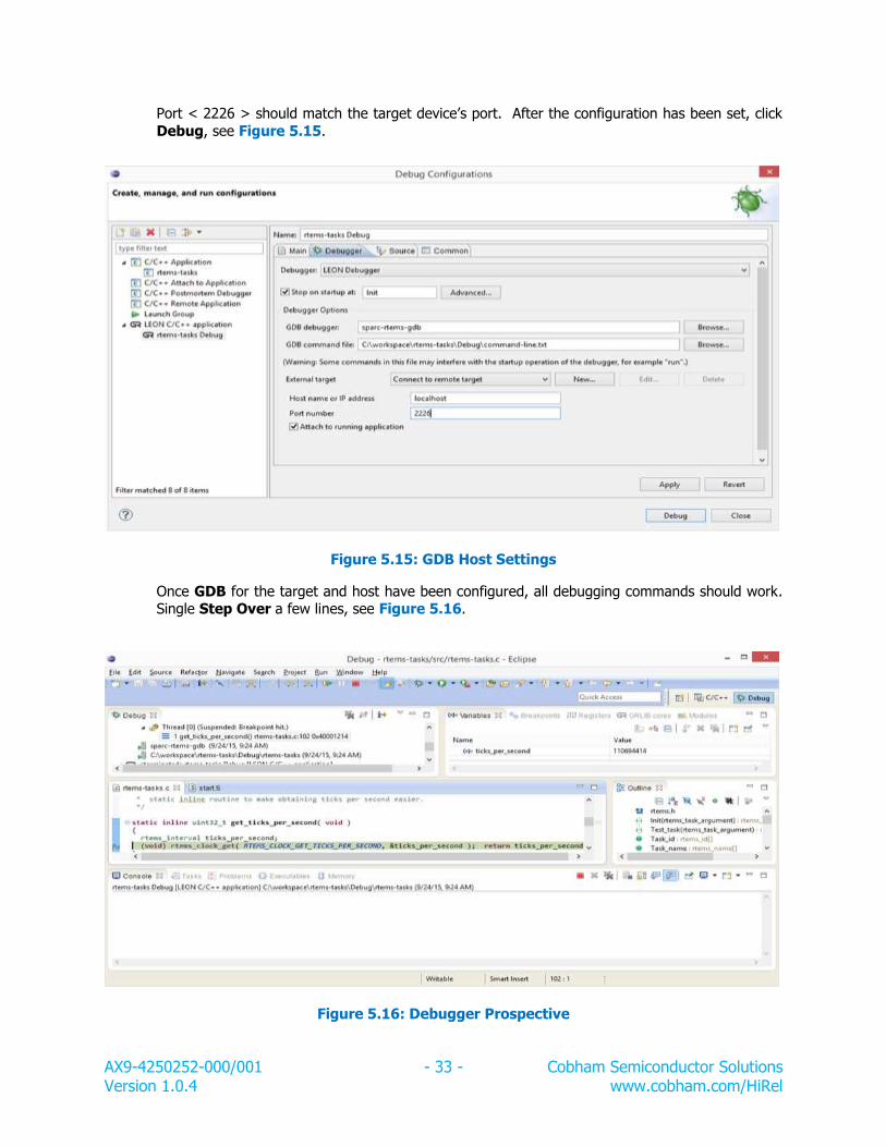
Port < 2226 > should match the target device’s port. After the configuration has been set, click
Debug, see Figure 5.15.
Figure 5.15: GDB Host Settings
Once GDB for the target and host have been configured, all debugging commands should work. Single Step Over a few lines, see Figure 5.16.
Figure 5.16: Debugger Prospective
AX9-4250252-000/001 - 34 - Cobham Semiconductor Solutions Version 1.0.4 www.cobham.com/HiRel
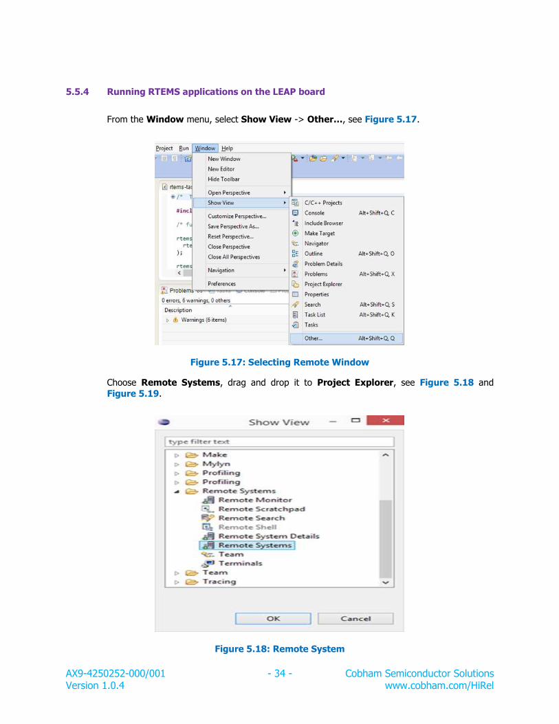
5.5.4 Running RTEMS applications on the LEAP board
From the Window menu, select Show View -> Other…, see Figure 5.17.
Figure 5.17: Selecting Remote Window
Choose Remote Systems, drag and drop it to Project Explorer, see Figure 5.18 and
Figure 5.19.
Figure 5.18: Remote System
AX9-4250252-000/001 - 35 - Cobham Semiconductor Solutions Version 1.0.4 www.cobham.com/HiRel
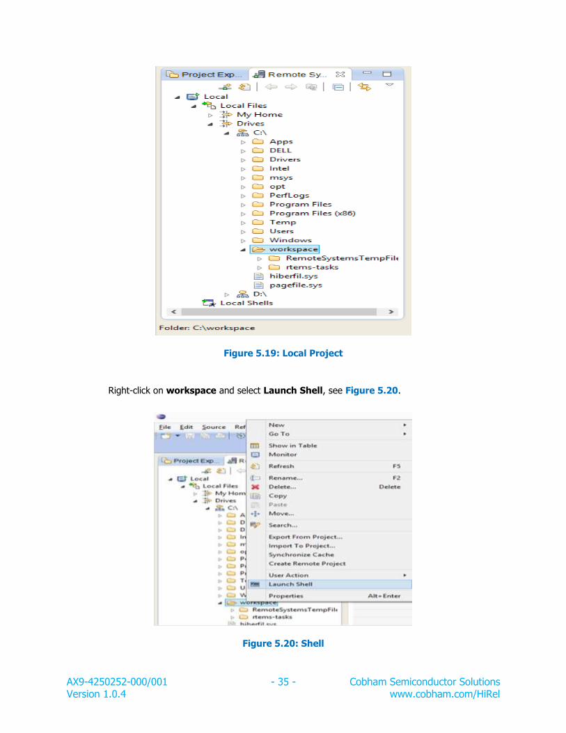
Figure 5.19: Local Project
Right-click on workspace and select Launch Shell, see Figure 5.20.
Figure 5.20: Shell
AX9-4250252-000/001 - 36 - Cobham Semiconductor Solutions Version 1.0.4 www.cobham.com/HiRel
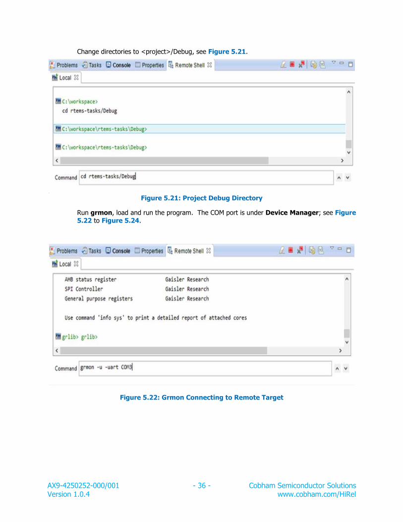
Change directories to <project>/Debug, see Figure 5.21.
Figure 5.21: Project Debug Directory
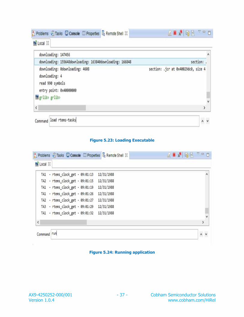
Run grmon, load and run the program. The COM port is under Device Manager; see Figure 5.22 to Figure 5.24.
Figure 5.22: Grmon Connecting to Remote Target
AX9-4250252-000/001 - 37 - Cobham Semiconductor Solutions Version 1.0.4 www.cobham.com/HiRel
Figure 5.23: Loading Executable
Figure 5.24: Running application
AX9-4250252-000/001 - 38 - Cobham Semiconductor Solutions Version 1.0.4 www.cobham.com/HiRel
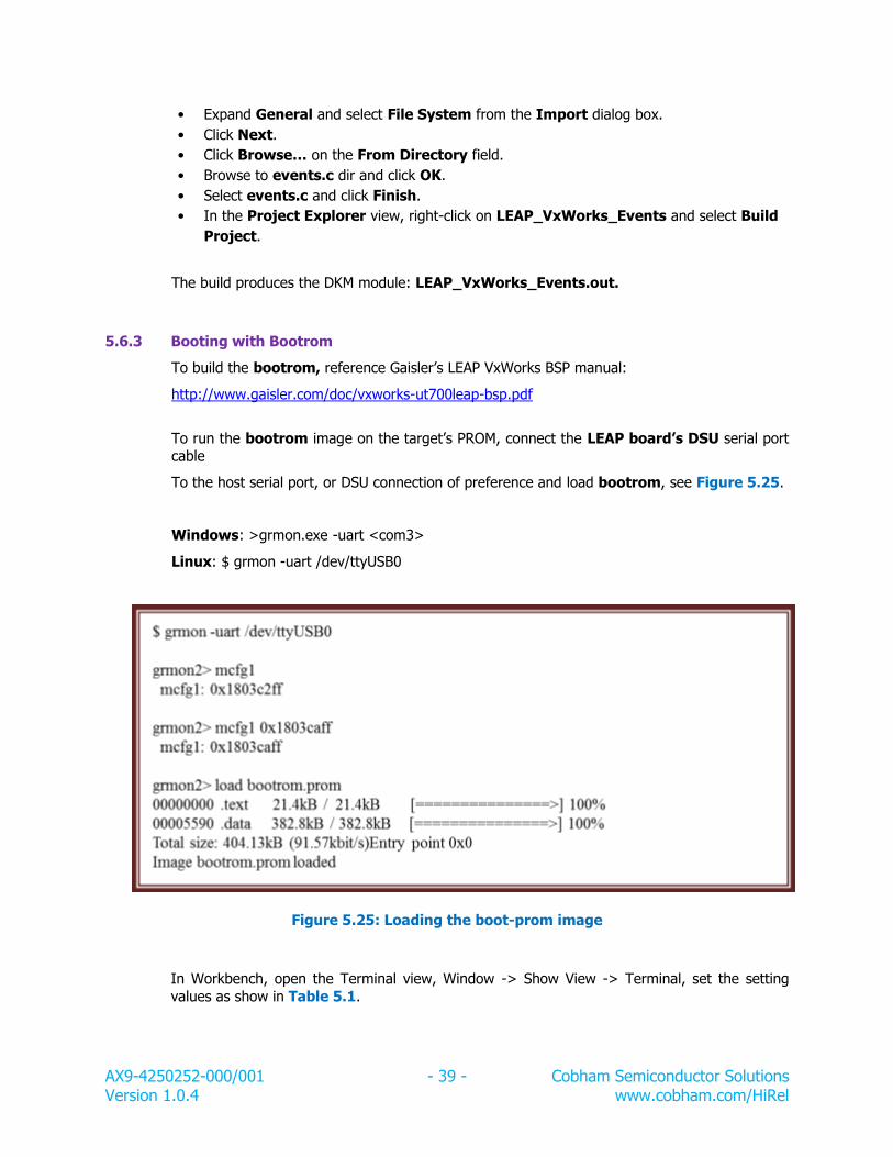
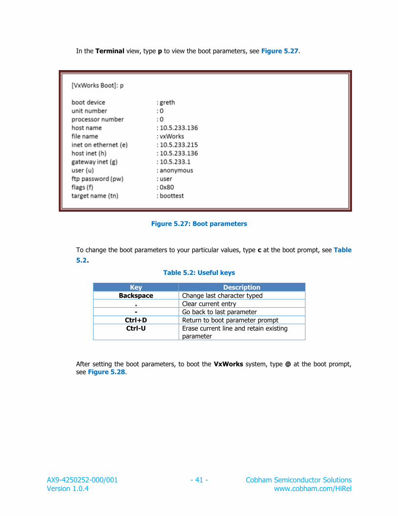
5.6 VxWorks
The VxWorks BSP contains a set of drivers for the SpaceWire core in the LEON3 SOC design. The operation of the driver is described in the VxWorks-drivers manual. The supported
hardware is summarized in the list below. For documentation about a specific core’s driver please see the LEON VxWorks Driver Manual.
Cobham Gaisler provides a SPARC/LEON architectural port for VxWorks and a UT700 BSP. The
BSP contains drivers for all UT700 peripherals. Refer to http://www.gaisler.com/ for more information.
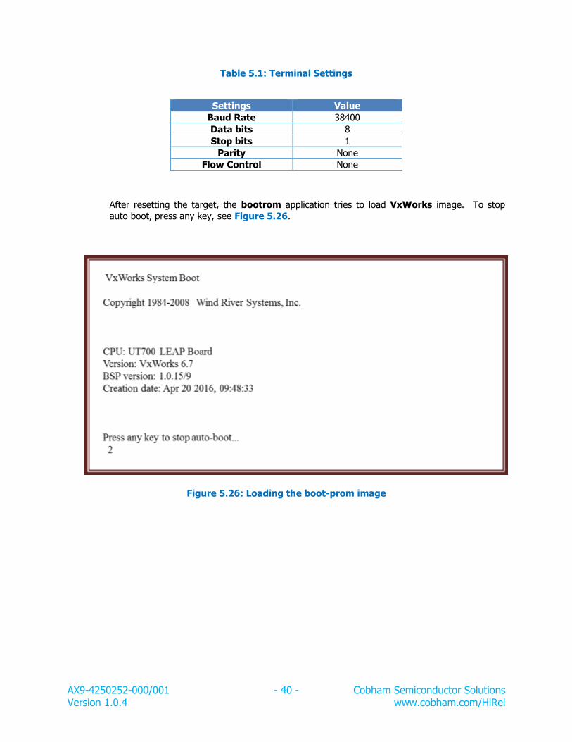
5.6.1 VxWorks Kernel
VxWorks kernel is configured by default with the target server, auto-memory configurations
and some basic features. To add more components, use the project tool in Workbench.
To Start Workbench, double-click on the Workbench icon on the desktop. From the File
menu select New -> VxWorks Image Project. Specify the project name as
AX9-4250252-000/001 - 43 - Cobham Semiconductor Solutions Version 1.0.4 www.cobham.com/HiRel
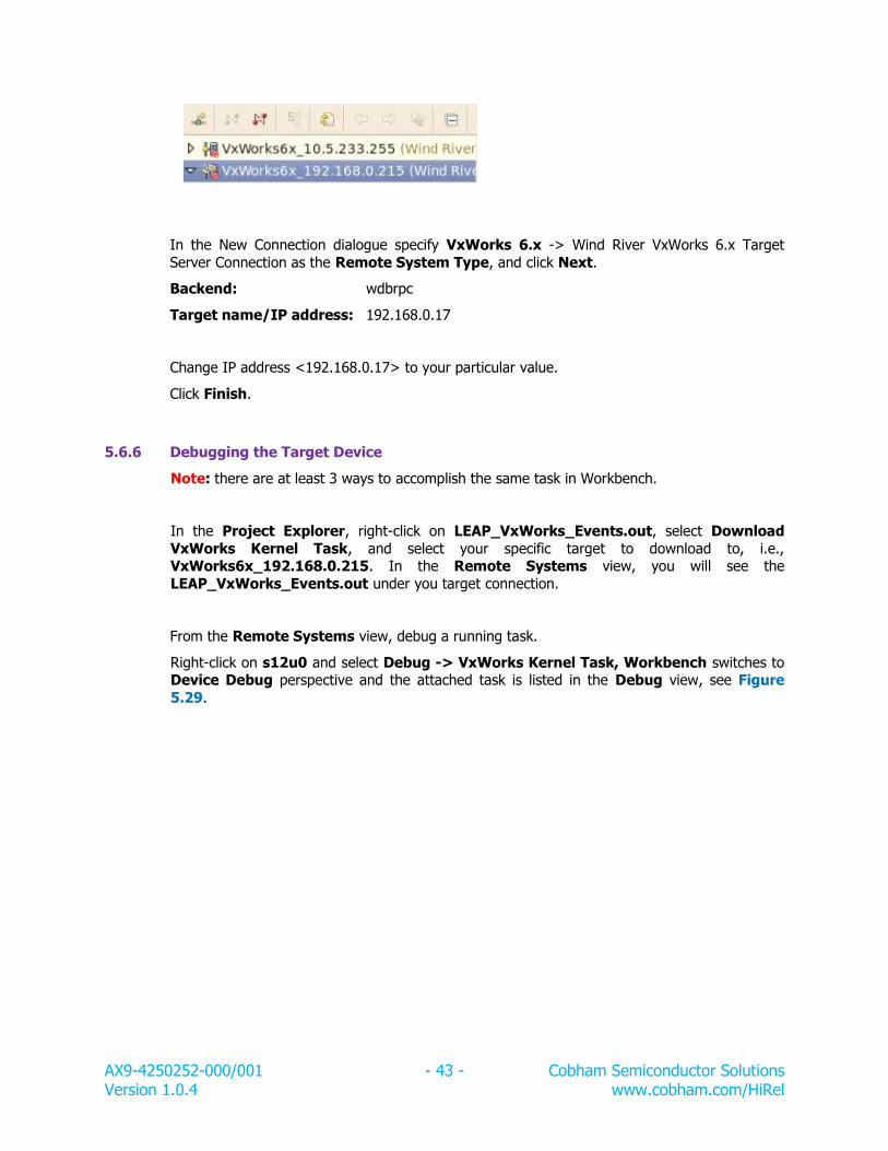
In the New Connection dialogue specify VxWorks 6.x -> Wind River VxWorks 6.x Target
Server Connection as the Remote System Type, and click Next.
Backend: wdbrpc
Target name/IP address: 192.168.0.17
Change IP address <192.168.0.17> to your particular value.
Click Finish.
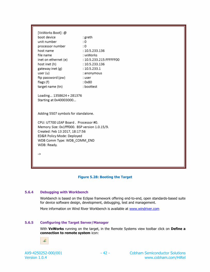
5.6.6 Debugging the Target Device
Note: there are at least 3 ways to accomplish the same task in Workbench.
In the Project Explorer, right-click on LEAP_VxWorks_Events.out, select Download
VxWorks Kernel Task, and select your specific target to download to, i.e., VxWorks6x_192.168.0.215. In the Remote Systems view, you will see the
LEAP_VxWorks_Events.out under you target connection.
From the Remote Systems view, debug a running task.
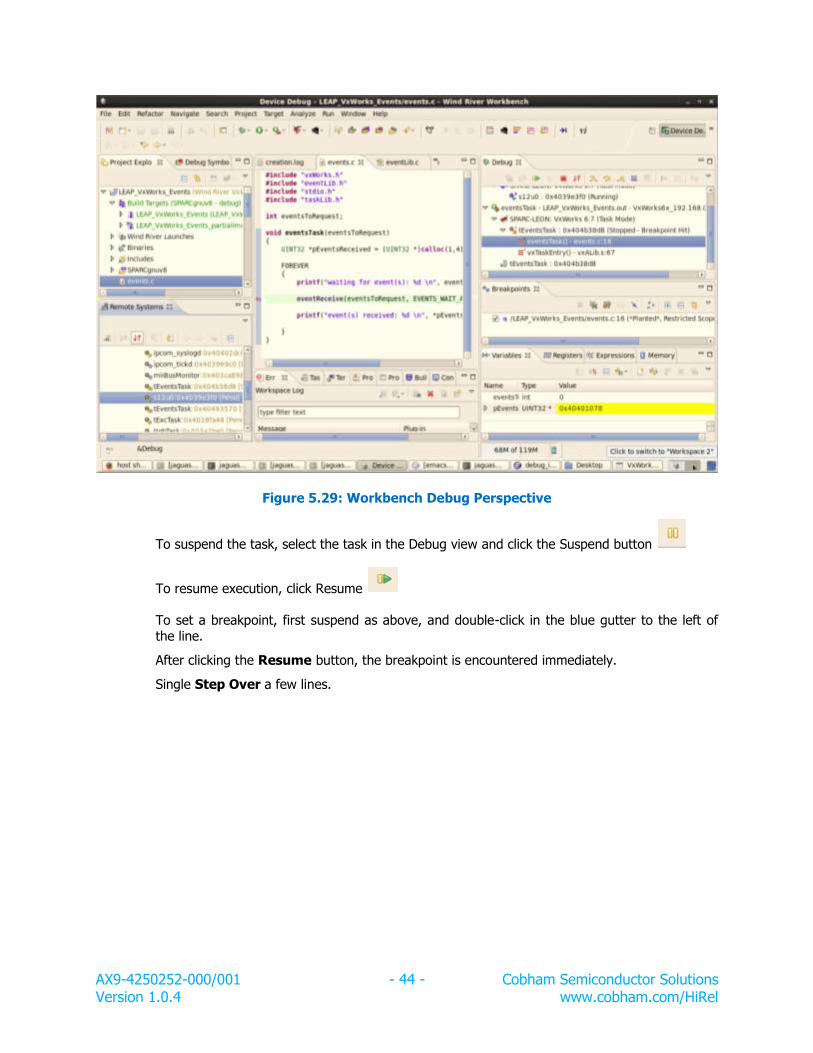
Right-click on s12u0 and select Debug -> VxWorks Kernel Task, Workbench switches to Device Debug perspective and the attached task is listed in the Debug view, see Figure
5.29.
AX9-4250252-000/001 - 44 - Cobham Semiconductor Solutions Version 1.0.4 www.cobham.com/HiRel
Figure 5.29: Workbench Debug Perspective
To suspend the task, select the task in the Debug view and click the Suspend button
To resume execution, click Resume
To set a breakpoint, first suspend as above, and double-click in the blue gutter to the left of the line.
After clicking the Resume button, the breakpoint is encountered immediately.
Single Step Over a few lines.
AX9-4250252-000/001 - 45 - Cobham Semiconductor Solutions Version 1.0.4 www.cobham.com/HiRel
5.7 Linux
Linux is a full source package, containing kernel, libraries and application code for rapid development of embedded Linux systems. The LEON port of Linux on the LEAP systems
supports the MMU configuration, V8 mul/div instructions and the floating-point unit (FPU). Below is a list of supported hardware:
LEON3 with MMU, FPU, MUL/DIV
GPTIMER System Clock Timer
IRQMP interrupt controller
APBUART system console
GRSPW SpaceWire
GRETH 10/100 and 10/100/1000 Network driver using the MDIO layer
GRPCI Host support
OCCAN implements the Linux socket CAN 2.0b interface
GRGPIO supports the generic General Purpose I/O model of Linux
SPICTRL supports SPI master interface through the spi-fsl driver
5.7.1 Linux Embedded System
Cobham Gaisler provides the LINUXBUILD utility as a quick way of getting started with Linux
development for the LEON architecture. It ties different components together to build a
complete Linux environment. Settings for standard LEON Linux configurations are available within the LINUXBUILD package and custom configurations can also be created by the
user.
The LINUXBUILD utility documentation is available at http://gaisler.com/doc/linuxbuild.pdf
AX9-4250252-000/001 - 46 - Cobham Semiconductor Solutions Version 1.0.4 www.cobham.com/HiRel
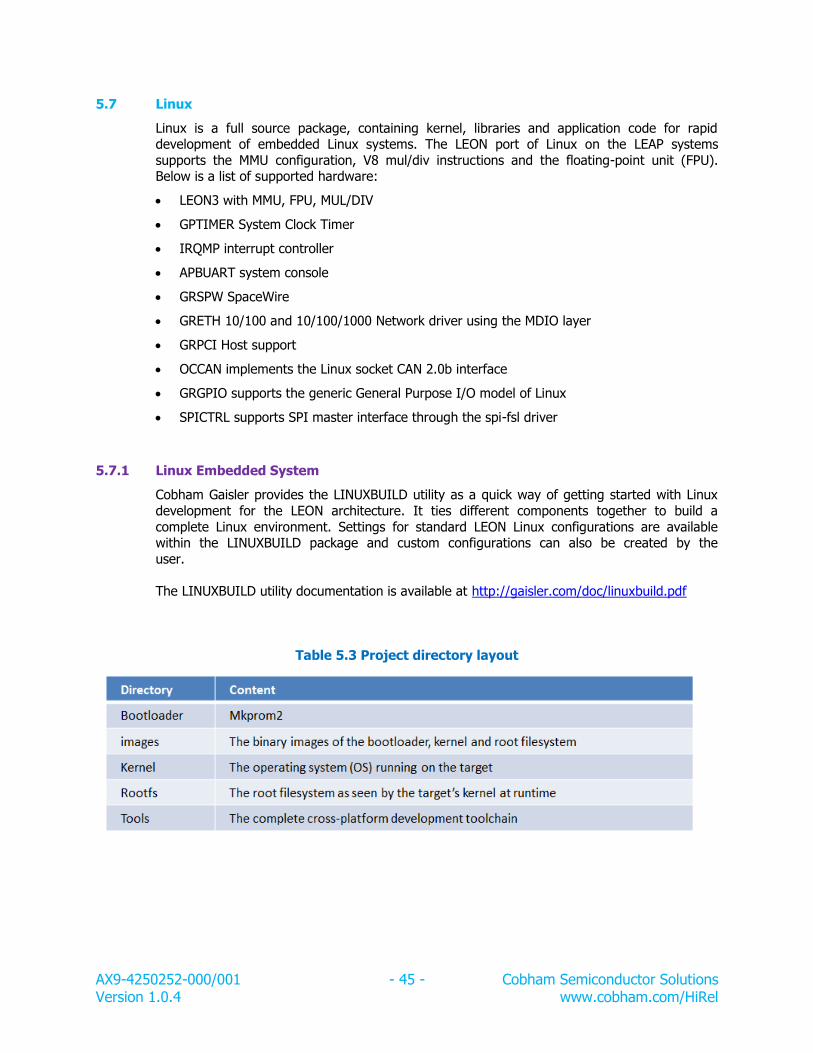
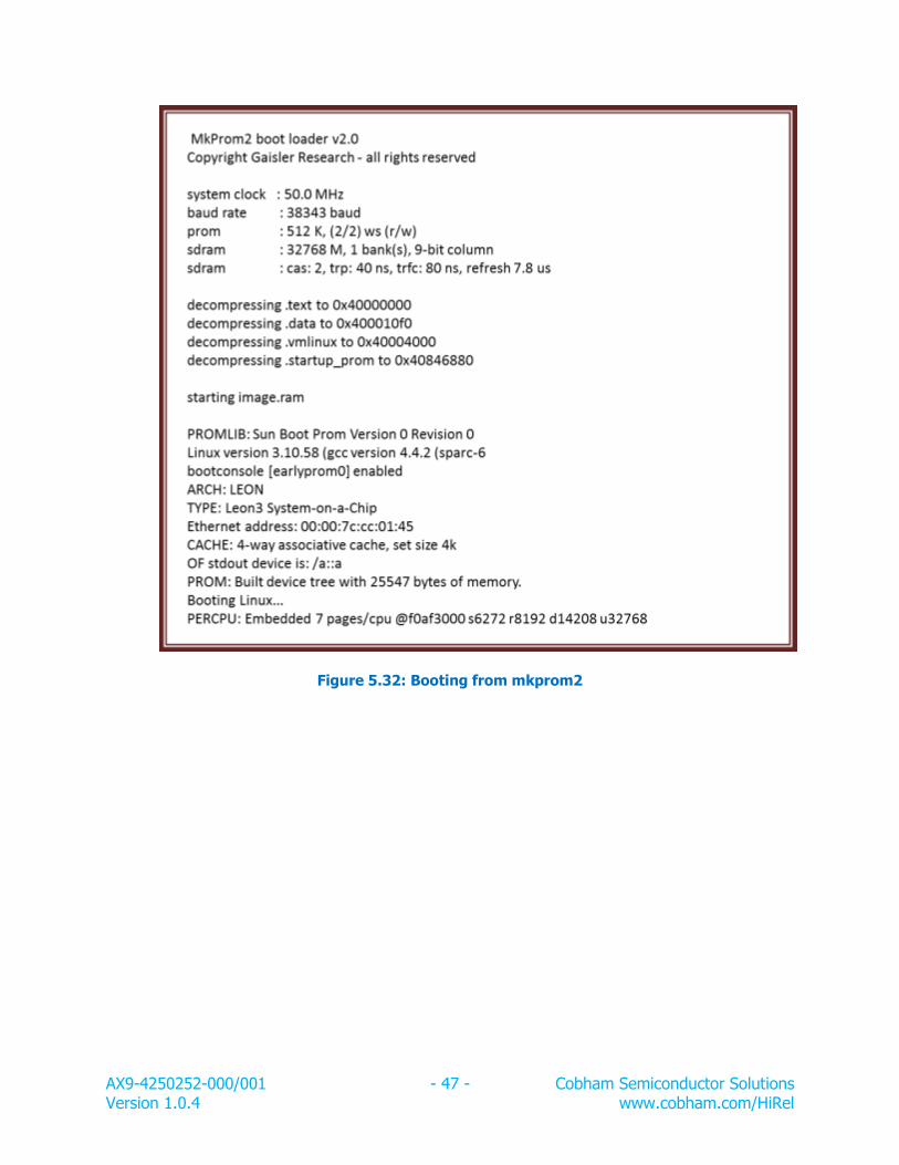
5.7.2 Booting Linux with mkprom2
Once the Linux image, image.ram, is created from LINUXBUILD, mkprom2 can create a boot-image to run from PROM on the LEON3 processor.
To generate a boot-prom from image.ram, use the following options as in Figure 5.30. Change mkprom2’s options according to the particular hardware settings.
Figure 5.30: Mkprom2 options
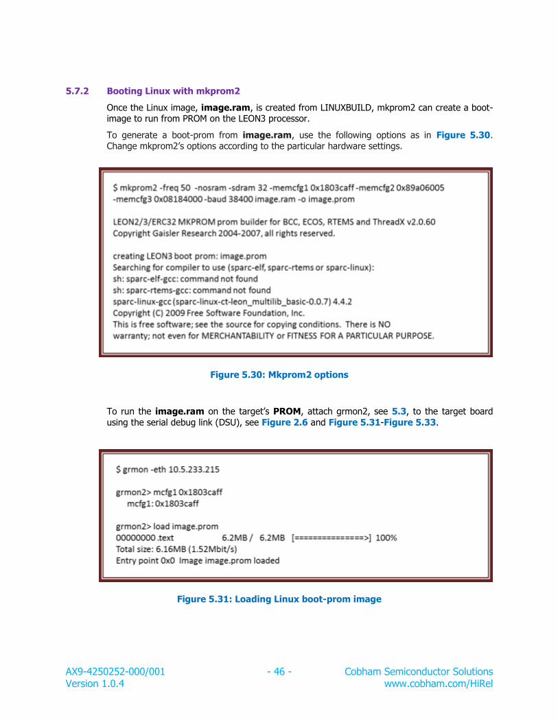
To run the image.ram on the target’s PROM, attach grmon2, see 5.3, to the target board
using the serial debug link (DSU), see Figure 2.6 and Figure 5.31-Figure 5.33.
Figure 5.31: Loading Linux boot-prom image
AX9-4250252-000/001 - 47 - Cobham Semiconductor Solutions Version 1.0.4 www.cobham.com/HiRel
Figure 5.32: Booting from mkprom2
AX9-4250252-000/001 - 48 - Cobham Semiconductor Solutions Version 1.0.4 www.cobham.com/HiRel
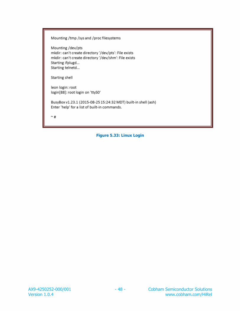
Figure 5.33: Linux Login
AX9-4250252-000/001 - 49 - Cobham Semiconductor Solutions Version 1.0.4 www.cobham.com/HiRel
Chapter 6: Benchmarks
Cobham provides a Benchmark Performance White Paper of the following benchmarks:
Dhrystones Benchmark
Coremark Benchmark
Flops20 Benchmark
Stanford Benchmark
Whetstone Benchmark
The benchmark plots and results are shown in the white paper, http://ams.aeroflex.com/pagesproduct/appnotes/ApNote_LEON_Benchmark_Performance_UT699E-