30
27 - 2013.06 / k This manual is to be given to the end user VARMECA 30 Installation and maintenance Variable speed motor or geared motor 3776 en en
| Date post: | 19-Mar-2018 |
| Category: |
Documents |
| Upload: | truongtuyen |
| View: | 216 times |
| Download: | 2 times |
27 - 2013.06 / k
This manual is to be given to
the end user
VARMECA 30
Installation and maintenanceVariable speed motor or geared motor
3776 en
en

2
2013.06 / kLEROY-SOMER InstallatIon anD maIntenance
VARMECA 30Variable speed motor or geared motor
3776 en -
NOTE
leRoY-someR reserves the right to modify the characteristics of its products at any time in order to incorporate the latest technological developments. the information contained in this document may therefore be changed without notice.
CAUTION
For the user’s own safety, this VaRmeca 30 motor must be connected to an approved earth ( terminal).If accidentally starting the installation is likely to cause a risk to personnel or the machines being driven, it is essential to supply the equipment via a circuit-breaking device (power contactor) which can be controlled via an external safety system (emergency stop, detection of errors on the installation).
the VaRmeca 30 motor is fitted with safety devices which, in the event of a fault, control stopping and thus stop the motor. the motor itself can become jammed for mechanical reasons. Voltage fluctuations, and in particular power cuts, may also cause the motor to stop. the removal of the causes of the shutdown can lead to restarting, which may be dangerous for certain machines or installations.In such cases, it is essential that the user takes appropriate precautions against the motor restarting after an unscheduled stop.the variable speed drive is designed to be able to supply a motor and the driven machine above its rated speed.If the motor or the machine are not mechanically designed to withstand such speeds, the user may be exposed to serious danger resulting from their mechanical deterioration. It is important that the user checks that the installation can withstand it, before programming a high speed.the variable speed drive which is the subject of this manual is designed to be integrated in an installation or an electrical machine, and can under no circumstances be considered to be a safety device. It is therefore the responsibility of the machine manufacturer, the designer of the installation or the user to take all necessary precautions to ensure that the system complies with current standards, and to provide any devices required to ensure the safety of equipment and personnel.
leRoY-someR declines all responsibility in the event of the above recommendations not being observed.

3
2013.06 / kLEROY-SOMER
en
InstallatIon anD maIntenance
VARMECA 30Variable speed motor or geared motor
3776 en -
• Throughout the manual, this symbol warns of consequences which may arise from inappropriate
use of the VARMECA 30, since electrical risks may lead to material or physical damage as well as constituting a fire hazard.
1 - GeneralDepending on their degree of protection, VaRmeca 30 motors may contain moving parts, as well as hot surfaces, during operation.Unjustified removal of protection devices, incorrect use, faulty installation or inappropriate operation could represent a serious risk to personnel and equipment.For further information, consult the manual.all work relating to transportation, installation, commissioning and maintenance must be performed by experienced, qualified personnel (see Iec 364 or cenelec HD 384, or DIn VDe 0100 and national specifications for installation and accident prevention).In these basic safety instructions, qualified personnel means persons competent to install, mount, commission and operate the product and possessing the relevant qualifications.
2 - UseVaRmeca 30 motors are components designed for integration in installations or electrical machines.When integrated in a machine, commissioning must not take place until it has been verified that the machine conforms with directive 2006/42/ec (machinery Directive).It is also necessary to comply with standard en 60204, which stipulates in particular that electrical actuators (which include VaRmeca 30) cannot be regarded as circuit-breaking devices and certainly not as isolating switches.commissioning can take place only if the requirements of the electromagnetic compatibility Directive (emc 2004/108/ec) are met.VaRmeca 30 motors meet the requirements of the low Voltage Directive 2006/95/ec. the harmonised standard of the DIn VDe 0160 series in connection with standard VDe 0660, part 500 and en 60146/VDe 0558 are also applicable.the technical characteristics and instructions concerning the connection conditions specified on the nameplate and in the documentation provided must be observed without fail.
3 - Transportation, storageall instructions concerning transportation, storage and correct handling must be observed.the climatic conditions specified in the technical manual must be observed.
4 - Installationthe installation and cooling of equipment must comply with the specifications in the manual supplied with the product.VaRmeca 30 motors must be protected against excessive stress. In particular, there must be no damage to parts and/or modification of the clearance between components during transportation and handling. avoid touching the electronic components and contact parts.VaRmeca 30 motors contain parts which are sensitive to electrostatic stress and may be easily damaged if handled incorrectly. electrical components must not be exposed to mechanical damage or destruction (risks to health!).
5 - Electrical connectionWhen work is performed on VaRmeca 30 motors which are powered up, national accident prevention specifications must be respected.the electrical installation must comply with the relevant specifications (for example conductor cross-sections, protection via fused circuit-breaker, connection of protective conductor). more detailed information is given in the manual.Instructions for an installation which meets the requirements for electromagnetic compatibility, such as screening, earthing, presence of filters and correct insertion of cables and conductors, are given in the documentation supplied with the VaRmeca 30. these instructions must be followed in all cases, even if the VaRmeca 30 carries the ce mark. adherence to the limits given in the emc legislation is the responsibility of the manufacturer of the installation or the machine.
6 - OperationInstallations incorporating VaRmeca 30 motors must be fitted with additional protection and monitoring devices as laid down in the current relevant safety regulations: law on technical equipment, accident prevention regulations, etc. modification of VaRmeca 30 motors using control software is permitted.active parts of the device and live power connections must not be touched immediately after the VaRmeca 30 is powered down, as the capacitors may still be charged. In view of this, the warnings fixed to VaRmeca 30 motors must be observed.During operation, all protective covers must remain closed.
7 - Servicing and maintenanceRefer to the manufacturer’s documentation.
SAFETY AND OPERATING INSTRUCTIONS FOR ELECTRICAL ACTUATORS (In accordance with the low voltage directive 2006/95/EC)

4
2013.06 / kLEROY-SOMER InstallatIon anD maIntenance
VARMECA 30Variable speed motor or geared motor
3776 en -
NOTES
5
2013.06 / kLEROY-SOMER
en
InstallatIon anD maIntenance
VARMECA 30Variable speed motor or geared motor
3776 en -
CONTENTS
1 - GENERAL INFORMATION ................................................................................................................................. 61.1 - General operating principle ................................................................................................................................ 61.2 - Product name.................................................................................................................................................... 61.3 - characteristics .................................................................................................................................................. 71.4 - environmental characteristics ........................................................................................................................... 91.5 - Radio-frequency interference............................................................................................................................ 91.6 - Description of cables and protection devices .................................................................................................. 121.7 - operating ranges according to the switching frequency .................................................................................. 131.8 - Ul conformity .................................................................................................................................................. 131.9 - Weights and dimensions ................................................................................................................................. 14
2 - INSTALLATION ................................................................................................................................................. 152.1 - General ........................................................................................................................................................... 15
3 - CONNECTIONS ................................................................................................................................................ 153.1 - Wiring precautions .......................................................................................................................................... 153.2 - control terminal blocks.................................................................................................................................... 163.3 - Power terminal blocks ..................................................................................................................................... 183.4 - terminal blocks for options .............................................................................................................................. 183.5 - Wiring diagrams .............................................................................................................................................. 193.6 - Power supply and control for FcR brake motors ............................................................................................. 223.7 - example of supplying 2 motors, with or without brake, in parallel, with a single VaRmeca ............................. 223.8 - Wiring diagrams for esFR Vma ...................................................................................................................... 23
4 - COMMISSIONING ............................................................................................................................................. 254.1 - starting with the power supply......................................................................................................................... 254.2 - starting with remote volt-free contact .............................................................................................................. 254.3 - starting with local run/stop control (Bma 31/32, Bma 33/34 or BmaVaR 31/32,
BmaVaR 33/34 option) ................................................................................................................................... 254.4 - setting the speed ............................................................................................................................................ 25
5 - FAULTS-DIAGNOSTICS ................................................................................................................................... 26
6 - MAINTENANCE ................................................................................................................................................ 266.1 - care ................................................................................................................................................................ 266.2 - measurements ................................................................................................................................................ 26
7 - OPTIONS ........................................................................................................................................................... 277.1 - speed control knob (B 31/32 or B 33/34) ......................................................................................................... 277.2 - control knob with integrated run-stop control (Bma31/32 or Bma 33/34) ........................................................ 277.3 - control knob with forward/reverse/stop control (BmaVaR 31/32 or BmaVaR 33/34) ...................................... 277.4 - Internal speed control (cVI Vma 31/32 or cVI Vma 33/34) ............................................................................. 277.5 - IP 20 braking resistor (RF100 – RF 200 – RF 600) .......................................................................................... 287.6 - IP 20 external braking resistor (RF – BRR – 800 – 200) .................................................................................. 287.7 - Power supply and sequential brake control option (esFR Vma 31/32) ........................................................... 287.8 - Power supply and sequential brake control option (esFR Vma 33/34) ........................................................... 287.9 - Fieldbus (Vma 33/34)...................................................................................................................................... 287.10 - encoder feedback (coD Vma 33/34)............................................................................................................ 287.11 - Parameter-setting console (PX lcD) ............................................................................................................ 297.12 - Parameter-setting software (Vma soFt)...................................................................................................... 297.13 - operator display (PaD Vma 30) .................................................................................................................... 297.14 - XPress Key (PX Key) .................................................................................................................................... 297.15 - emc filter for Vma 33/34 ............................................................................................................................... 307.16 - emc filter for Vma 31m/32m ......................................................................................................................... 307.17 - emc filter for Vma31t/32t ........................................................................................................................... 30
6
2013.06 / kLEROY-SOMER InstallatIon anD maIntenance
VARMECA 30Variable speed motor or geared motor
3776 en -
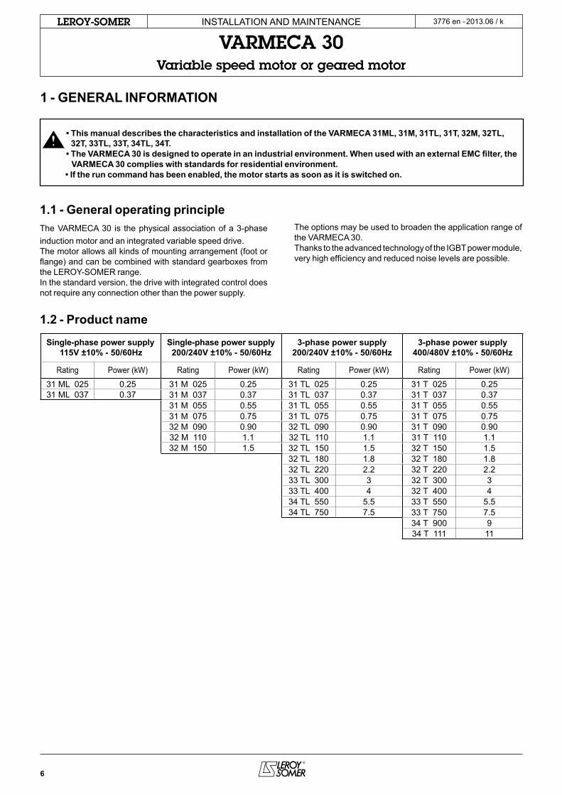
• This manual describes the characteristics and installation of the VARMECA 31ML, 31M, 31TL, 31T, 32M, 32TL, 32T, 33TL, 33T, 34TL, 34T.
• The VARMECA 30 is designed to operate in an industrial environment. When used with an external EMC filter, the VARMECA 30 complies with standards for residential environment.
• If the run command has been enabled, the motor starts as soon as it is switched on.
1 - GENERAL INFORMATION
1.2 - Product name
Single-phase power supply115V ±10% - 50/60Hz
Single-phase power supply200/240V ±10% - 50/60Hz
3-phase power supply200/240V ±10% - 50/60Hz
3-phase power supply400/480V ±10% - 50/60Hz
Rating Power (kW) Rating Power (kW) Rating Power (kW) Rating Power (kW)
31 ml 025 0.25 31 m 025 0.25 31 tl 025 0.25 31 t 025 0.2531 ml 037 0.37 31 m 037 0.37 31 tl 037 0.37 31 t 037 0.37
31 m 055 0.55 31 tl 055 0.55 31 t 055 0.5531 m 075 0.75 31 tl 075 0.75 31 t 075 0.7532 m 090 0.90 32 tl 090 0.90 31 t 090 0.9032 m 110 1.1 32 tl 110 1.1 31 t 110 1.132 m 150 1.5 32 tl 150 1.5 32 t 150 1.5
32 tl 180 1.8 32 t 180 1.832 tl 220 2.2 32 t 220 2.233 tl 300 3 32 t 300 333 tl 400 4 32 t 400 434 tl 550 5.5 33 t 550 5.534 tl 750 7.5 33 t 750 7.5
34 t 900 934 t 111 11
1.1 - General operating principlethe VaRmeca 30 is the physical association of a 3-phase induction motor and an integrated variable speed drive.the motor allows all kinds of mounting arrangement (foot or flange) and can be combined with standard gearboxes from the leRoY-someR range.In the standard version, the drive with integrated control does not require any connection other than the power supply.
the options may be used to broaden the application range of the VaRmeca 30.thanks to the advanced technology of the IGBt power module, very high efficiency and reduced noise levels are possible.
7
2013.06 / kLEROY-SOMER
en
InstallatIon anD maIntenance
VARMECA 30Variable speed motor or geared motor
3776 en -
OPERATING EXTENSIONS
Designation DescriptionB 31/32 or B 33/34 Integrated speed control knobBma 31/32 or Bma 33/34 speed control knob and integrated run-stop control knobBmaVaR 31/32 or BmaVaR 33/34 speed control knob and integrated stop forward/reverse control knobcVI Vma 31/32 or cVI Vma 33/34 Integrated speed controlesFR Vma 31/32 or esFR Vma 33/34 Brake controlRF100 – RF200 – RF600 Braking resistor Power 100, 200 and 600 WRF – BRR – 800 – 200 Braking resistor Power 800 W – external mountingPX lcD Parameter-setting consolecoD Vma 33/34 encoder feedbackVma soFt Parameter-setting softwarePaD Vma 31/32 or PaD Vma 33/34 local display unitPX KeY copy keyVma com PB 33/34 Fieldbus: PRoFIBUs DPVma com Is 33/34 Fieldbus: InteRBUs sVma com Dt 33/34 Fieldbus: DeVIcenetVma com cn 33/34 Fieldbus: can oPenFlt Vma 31-32m 110/Flt Vma 32m 150 emc filter for residential environment – Filter for the single phase rangeFlt Vma 31/32t 220/Flt Vma 32t 400 emc filter for residential environment – Filter for the Vma 31/32 three phase rangeFlt Vma 33 emc filter for industrial environment – mounting for Vma 33 tl/tFlt Vma 34 emc filter for industrial environment – mounting for Vma 34 tl/t
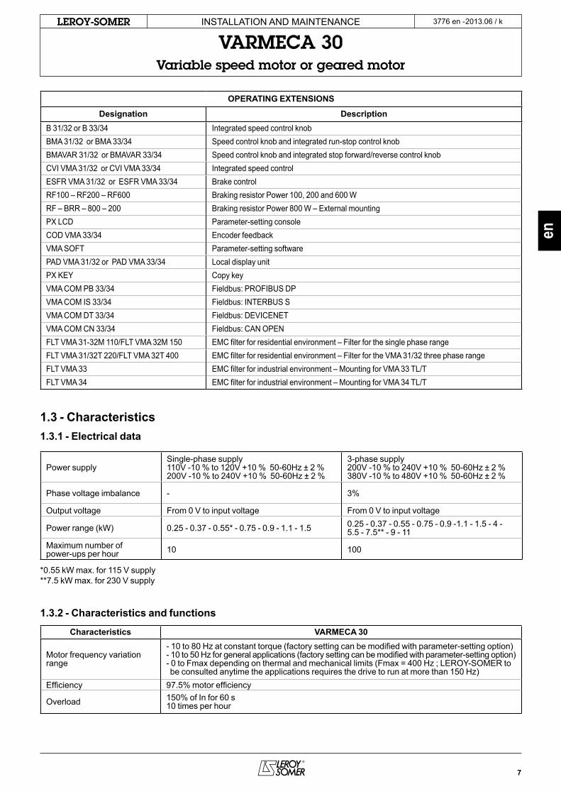
1.3 - Characteristics1.3.1 - Electrical data
Power supplysingle-phase supply110V -10 % to 120V +10 % 50-60Hz ± 2 %200V -10 % to 240V +10 % 50-60Hz ± 2 %
3-phase supply 200V -10 % to 240V +10 % 50-60Hz ± 2 %380V -10 % to 480V +10 % 50-60Hz ± 2 %
Phase voltage imbalance - 3%
output voltage From 0 V to input voltage From 0 V to input voltage
Power range (kW) 0.25 - 0.37 - 0.55* - 0.75 - 0.9 - 1.1 - 1.5 0.25 - 0.37 - 0.55 - 0.75 - 0.9 -1.1 - 1.5 - 4 -5.5 - 7.5** - 9 - 11
maximum number of power-ups per hour 10 100
*0.55 kW max. for 115 V supply**7.5 kW max. for 230 V supply
1.3.2 - Characteristics and functions
Characteristics VARMECA 30
motor frequency variation range
- 10 to 80 Hz at constant torque (factory setting can be modified with parameter-setting option)- 10 to 50 Hz for general applications (factory setting can be modified with parameter-setting option)- 0 to Fmax depending on thermal and mechanical limits (Fmax = 400 Hz ; leRoY-someR to be consulted anytime the applications requires the drive to run at more than 150 Hz)
efficiency 97.5% motor efficiency
overload 150% of In for 60 s10 times per hour

8
2013.06 / kLEROY-SOMER InstallatIon anD maIntenance
VARMECA 30Variable speed motor or geared motor
3776 en -
Pilot control VARMECA 30
speed reference
- analogue reference (0 V or 4 ma) = minimum speed (10 V or 20 ma) = maximum speed- 0 to 10 V with integrated potentiometer (B31/32 – B33/34 option)- 0 to 10 V with remote potentiometer- 4 to 20 ma with external reference- Reference with internal potentiometer- Digital references- Fieldbus
speed regulation - speed regulation with encoder feedback option for Vma 33 or 34 only- Regulation of a reference with integrated PI loop
Run/stop- With power supply- With remote volt-free contact- With fieldbus- With local run/stop control
Forward/Reverse- With internal connection on the terminal block- With remote volt-free contact- With fieldbus- With local run/stop control
stop mode- on ramps (using volt-free contact or integrated control)- Freewheel- With electromechanical brake
Ramps - Ramps adjustable from 0 to 600s
Fieldbus - PRoFIBUs DP, InteRBUs s, DeVIcenet, can oPen, moDBUs RtU, ls net
Protection VARMECA 30
Power
- Undervoltage (see notice 3847)- overvoltage (see notice 3847)- overloads (see notice 3847) .thermal, drive and motor .protection against locked rotor- short-circuit .motor windings- overspeed (see notice 3847)
control - short-circuit on 0-10 V/24 V inputs or outputs
Drive reset - By switching off the VaRmeca 30 or by opening/closing the connection between the 24V and ena (Vma 31/32) terminals or sDI 1 and sDI 2 (Vma 33/34) terminals
9
2013.06 / kLEROY-SOMER
en
InstallatIon anD maIntenance
VARMECA 30Variable speed motor or geared motor
3776 en -
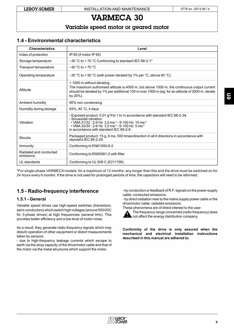
1.4 - Environmental characteristicsCharacteristics Level
Index of protection IP 65 (if motor IP 65)
storage temperature - 40 °c to + 70 °c conforming to standard Iec 68-2-1*
transport temperature - 40 °c to + 70 °c
operating temperature - 20 °c to + 50 °c (with power derated by 1% per °c, above 40 °c)
altitude
< 1000 m without derating.the maximum authorised altitude is 4000 m, but above 1000 m, the continuous output current should be derated by 1% per additional 100 m over 1000 m (eg: for an altitude of 3000 m, derate by 20%).
ambient humidity 95% non condensing
Humidity during storage 93%, 40 °c, 4 days
Vibration
- exposed product: 0.01 g2/Hz 1 hr in accordance with standard Iec 68-2-34.- sinusoidal vibration: • Vma 31/32 : 2-9 Hz 3,5 ms-2 - 9-100 Hz 10 ms-2
• Vma 33/34 : 2-6 Hz 3,5 ms-2 - 6-100 Hz 5 ms-2
in accordance with standard Iec 68-2-6.
shocks Packaged product: 15 g, 6 ms, 500 times/direction in all 6 directions in accordance with standard Iec 68-2-29.
Immunity conforming to en61000-6-2
Radiated and conducted emissions conforming to en50081-2 with filter
Ul standards conforming to Ul 508 c (e211799)
*For single-phase VaRmeca models: for a maximum of 12 months; any longer than this and the drive must be switched on for 24 hours every 6 months. If the drive is not used for prolonged periods of time, the capacitors will need to be reformed.
1.5 - Radio-frequency interference1.5.1 - GeneralVariable speed drives use high-speed switches (transistors, semi-conductors) which switch high voltages (around 550VDc for 3-phase drives) at high frequencies (several kHz). this provides better efficiency and a low level of motor noise.
as a result, they generate radio-frequency signals which may disturb operation of other equipment or distort measurements taken by sensors:- due to high-frequency leakage currents which escape to earth via the stray capacity of the drive/motor cable and that of the motor via the metal structures which support the motor.
- by conduction or feedback of R.F. signals on the power supply cable: conducted emissions.- by direct radiation near to the mains supply power cable or the drive/motor cable: radiated emissions.these phenomena are of direct interest to the user.
the frequency range concerned (radio frequency) does not affect the energy distribution company.
Conformity of the drive is only assured when the mechanical and electrical installation instructions described in this manual are adhered to.

10
2013.06 / kLEROY-SOMER InstallatIon anD maIntenance
VARMECA 30Variable speed motor or geared motor
3776 en -
1.5.2 - Standards (Emission)the maximum emission level is set by the generic industrial (en 61000-6-4) and residential (en 61000-6-3) standards.VaRmeca 30 conforms to the following standards:en 61000-6-4 (en 50081-2), en 61000-6-3 (en 50081-1), en 61800-3 (ceI 61800-3).
Standard Description Application Standard driveWith EMC filter option
LEROY-SOMERInternal mounting External mounting
en 61800-3(ceI 61800-3)
Variable speed drive standards
second environment with
unrestricted distribution
(DenR)
Vma31m/32m ≤ 4 KHzVma31t/32t ≤ 4 KHz
Vma33t/34t ≤ 4.5 KHz- -
second environment with
restricted distribution (DeR)
Vma31m/32m ≤ 4 KHzVma31t/32t ≤ 4 KHz
Vma33t/34t ≤ 4.5 KHz- -
First environment with unrestricted distribution (R)
- Vma31m ≤ 4 KHzVma32m* ≤ 4 KHz
Vma32m** ≤ 4 KHzVma31t/32t ≤ 4 KHz
First environment with restricted distribution (I)
Vma31t/32t ≤ 4 KHzVma31m ≤ 4 KHzVma32m* ≤ 4 KHz
Vma33t/34t ≤ 4.5 KHzVma32m** ≤ 4 KHz
en 61000-6-3(en 50081-1)
Generic emission standards
for residential, commercial and light industrial environments
a.c. supply - Vma31m ≤ 4 KHzVma32m* ≤ 4 KHz
Vma32m** ≤ 4 KHzVma31t/32t ≤ 4 KHz
en 61000-6-4(en 50081-2)
Generic emission standards for the
industrial environmenta.c. supply Vma31t/32t ≤ 4 KHz
Vma31m ≤ 4 KHzVma32m* ≤ 4 KHz
Vma33t/34t ≤ 4.5 KHzVma32m** ≤ 4 KHz
* for power ≤ 0.9 kW** for power 1.1 kW & 1.5 kWVma 33/34t residential standard : contact tHe FactoRYRange of switching frequencies : contact tHe FactoRY
For the new en 61800-3 standard april 2005, the drive distri-bution classes (restricted and unrestricted) are replaced by the drive classes (c1 to c4) defined with respect to drives themselves and its specific application.
VARMECA motors are associated with SE categories C2 and C3, for applications category C1, contact the factory.
NOTE :se = drive system
the categories are as follows:
se category c1se for voltages less than 1000V, intended for use in the First environment.
se category c2 se for voltages less than 1000V, which are not connected by supply cable and plug, nor mobile equipment, and which, are used in the First environment, and are intended to be instal-led and put into service only by a professional (person or organisation having the necessary competence for the installation and/or commissioning of power drive sys-tems, including the aspects of EMC).
se category c3 se for voltages less than 1000V, intended for use in the se-cond environment and not for use in the First environment.
First environment :the first environment includes domestic premises. It also in-cludes establishments directly connected without intermediate transformer to a low voltage power supply network which sup-plies buildings used for domestic purposes.
second environment :the second environment includes all establishments other than those directly connected to a low voltage power supply network which supplies buildings used for domestic purposes.
11
2013.06 / kLEROY-SOMER
en
InstallatIon anD maIntenance
VARMECA 30Variable speed motor or geared motor
3776 en -
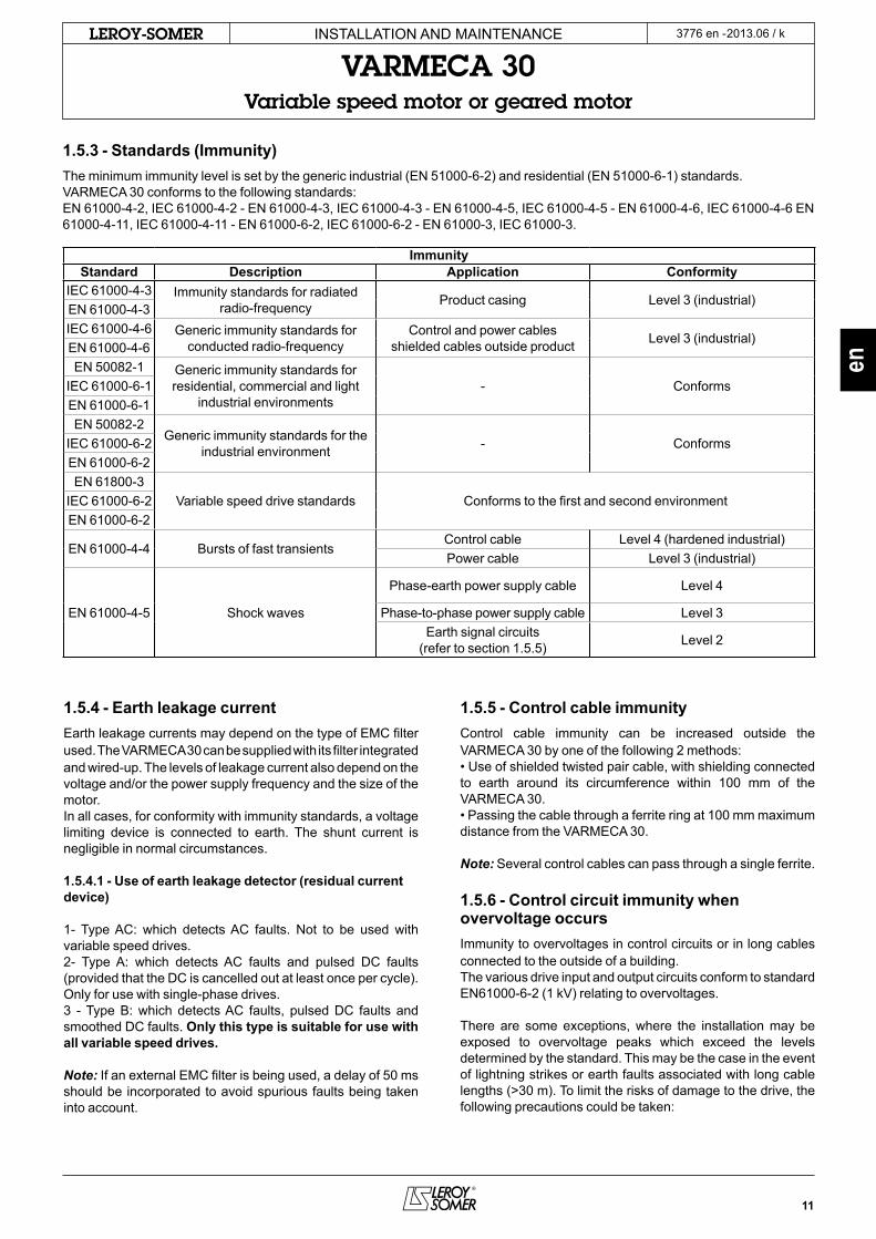
1.5.3 - Standards (Immunity)the minimum immunity level is set by the generic industrial (en 51000-6-2) and residential (en 51000-6-1) standards.VaRmeca 30 conforms to the following standards:en 61000-4-2, Iec 61000-4-2 - en 61000-4-3, Iec 61000-4-3 - en 61000-4-5, Iec 61000-4-5 - en 61000-4-6, Iec 61000-4-6 en 61000-4-11, Iec 61000-4-11 - en 61000-6-2, Iec 61000-6-2 - en 61000-3, Iec 61000-3.
ImmunityStandard Description Application Conformity
Iec 61000-4-3 Immunity standards for radiated radio-frequency Product casing level 3 (industrial)
en 61000-4-3Iec 61000-4-6 Generic immunity standards for
conducted radio-frequencycontrol and power cables
shielded cables outside product level 3 (industrial)en 61000-4-6en 50082-1 Generic immunity standards for
residential, commercial and light industrial environments
- conformsIec 61000-6-1en 61000-6-1en 50082-2
Generic immunity standards for the industrial environment - conformsIec 61000-6-2
en 61000-6-2en 61800-3
Variable speed drive standards conforms to the first and second environmentIec 61000-6-2en 61000-6-2
en 61000-4-4 Bursts of fast transientscontrol cable level 4 (hardened industrial)Power cable level 3 (industrial)
en 61000-4-5 shock waves
Phase-earth power supply cable level 4
Phase-to-phase power supply cable level 3earth signal circuits
(refer to section 1.5.5) level 2
1.5.4 - Earth leakage currentearth leakage currents may depend on the type of emc filter used. the VaRmeca 30 can be supplied with its filter integrated and wired-up. the levels of leakage current also depend on the voltage and/or the power supply frequency and the size of the motor.In all cases, for conformity with immunity standards, a voltage limiting device is connected to earth. the shunt current is negligible in normal circumstances.
1.5.4.1 - Use of earth leakage detector (residual current device)
1- type ac: which detects ac faults. not to be used with variable speed drives.2- type a: which detects ac faults and pulsed Dc faults (provided that the Dc is cancelled out at least once per cycle). only for use with single-phase drives.3 - type B: which detects ac faults, pulsed Dc faults and smoothed Dc faults. Only this type is suitable for use with all variable speed drives.
Note: If an external emc filter is being used, a delay of 50 ms should be incorporated to avoid spurious faults being taken into account.
1.5.5 - Control cable immunitycontrol cable immunity can be increased outside the VaRmeca 30 by one of the following 2 methods: • Use of shielded twisted pair cable, with shielding connected to earth around its circumference within 100 mm of the VaRmeca 30.• Passing the cable through a ferrite ring at 100 mm maximum distance from the VaRmeca 30.
Note: several control cables can pass through a single ferrite.
1.5.6 - Control circuit immunity when overvoltage occursImmunity to overvoltages in control circuits or in long cables connected to the outside of a building.the various drive input and output circuits conform to standard en61000-6-2 (1 kV) relating to overvoltages.
there are some exceptions, where the installation may be exposed to overvoltage peaks which exceed the levels determined by the standard. this may be the case in the event of lightning strikes or earth faults associated with long cable lengths (>30 m). to limit the risks of damage to the drive, the following precautions could be taken:
12
2013.06 / kLEROY-SOMER
0V 0V
InstallatIon anD maIntenance
VARMECA 30Variable speed motor or geared motor
3776 en -
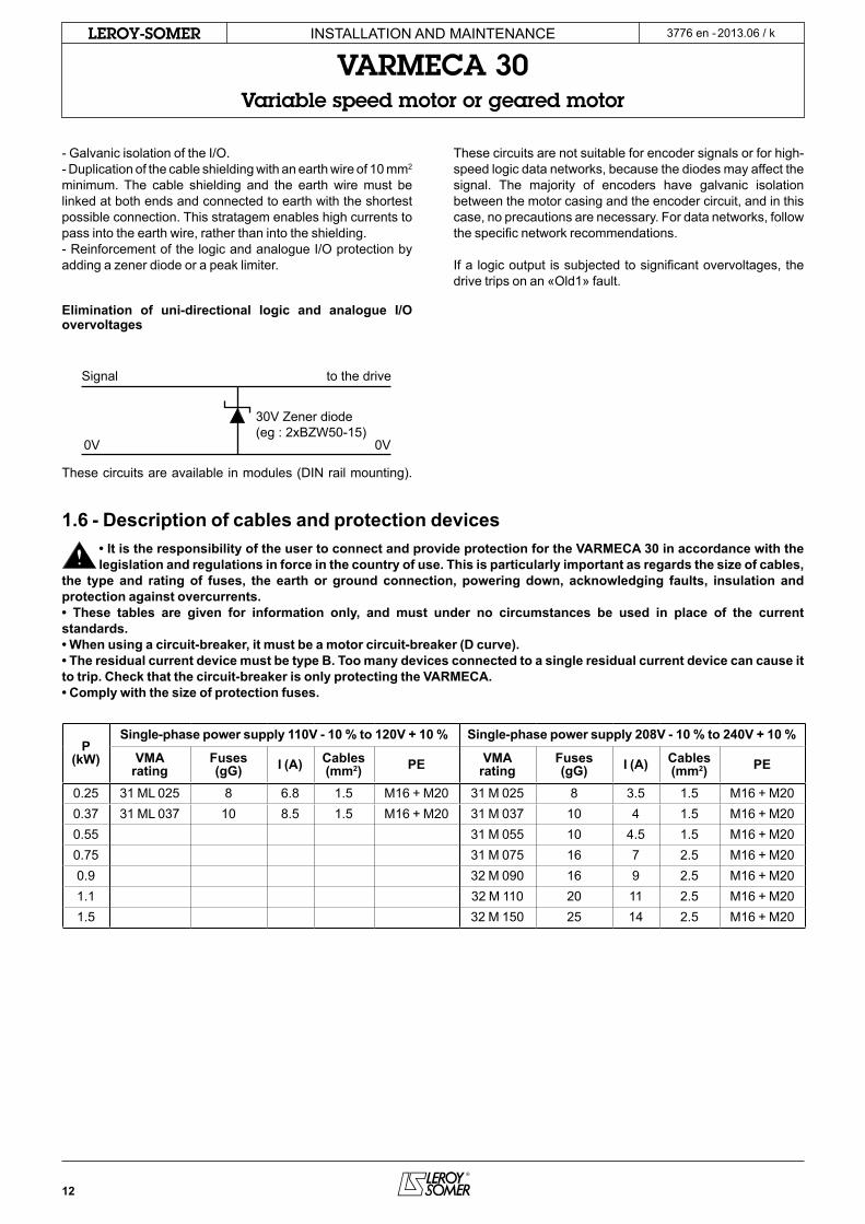
1.6 - Description of cables and protection devices• It is the responsibility of the user to connect and provide protection for the VARMECA 30 in accordance with the legislation and regulations in force in the country of use. This is particularly important as regards the size of cables,
the type and rating of fuses, the earth or ground connection, powering down, acknowledging faults, insulation and protection against overcurrents.• These tables are given for information only, and must under no circumstances be used in place of the current standards.• When using a circuit-breaker, it must be a motor circuit-breaker (D curve).• The residual current device must be type B. Too many devices connected to a single residual current device can cause it to trip. Check that the circuit-breaker is only protecting the VARMECA.• Comply with the size of protection fuses.
P (kW)
Single-phase power supply 110V - 10 % to 120V + 10 % Single-phase power supply 208V - 10 % to 240V + 10 %
VMArating
Fuses (gG) I (A) Cables
(mm2) PE VMArating
Fuses (gG) I (A) Cables
(mm2) PE
0.25 31 ml 025 8 6.8 1.5 m16 + m20 31 m 025 8 3.5 1.5 m16 + m200.37 31 ml 037 10 8.5 1.5 m16 + m20 31 m 037 10 4 1.5 m16 + m200.55 31 m 055 10 4.5 1.5 m16 + m200.75 31 m 075 16 7 2.5 m16 + m200.9 32 m 090 16 9 2.5 m16 + m201.1 32 m 110 20 11 2.5 m16 + m201.5 32 m 150 25 14 2.5 m16 + m20
- Galvanic isolation of the I/o.- Duplication of the cable shielding with an earth wire of 10 mm2 minimum. the cable shielding and the earth wire must be linked at both ends and connected to earth with the shortest possible connection. this stratagem enables high currents to pass into the earth wire, rather than into the shielding.- Reinforcement of the logic and analogue I/o protection by adding a zener diode or a peak limiter.
Elimination of uni-directional logic and analogue I/O overvoltages
these circuits are available in modules (DIn rail mounting).
these circuits are not suitable for encoder signals or for high-speed logic data networks, because the diodes may affect the signal. the majority of encoders have galvanic isolation between the motor casing and the encoder circuit, and in this case, no precautions are necessary. For data networks, follow the specific network recommendations.
If a logic output is subjected to significant overvoltages, the drive trips on an «old1» fault.
signal
30V Zener diode(eg : 2xBZW50-15)
to the drive
13
2013.06 / kLEROY-SOMER
en
InstallatIon anD maIntenance
VARMECA 30Variable speed motor or geared motor
3776 en -
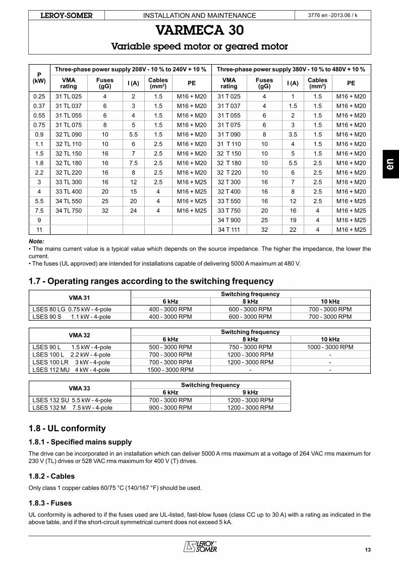
P (kW)
Three-phase power supply 208V - 10 % to 240V + 10 % Three-phase power supply 380V - 10 % to 480V + 10 %
VMA rating
Fuses (gG) I (A) Cables
(mm2) PE VMA rating
Fuses (gG) I (A) Cables
(mm2) PE
0.25 31 tl 025 4 2 1.5 m16 + m20 31 t 025 4 1 1.5 m16 + m200.37 31 tl 037 6 3 1.5 m16 + m20 31 t 037 4 1.5 1.5 m16 + m200.55 31 tl 055 6 4 1.5 m16 + m20 31 t 055 6 2 1.5 m16 + m200.75 31 tl 075 8 5 1.5 m16 + m20 31 t 075 6 3 1.5 m16 + m200.9 32 tl 090 10 5.5 1.5 m16 + m20 31 t 090 8 3.5 1.5 m16 + m201.1 32 tl 110 10 6 2.5 m16 + m20 31 t 110 10 4 1.5 m16 + m201.5 32 tl 150 16 7 2.5 m16 + m20 32 t 150 10 5 1.5 m16 + m201.8 32 tl 180 16 7.5 2.5 m16 + m20 32 t 180 10 5.5 2.5 m16 + m202.2 32 tl 220 16 8 2.5 m16 + m20 32 t 220 10 6 2.5 m16 + m203 33 tl 300 16 12 2.5 m16 + m25 32 t 300 16 7 2.5 m16 + m204 33 tl 400 20 15 4 m16 + m25 32 t 400 16 8 2.5 m16 + m20
5.5 34 tl 550 25 20 4 m16 + m25 33 t 550 16 12 2.5 m16 + m257.5 34 tl 750 32 24 4 m16 + m25 33 t 750 20 16 4 m16 + m259 34 t 900 25 19 4 m16 + m2511 34 t 111 32 22 4 m16 + m25
Note:• the mains current value is a typical value which depends on the source impedance. the higher the impedance, the lower the current.• the fuses (Ul approved) are intended for installations capable of delivering 5000 a maximum at 480 V.
1.7 - Operating ranges according to the switching frequency
VMA 31 Switching frequency6 kHz 8 kHz 10 kHz
lses 80 lG 0.75 kW - 4-pole 400 - 3000 RPm 600 - 3000 RPm 700 - 3000 RPmlses 90 s 1.1 kW - 4-pole 400 - 3000 RPm 600 - 3000 RPm 700 - 3000 RPm
VMA 32 Switching frequency6 kHz 8 kHz 10 kHz
lses 90 l 1.5 kW - 4-pole 500 - 3000 RPm 750 - 3000 RPm 1000 - 3000 RPmlses 100 l 2.2 kW - 4-pole 700 - 3000 RPm 1200 - 3000 RPm -lses 100 lR 3 kW - 4-pole 700 - 3000 RPm 1200 - 3000 RPm -lses 112 mU 4 kW - 4-pole 1500 - 3000 RPm - -
VMA 33 Switching frequency6 kHz 9 kHz
lses 132 sU 5.5 kW - 4-pole 700 - 3000 RPm 1200 - 3000 RPmlses 132 m 7.5 kW - 4-pole 900 - 3000 RPm 1200 - 3000 RPm
1.8 - UL conformity1.8.1 - Specified mains supplythe drive can be incorporated in an installation which can deliver 5000 a rms maximum at a voltage of 264 Vac rms maximum for 230 V (tl) drives or 528 Vac rms maximum for 400 V (t) drives.
1.8.2 - Cablesonly class 1 copper cables 60/75 °c (140/167 °F) should be used.
1.8.3 - FusesUl conformity is adhered to if the fuses used are Ul-listed, fast-blow fuses (class cc up to 30 a) with a rating as indicated in the above table, and if the short-circuit symmetrical current does not exceed 5 ka.

14
2013.06 / kLEROY-SOMER
J LJ
HJ
I II
InstallatIon anD maIntenance
VARMECA 30Variable speed motor or geared motor
3776 en -
1.9 - Weights and dimensions
Type VMA ratingDimensions (mm)
Weight (kg)HJ
LJJ I II*
B3 B5 B14ls 71 31ml-31m - 31tl - 31t 176 8 8 8 217 75 94 4.2
lses 80 l31ml-31m - 31tl - 31t 190 12 12 12 217 75 94 4.232m - 32tl 190 12 12 12 232 75 94 4.2
lses 90 s/l31t 199 12 32 13 217 75 94 4.232m - 32 tl 199 12 32 13 232 75 94 4.2
lses 100 l/lR32tl - 32t 205 12 12 12 232 75 94 4.233tl 270 4 4 4 336 115 141 8.1
lses 112 mU/mR32t 204 12 12 12 232 75 94 4.233tl 270 4 4 4 336 115 141 8.1
lses 112 mG32t 213 21 21 21 232 75 94 4.233tl 280 13 13 13 336 115 141 8.1
lses 132 s32t 213 39 39 39 232 75 94 4.233tl - 33t 280 30 30 30 336 115 141 8.1
lses 132 m 33t - 34tl - 34t 300 8 8 8 336 115 141 8.1lses 160 mP/mR 34t 309 38 38 38 336 115 141 8.1
15
2013.06 / kLEROY-SOMER
en
InstallatIon anD maIntenance
VARMECA 30Variable speed motor or geared motor
3776 en -
• All connection work must be performed in accordance with the laws in force in the country where the drive is installed. This includes earthing to ensure that no directly accessible part of the drive can be at the
mains voltage or any other voltage which may be dangerous.• The voltages on the cables or connections of the mains supply, the motor, the braking resistor or the filter may cause fatal electric shocks. Contact must be avoided in all circumstances.• The drive must be supplied via a circuit-breaking device so that it can be powered down safely.• The drive contains capacitors which remain charged at a fatal voltage even after the power supply has been cut off.• Wait 2 minutes after powering down the drive before removing the protection devices.• The drive power supply must be protected against overloads and short-circuits.• It is vital to respect the rating of protection devices.• Connection with copper conductor only.• Check that the voltage and current of the drive, the motor and the mains supply are compatible.• After the drive has been operating, the heatsink or the braking resistors may be very hot (avoid touching them).
3.1 - Wiring precautions• When the VaRmeca 30 is controlled remotely, avoid parallel routing of power cables and control cables.• all remote control cables must be shielded and have a cross-section between 0.22 mm2 and 1 mm2. the shielding should be connected to earth at both ends.
• check that the different earth points are actually at the same voltage.• Incorporate a bend where the cables enter the cable glands so that water cannot penetrate the terminal box.• tighten the cable gland firmly.
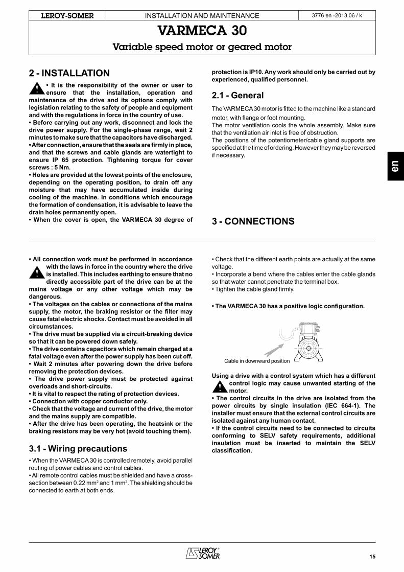
• The VARMECA 30 has a positive logic configuration.
Using a drive with a control system which has a different control logic may cause unwanted starting of the motor.
• The control circuits in the drive are isolated from the power circuits by single insulation (IEC 664-1). The installer must ensure that the external control circuits are isolated against any human contact.• If the control circuits need to be connected to circuits conforming to SELV safety requirements, additional insulation must be inserted to maintain the SELV classification.
2 - INSTALLATION• It is the responsibility of the owner or user to ensure that the installation, operation and
maintenance of the drive and its options comply with legislation relating to the safety of people and equipment and with the regulations in force in the country of use.• Before carrying out any work, disconnect and lock the drive power supply. For the single-phase range, wait 2 minutes to make sure that the capacitors have discharged.• After connection, ensure that the seals are firmly in place, and that the screws and cable glands are watertight to ensure IP 65 protection. Tightening torque for cover screws : 5 Nm.• Holes are provided at the lowest points of the enclosure, depending on the operating position, to drain off any moisture that may have accumulated inside during cooling of the machine. In conditions which encourage the formation of condensation, it is advisable to leave the drain holes permanently open.• When the cover is open, the VARMECA 30 degree of
protection is IP10. Any work should only be carried out by experienced, qualified personnel.
2.1 - Generalthe VaRmeca 30 motor is fitted to the machine like a standard motor, with flange or foot mounting.the motor ventilation cools the whole assembly. make sure that the ventilation air inlet is free of obstruction.the positions of the potentiometer/cable gland supports are specified at the time of ordering. However they may be reversed if necessary.
3 - CONNECTIONS
cable in downward position
16
2013.06 / kLEROY-SOMER InstallatIon anD maIntenance
VARMECA 30Variable speed motor or geared motor
3776 en -
3.2 - Control terminal blocks
• Check that the terminal block has been removed from its fixed holder (unplugged) before making any connections, so as to avoid putting pressure on the card.
• The VARMECA has a positive logic configuration. Using a drive with a control system which has a different control logic may cause unwanted starting of the motor.• The control circuits in the drive are isolated from the power circuits by single insulation (IEC 664-1).The installer must ensure that the external control circuits are isolated against any human contact.• If the control circuits need to be connected to circuits conforming to SELV safety requirements, additional insulation must be inserted to maintain the SELV classification.
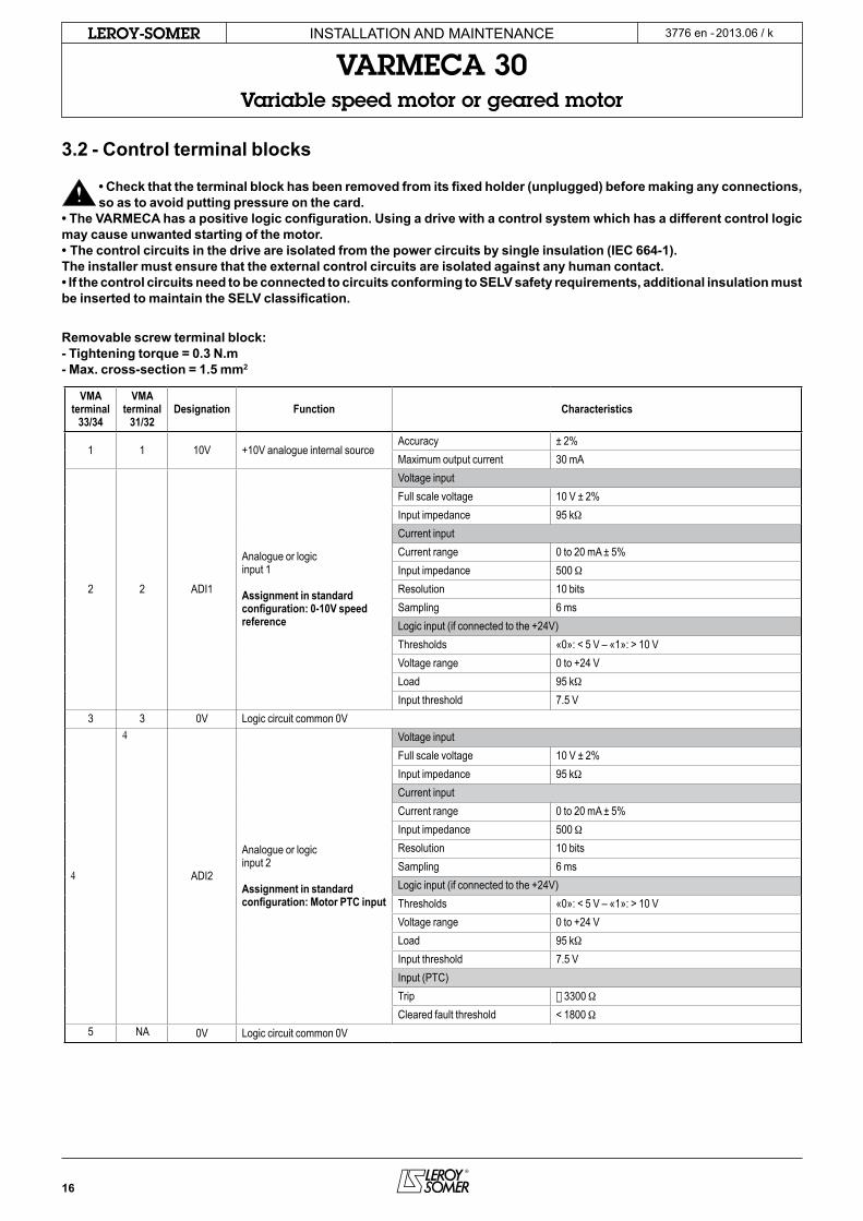
Removable screw terminal block:- Tightening torque = 0.3 N.m- Max. cross-section = 1.5 mm2
VMA terminal
33/34
VMA terminal
31/32Designation Function Characteristics
1 1 10V +10V analogue internal sourceaccuracy ± 2%maximum output current 30 ma
2 2 aDI1
analogue or logic input 1
Assignment in standard configuration: 0-10V speed reference
Voltage inputFull scale voltage 10 V ± 2%Input impedance 95 kWcurrent inputcurrent range 0 to 20 ma ± 5%Input impedance 500 WResolution 10 bitssampling 6 mslogic input (if connected to the +24V)thresholds «0»: < 5 V – «1»: > 10 VVoltage range 0 to +24 Vload 95 kWInput threshold 7.5 V
3 3 0V logic circuit common 0V
4
4
aDI2
analogue or logic input 2
Assignment in standard configuration: Motor PTC input
Voltage inputFull scale voltage 10 V ± 2%Input impedance 95 kWcurrent inputcurrent range 0 to 20 ma ± 5%Input impedance 500 WResolution 10 bitssampling 6 mslogic input (if connected to the +24V)thresholds «0»: < 5 V – «1»: > 10 VVoltage range 0 to +24 Vload 95 kWInput threshold 7.5 VInput (Ptc)trip Š 3300 Wcleared fault threshold < 1800 W
5 na 0V logic circuit common 0V
17
2013.06 / kLEROY-SOMER
en
InstallatIon anD maIntenance
VARMECA 30Variable speed motor or geared motor
3776 en -
VMA terminal
33/34
VMA terminal
31/32Designation Function Characteristics
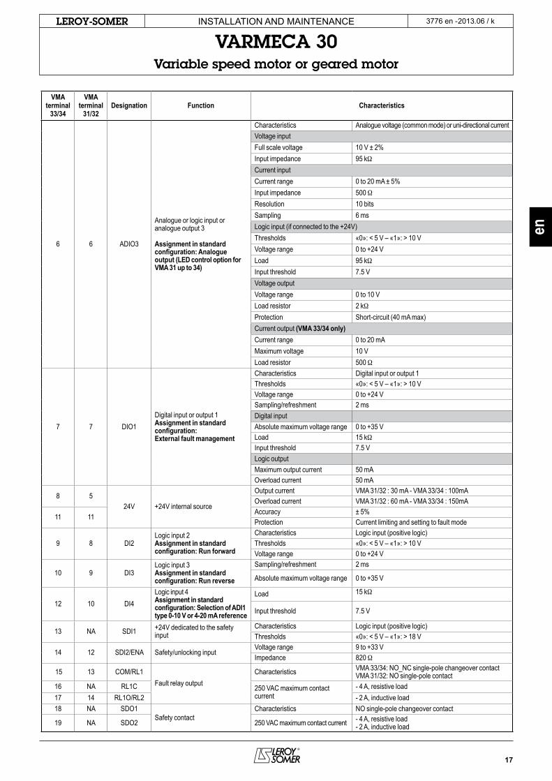
6 6 aDIo3
analogue or logic input or analogue output 3
Assignment in standard configuration: Analogue output (LED control option for VMA 31 up to 34)
characteristics analogue voltage (common mode) or uni-directional currentVoltage inputFull scale voltage 10 V ± 2%Input impedance 95 kWcurrent inputcurrent range 0 to 20 ma ± 5%Input impedance 500 WResolution 10 bitssampling 6 mslogic input (if connected to the +24V)thresholds «0»: < 5 V – «1»: > 10 VVoltage range 0 to +24 Vload 95 kWInput threshold 7.5 VVoltage outputVoltage range 0 to 10 Vload resistor 2 kWProtection short-circuit (40 ma max)current output (VMA 33/34 only)current range 0 to 20 mamaximum voltage 10 Vload resistor 500 W
7 7 DIo1Digital input or output 1Assignment in standard configuration: External fault management
characteristics Digital input or output 1thresholds «0»: < 5 V – «1»: > 10 VVoltage range 0 to +24 Vsampling/refreshment 2 msDigital input absolute maximum voltage range 0 to +35 Vload 15 kWInput threshold 7.5 Vlogic output maximum output current 50 maoverload current 50 ma
8 524V +24V internal source
output current Vma 31/32 : 30 ma - Vma 33/34 : 100maoverload current Vma 31/32 : 60 ma - Vma 33/34 : 150ma
11 11accuracy ± 5%Protection current limiting and setting to fault mode
9 8 DI2logic input 2Assignment in standard configuration: Run forward
characteristics logic input (positive logic)thresholds «0»: < 5 V – «1»: > 10 VVoltage range 0 to +24 V
10 9 DI3logic input 3Assignment in standard configuration: Run reverse
sampling/refreshment 2 ms
absolute maximum voltage range 0 to +35 V
12 10 DI4logic input 4Assignment in standard configuration: Selection of ADI1 type 0-10 V or 4-20 mA reference
load 15 kW
Input threshold 7.5 V
13 na sDI1 +24V dedicated to the safety input
characteristics logic input (positive logic)thresholds «0»: < 5 V – «1»: > 18 V
14 12 sDI2/ena safety/unlocking inputVoltage range 9 to +33 VImpedance 820 W
15 13 com/Rl1Fault relay output
characteristics Vma 33/34: no_nc single-pole changeover contactVma 31/32: no single-pole contact
16 na Rl1c 250 Vac maximum contact current
- 4 a, resistive load17 14 Rl1o/Rl2 - 2 a, inductive load18 na sDo1
safety contactcharacteristics no single-pole changeover contact
19 na sDo2 250 Vac maximum contact current - 4 a, resistive load- 2 a, inductive load
18
2013.06 / kLEROY-SOMER
PB1 & PB2
RJ 45
P2
VMA 31/32
VMA 33/34
SLOT 1
SLOT 2
RJ 45
PB 1 PB 2
InstallatIon anD maIntenance
VARMECA 30Variable speed motor or geared motor
3776 en -
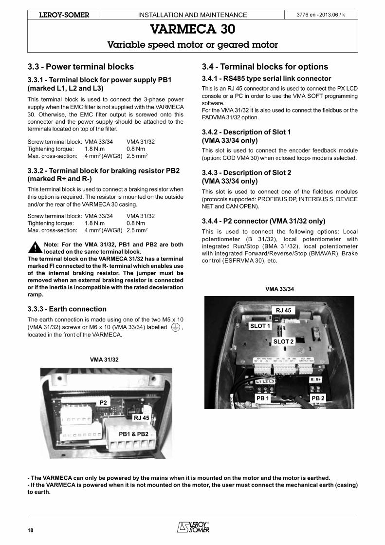
3.3 - Power terminal blocks3.3.1 - Terminal block for power supply PB1 (marked L1, L2 and L3)this terminal block is used to connect the 3-phase power supply when the emc filter is not supplied with the VaRmeca 30. otherwise, the emc filter output is screwed onto this connector and the power supply should be attached to the terminals located on top of the filter.
screw terminal block: Vma 33/34 Vma 31/32tightening torque: 1.8 n.m 0.8 nmmax. cross-section: 4 mm2 (aWG8) 2.5 mm2
3.3.2 - Terminal block for braking resistor PB2 (marked R+ and R-)this terminal block is used to connect a braking resistor when this option is required. the resistor is mounted on the outside and/or the rear of the VaRmeca 30 casing.
screw terminal block: Vma 33/34 Vma 31/32tightening torque: 1.8 n.m 0.8 nmmax. cross-section: 4 mm2 (aWG8) 2.5 mm2
Note: For the VMA 31/32, PB1 and PB2 are both located on the same terminal block.
The terminal block on the VARMECA 31/32 has a terminal marked FI connected to the R- terminal which enables use of the internal braking resistor. The jumper must be removed when an external braking resistor is connected or if the inertia is incompatible with the rated deceleration ramp.
3.3.3 - Earth connectionthe earth connection is made using one of the two m5 x 10 (Vma 31/32) screws or m6 x 10 (Vma 33/34) labelled , located in the front of the VaRmeca.
3.4 - Terminal blocks for options3.4.1 - RS485 type serial link connectorthis is an RJ 45 connector and is used to connect the PX lcD console or a Pc in order to use the Vma soFt programming software.For the Vma 31/32 it is also used to connect the fieldbus or the PaDVma 31/32 option.
3.4.2 - Description of Slot 1 (VMA 33/34 only)this slot is used to connect the encoder feedback module (option: coD Vma 30) when «closed loop» mode is selected.
3.4.3 - Description of Slot 2 (VMA 33/34 only)this slot is used to connect one of the fieldbus modules (protocols supported: PRoFIBUs DP, InteRBUs s, DeVIce net and can oPen).
3.4.4 - P2 connector (VMA 31/32 only)this is used to connect the following options: local potentiometer (B 31/32), local potentiometer with integrated Run/stop (Bma 31/32), local potentiometer with integrated Forward/Reverse/stop (BmaVaR), Brake control (esFRVma 30), etc.
- The VARMECA can only be powered by the mains when it is mounted on the motor and the motor is earthed.- If the VARMECA is powered when it is not mounted on the motor, the user must connect the mechanical earth (casing) to earth.
19
2013.06 / kLEROY-SOMER
QS
10VADI10VADI224VADIO3
DI01
DI2DI3Dl4
+24VENA
RL1RL2
L1L2L3
R+
R-
Fi
23456
1
89
10
1112
7
1314
VARMECA 31/32
QS
10VADI10VADI20VADIO3
DI01+24VDI2DI3+24VDI4SDI1SDI2
COMRL1CRL10SD01SD02
L1L2L3
R+
R-
23456
1
89
1011121314
7
1516171819
VARMECA 33/34
en
InstallatIon anD maIntenance
VARMECA 30Variable speed motor or geared motor
3776 en -
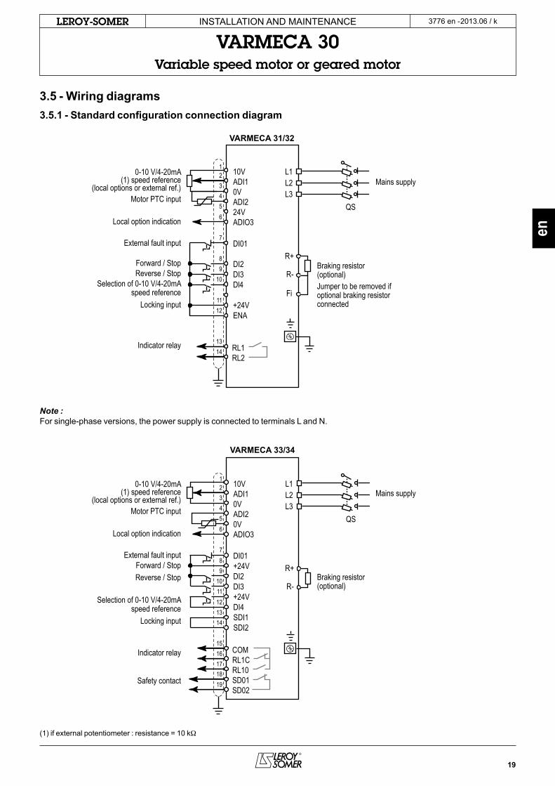
3.5 - Wiring diagrams3.5.1 - Standard configuration connection diagram
Note :For single-phase versions, the power supply is connected to terminals l and n.
(1) if external potentiometer : resistance = 10 kW
0-10 V/4-20mA(1) speed reference
(local options or external ref.)Motor PTC input
Local option indication
External fault input
Forward / StopReverse / Stop
Selection of 0-10 V/4-20mAspeed reference
Locking input
Indicator relay
0-10 V/4-20mA(1) speed reference
(local options or external ref.)Motor PTC input
Local option indication
External fault inputForward / StopReverse / Stop
Selection of 0-10 V/4-20mAspeed reference
Locking input
Indicator relay
Safety contact
Mains supply
Mains supply
Braking resistor(optional)Jumper to be removed ifoptional braking resistorconnected
Braking resistor(optional)

20
2013.06 / kLEROY-SOMER InstallatIon anD maIntenance
VARMECA 30Variable speed motor or geared motor
3776 en -
3.5.2 - Connection diagram with safety input3.5.2.1 - Safety inputthis input, when opened, causes the drive to lock. Independent of the microprocessor, it acts on several levels of control from the power bridge. It is designed in such a way that even if one or more circuit components were to fail, the absence of torque on the motor shaft is guaranteed with a very high level of integrity.this input is used to create a safety function using the principles of category 1 or 3 of standard en954-1, depending on the application diagram.the design of the «freewheel stop» function using input sDI2 has been evaluated by cetIm.the results of this examination are recorded in report no. 732773/47a.this built-in functionality enables the drive to act as substitute for a contactor in order to stop the motor in freewheel mode.By using this safety input redundantly with another drive logic input, a diagram can be used which is capable of resisting a single fault. the drive will stop the motor in freewheel mode using two different control channels.For correct use, the power connection diagrams described in the following paragraphs must be adhered to.to unlock the drive and provide the safety function, safety input ena (Vma 31/32) or sDI2 (Vma 33/34) must be connected to the +24V source (sDI1 for Vma 33/34).this +24V source should be reserved exclusively for the safety input function (Vma33/34).
• The safety input is a safety component which must be incorporated into the complete system dedicated
to machine safety. As for any installation, the complete machine must be the subject of a risk analysis by the integrator which will determine the safety category with which the installation must comply. • The safety input, when open, locks the drive, meaning the dynamic braking function is no longer available. If a braking function is required before the drive safety lock is applied, a time-delayed safety relay should be installed to activate locking automatically after the end of braking. If braking needs to be a machine safety function, it should be provided by an electromechanical solution since the dynamic braking by the drive function is not considered to be a safety function. • The safety input does not provide the electrical isolation function. Before any work is carried out, the power supply must be cut by an approved isolating device (isolator, switch, etc).
• The safety function is not enabled when the drive is controlled via the keypad or via a fieldbus.
21
2013.06 / kLEROY-SOMER
AUQS
QS
10VADI10VADI224VADIO3
DI01
DI2DI3DI4
+24VENA
RL1RL2
L1L2L3
R+
R-
Fi
VARMECA 31/32
23456
1
89
10
1112
7
1314
QS
10VADI10VADI20VADIO3
DI01+24VDI2DI3+24VDI4SDI1SDI2
COMRL1CRL10SD01SD02
L1L2L3
R+
R-
23456
1
89
1011121314
7
1516171819
VARMECA 33/34
AUQS
en
InstallatIon anD maIntenance
VARMECA 30Variable speed motor or geared motor
3776 en -
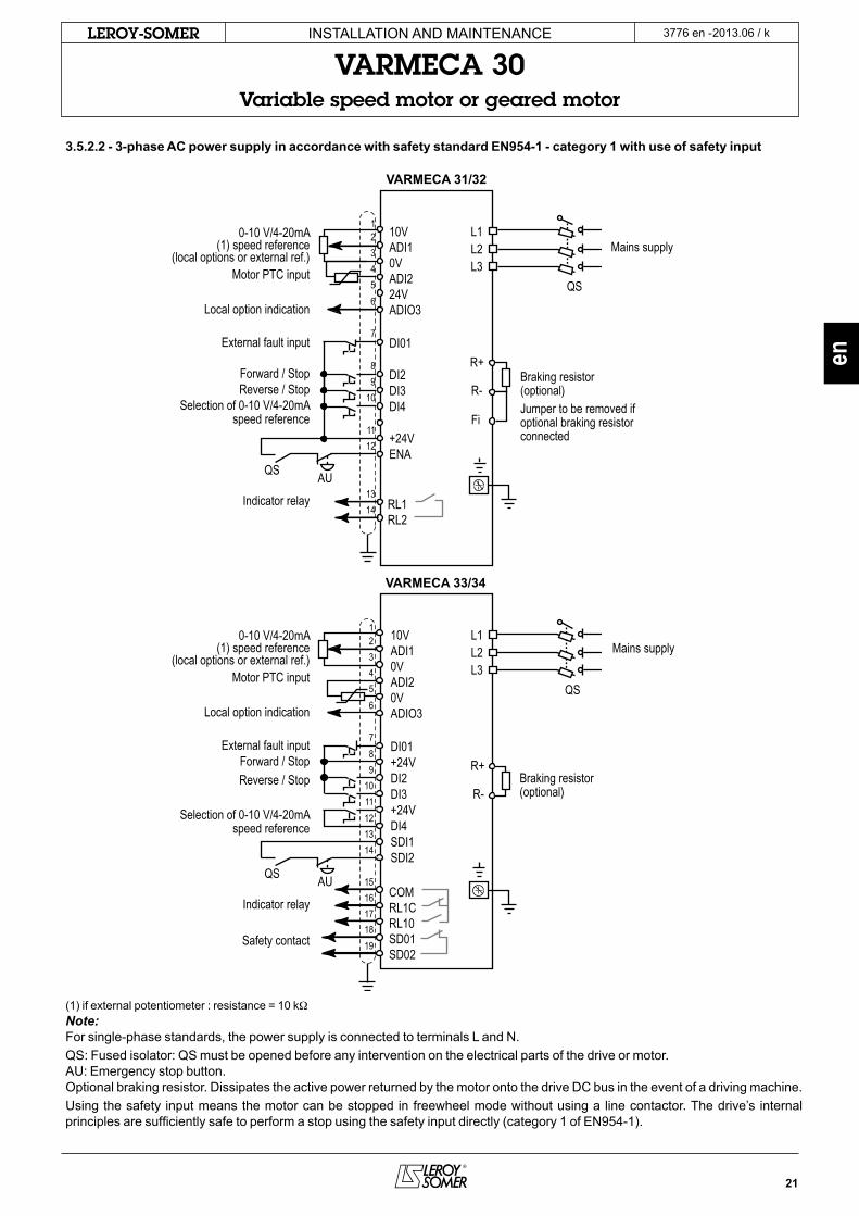
3.5.2.2 - 3-phase AC power supply in accordance with safety standard EN954-1 - category 1 with use of safety input
(1) if external potentiometer : resistance = 10 kWNote:For single-phase standards, the power supply is connected to terminals l and n.Qs: Fused isolator: Qs must be opened before any intervention on the electrical parts of the drive or motor.aU: emergency stop button.optional braking resistor. Dissipates the active power returned by the motor onto the drive Dc bus in the event of a driving machine.Using the safety input means the motor can be stopped in freewheel mode without using a line contactor. the drive’s internal principles are sufficiently safe to perform a stop using the safety input directly (category 1 of en954-1).
0-10 V/4-20mA(1) speed reference
(local options or external ref.)Motor PTC input
Local option indication
External fault input
Forward / StopReverse / Stop
Selection of 0-10 V/4-20mAspeed reference
Indicator relay
0-10 V/4-20mA(1) speed reference
(local options or external ref.)Motor PTC input
Local option indication
External fault inputForward / StopReverse / Stop
Selection of 0-10 V/4-20mAspeed reference
Indicator relay
Safety contact
Mains supply
Mains supply
Braking resistor(optional)Jumper to be removed ifoptional braking resistorconnected
Braking resistor(optional)
22
2013.06 / kLEROY-SOMER
0.37
0.39
0.41 0.42
0.40
F2F1
InstallatIon anD maIntenance
VARMECA 30Variable speed motor or geared motor
3776 en -
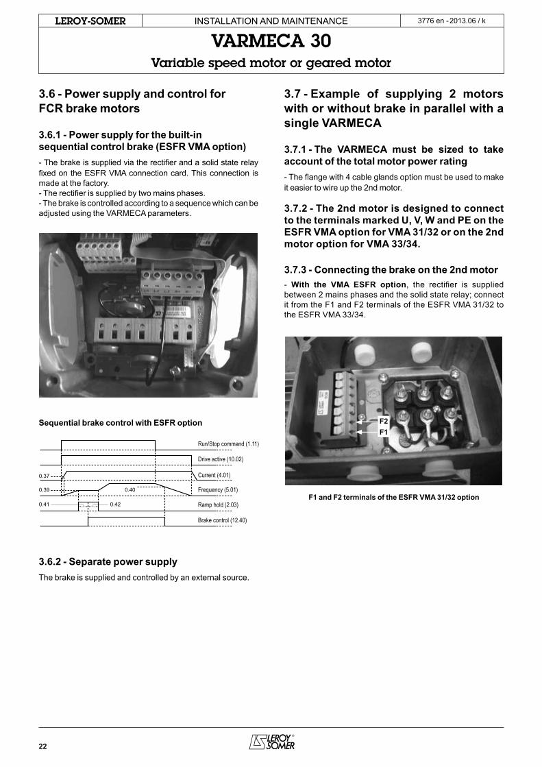
3.6 - Power supply and control for FCR brake motors
3.6.1 - Power supply for the built-in sequential control brake (ESFR VMA option)- the brake is supplied via the rectifier and a solid state relay fixed on the esFR Vma connection card. this connection is made at the factory.- the rectifier is supplied by two mains phases.- the brake is controlled according to a sequence which can be adjusted using the VaRmeca parameters.
Sequential brake control with ESFR option
3.6.2 - Separate power supplythe brake is supplied and controlled by an external source.
3.7 - Example of supplying 2 motors with or without brake in parallel with a single VARMECA
3.7.1 - The VARMECA must be sized to take account of the total motor power rating- the flange with 4 cable glands option must be used to make it easier to wire up the 2nd motor.
3.7.2 - The 2nd motor is designed to connect to the terminals marked U, V, W and PE on the ESFR VMA option for VMA 31/32 or on the 2nd motor option for VMA 33/34.
3.7.3 - Connecting the brake on the 2nd motor- With the VMA ESFR option, the rectifier is supplied between 2 mains phases and the solid state relay; connect it from the F1 and F2 terminals of the esFR Vma 31/32 to the esFR Vma 33/34.
F1 and F2 terminals of the ESFR VMA 31/32 option
Run/Stop command (1.11)
Drive active (10.02)
Current (4.01)
Frequency (5.01)
Ramp hold (2.03)
Brake control (12.40)

23
2013.06 / kLEROY-SOMER
U
V
W
180VDC
112
2
U
ESFRPE
PE
VW+- F2
L1 L2 L3
F1
L1
L3
S08
+ ++
Opto Triac
Fu
1.25 A600 V
L1
L3
F1
F2
en
InstallatIon anD maIntenance
VARMECA 30Variable speed motor or geared motor
3776 en -
3.8 - Wiring diagrams for the ESFR VMA option3.8.1 - Connection of the ESFR VMA 31/32 option
3.8.2 - Connection of the ESFR VMA 33/34 option
230/400Vmains supply*
Flex trip to connectorfor options
Full-wave(208-240VACmains supply)
Power supply to 2nd motor(variable frequency and voltage output)
Half-wave(380-480VAC mainssupply)
Power supply to 2nd brake(mains voltage output)
Coilbrake
*Note : With single-phase drive, connect power supply between L and N.
: 400/480V mains supply: 230V mains supply
Brake
Dedicated logic output
VMA 33/34T : 180VDCVMA 33/34TL : 100VDC
AC power supply outputfor a 2nd brake

24
2013.06 / kLEROY-SOMER InstallatIon anD maIntenance
VARMECA 30Variable speed motor or geared motor
3776 en -
Brake connectionon + and - terminals
F1 and F2 outputfor a 2nd brake
Dedicated logicoutput connection
Power supply onthe L1 and L3 terminals

25
2013.06 / kLEROY-SOMER
en
InstallatIon anD maIntenance
VARMECA 30Variable speed motor or geared motor
3776 en -
4 - COMMISSIONING• Before switching on the VARMECA 30, check that the electrical connections are correct, and that any
moving parts are mechanically protected.• For the safety of personnel, the VARMECA 30 must not be switched on with the protective cover removed.
4.1 - Starting with the power supplysince the run command has been factory-enabled via a jumper, the motor starts as soon as it is switched on.the speed is adjusted with the local control knob (B 31/32 or B 33/34 option) or a remote reference (0-10 V or 4-20 ma).Power-up: the green indicator lamp is lit continuously.the control terminals sDI1 and sDI2 (Vma 33/34) or 11 and 12 (Vma 31/32) are linked (unlocking).
4.1.1 - Automatic starting By leaving the wire between control terminals 8 and 11 (Vma 31/32) or DI2 and +24V (Vma 33/34), the motor starts running forward.
4.2 - Starting with remote volt-free contactonce it has been switched on, the motor starts in accordance with the run command given by the closing of the volt-free contact corresponding to the desired direction of rotation.the speed is adjusted with the local control knob (B 31/32 or B 33/34 option) or a remote reference (0-10 V or 4-20 ma).
4.3 - Starting with local run/stop control (BMA 31/32, BMA 33/34 or BMAVAR 31/32, BMAVAR 33/34 optiononce it has been switched on, the motor starts after the control knob corresponding to the desired direction of rotation has been pressed for one second.the speed is only adjusted with the local control knob.
4.4 - Setting the speed4.4.1 - External referenceadjust the speed reference using the chosen reference (0/10 V or 4/20 ma).
4.4.2 - Control knob options (B 31/32 or B 33/34) and remote potentiometer optionadjust the speed reference using the control knob or the 10 kW remote potentiometer.
4.4.3 - Internal speed control option (CVI VMA 31/32 or CVI VMA 33/34)adjust the speed reference using the Int. spd. potentiometer.adjust the max. spd. or min. spd. potentiometers if it is not possible to reach the desired speed.

26
2013.06 / kLEROY-SOMER InstallatIon anD maIntenance
VARMECA 30Variable speed motor or geared motor
3776 en -
5 - FAULTS - DIAGNOSTICSInformation relating to the status of the VaRmeca 30 is provided by two indicator lamps located on the local control options (B 31/32 or B 33/34, Bma 31/32 or Bma 33/34, BmaVaR 31/32 or BmaVaR 33/34, cVI Vma 31/32 or cVI Vma 33/34 options), or by the internal leD in Vma 31/32.
Colour and state of indic. lamp VARMECA status Checks to be performed
steady green no tripmains present
Flashing green current limiting • check that the motor is not overloaded or stalled
Flashing redIGBt temperature alarmmotor overloadBraking resistor option overload
• check that air is able to circulate around the motor fins and VaRmeca casing• the motor is overloaded: check the motor current using a clamp ammeter• check that the deceleration ramp is long enough for applications with high inertia
steady red
• short-circuit of a motor winding• locked motor rotor• Faulty insulation of a winding• I2t overheating• Internal fault• Undervoltage• overvoltage
• check that no incident has occurred• switch off and then on again to clear the fault.• check the mains voltage• check that the deceleration ramp is long enough for applications with high inertia• If the fault remains, consult leRoY-someR
the fault is cleared by switching off the VaRmeca 30 or by opening/closing the connection between terminals 12: ena and 11: +24 V (Vma 31/32) or sDI1 and sDI2 (Vma 33/34).When a no-load test is carried out (i.e. with the motor disconnected), motor operation may appear unstable. this instability manifests itself in the form of vibration and, in extreme cases, in a fault (overload, overcurrent or braking resistor overload). However, the instability disappears as soon as the motor is loaded. to remove this instability during a no-load test, set parameter 5.13 to DYnamIc. to return to normal machine operating conditions, reset parameter 5.13 to FIXeD.If the problem persists, contact leroy-somer.
6 - MAINTENANCE• All work relating to installation, commissioning and maintenance must be carried out by
experienced, qualified personnel.• Before carrying out any work, disconnect and lock the VARMECA 30 power supply circuit and wait 2 minutes for the capacitors to discharge.
6.1 - Careno special care is required on the VaRmeca 30, apart from the regular removal of dust from the fan grille and the cooling fins located at the bottom of the casing.Do not dismantle the VaRmeca 30 while it is still under guarantee, as this would then immediately become null and void.CAUTION: certain components which are sensitive to electrostatic discharge may be destroyed simply by touching them. Do not leave any metal object in the connection area, as this could cause a short-circuit.
6.2 - Measurements6.2.1 - Generalthe input voltages can be measured using ordinary instruments.
the motor current Is not measUReD on tHe VaRmeca 30 PoWeR sUPPlY (l1, l2, l3).It is measured using an ordinary clamp ammeter on one of the wires which goes into the motor terminal block.
6.2.2 - Procedure for measuring the motor current on VMA 31/32 (if the motor wire loop is inaccessible)- open the VaRmeca 30 power supply circuit and lock it.- Wait 2 minutes for the capacitors to discharge (for the single-phase range).- open the cover of the VaRmeca 30.- open the connection between terminals sDI1 and sDI2 (Vma 33/34) or 11 and 12 (Vma 31/32).- Remove the toRX + slot type screws from the protection plate above the motor terminals.- Pass the longest motor wire along the side of the protection circuit.- Replace the protection plate and fasten it.- Pass the clamp ammeter through the motor wire loop.- Remake the connection between terminals sDI1 and sDI2 (Vma 33/34) or 11 and 12 (Vma 31/32).
27
2013.06 / kLEROY-SOMER
1 2 3en
InstallatIon anD maIntenance
VARMECA 30Variable speed motor or geared motor
3776 en -
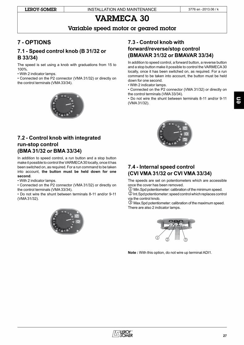
7 - OPTIONS7.1 - Speed control knob (B 31/32 or B 33/34)the speed is set using a knob with graduations from 15 to 100%.• With 2 indicator lamps.• connected on the P2 connector (Vma 31/32) or directly on the control terminals (Vma 33/34).
7.2 - Control knob with integrated run-stop control (BMA 31/32 or BMA 33/34)In addition to speed control, a run button and a stop button make it possible to control the VaRmeca 30 locally, once it has been switched on, as required. For a run command to be taken into account, the button must be held down for one second.• With 2 indicator lamps.• connected on the P2 connector (Vma 31/32) or directly on the control terminals (Vma 33/34).• Do not wire the shunt between terminals 8-11 and/or 9-11 (Vma 31/32).
7.3 - Control knob with forward/reverse/stop control (BMAVAR 31/32 or BMAVAR 33/34)In addition to speed control, a forward button, a reverse button and a stop button make it possible to control the VaRmeca 30 locally, once it has been switched on, as required. For a run command to be taken into account, the button must be held down for one second.• With 2 indicator lamps.• connected on the P2 connector (Vma 31/32) or directly on the control terminals (Vma 33/34).• Do not wire the shunt between terminals 8-11 and/or 9-11 (Vma 31/32).
7.4 - Internal speed control (CVI VMA 31/32 or CVI VMA 33/34)the speeds are set on potentiometers which are accessible once the cover has been removed.j min.spd potentiometer: calibration of the minimum speed.k Int.spd potentiometer: speed control which replaces control via the control knob.l max.spd potentiometer: calibration of the maximum speed. there are also 2 indicator lamps.
Note : With this option, do not wire up terminal aDI1.
28
2013.06 / kLEROY-SOMER InstallatIon anD maIntenance
VARMECA 30Variable speed motor or geared motor
3776 en -
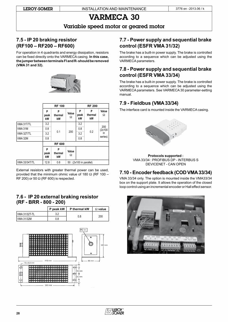
7.5 - IP 20 braking resistor (RF100 – RF200 – RF600)For operation in 4 quadrants and energy dissipation, resistors can be fixed directly onto the VaRmeca casing. In this case, the jumper between terminals FI and R- should be removed (VMA 31 and 32).
RF 100 RF 200
PpeakkW
PthermalkW
ValueW
PpeakkW
PthermalkW
ValueW
VMA 31T/TL 3.2
0.1 200
3.2
0.2200
(2x100in
series)
VMA 31M 0.8 0.8VMA 32T/TL 3.2 3.2VMA 32M 0.8 0.8
RF 600
PpeakkW
PthermalkW
ValueW
VMA 33/34T/TL 12.8 0.6 50 : (2x100 in parallel)
external resistors with greater thermal power can be used, provided that the minimum ohmic value of 180 W (RF 100 – RF 200) or 50 W (RF 600) is respected.
7.6 - IP 20 external braking resistor (RF - BRR - 800 - 200)
P peak kW P thermal kW W valueVMA 31/32T-TL 3.2
0.8 200VMA 31/32M 0.8
7.7 - Power supply and sequential brake control (ESFR VMA 31/32)the brake has a built-in power supply. the brake is controlled according to a sequence which can be adjusted using the VaRmeca parameters.
7.8 - Power supply and sequential brake control (ESFR VMA 33/34)the brake has a built-in power supply. the brake is controlled according to a sequence which can be adjusted using the VaRmeca parameters. see VaRmeca 30 parameter-setting manual.
7.9 - Fieldbus (VMA 33/34)the interface card is mounted inside the VaRmeca casing.
Protocols supported : Vma 33/34 : PRoFIBUs DP - InteRBUs s
DeVIcenet - can oPen
7.10 - Encoder feedback (COD VMA 33/34)Vma 33/34 only. the option is mounted inside the Vma33/34 box on the support plate. It allows the operation of the closed loop control using an incremental encoder or Hall effect sensor.

29
2013.06 / kLEROY-SOMER
AVARMECA PADVMA30
D
B
E
FG
C
en
InstallatIon anD maIntenance
VARMECA 30Variable speed motor or geared motor
3776 en -
7.11 - Parameter-setting console (PX LCD)the console option provides access to the drive internal settings (terminal block configuration, ramp, speed and PI settings, etc).see VaRmeca 30 parameter-setting manual.Description of the option:1 PX lcD console, 1 cable l = 3 m
PX LCD parameter-setting console
7.12 - Parameter-setting software (VMA SOFT)this option provides access to the drive internal settings from a Pc. the software is compatible with WInDoWs 7.see VaRmeca 30 parameter-setting manual.Description of the option:1 cable l = 1.5 mthe software can be downloaded directly from the Web : www.leroysomer.com.
7.13 - Operator display (PAD VMA 30)Presentation of the operator display :the PaDVma30 operator display consists of a display unit, three control buttons and three parameter-setting keys.
Ref. Function
a
Display comprising 4 x 7-segment digits for indicating:- the drive operating status- certain operating data- the adjustment parameters (01 to 80)and their value.
B leD providing a sign for the data (the lit leD corresponds to the «-» sign).
cKeys which can be used to scroll up and down through the parameters or their value. these keys can also be used to vary the speed.
DKeys which can be used to switch from standard mode to parameter-setting mode.In parameter-setting mode, the parameter number and value are displayed alternately on the display.
e
F
G
In keypad mode, these buttons are used for the following commands:
- reverse,
- stop, clear fault,
- forward.
the parameter setting to use the PaD Vma30 is described in the Parameter setting document 3847.
7.14 - XPress Key (PX Key)7.14.1 - Generalthe XPress Key option is used to save a copy of all the VaRmeca 30 parameters so that they can be duplicated very simply in another drive.
7.14.2 - Setting drive parameters with XPress Key• connect XPress Key to the serial port via a RJ45 connector.• With the drive locked, press the «Key» button for a first time. confirm the transfer of parameters into the drive by pressing the «Key» button a second time.
CAUTION: If confirmation is not received within 10 seconds, the procedure is cancelled.
30
2013.06 / kLEROY-SOMER
L1 L2 L3
InstallatIon anD maIntenance
VARMECA 30Variable speed motor or geared motor
3776 en -
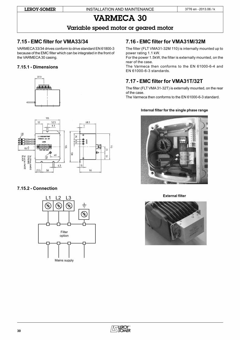
7.15 - EMC filter for VMA33/34VaRmeca 33/34 drives conform to drive standard en 61800-3 because of the emc filter which can be integrated in the front of the VaRmeca 30 casing.
7.15.1 - Dimensions
7.15.2 - Connection
7.16 - EMC filter for VMA31M/32Mthe filter (Flt Vma31-32m 110) is internally mounted up to power rating 1.1 kW.For the power 1.5kW, the filter is externally mounted, on the rear of the case.the Varmeca then conforms to the en 61000-6-4 and en 61000-6-3 standards.
7.17 - EMC filter for VMA31T/32Tthe filter (Flt Vma 31-32t) is externally mounted, on the rear of the case.the Varmeca then conforms to the en 61000-6-3 standard.
Internal filter for the single phase range
External filter
Filteroption
mains supply


