Lesson 6 – Shaft Excavation and Cleaning Welcome to the Drilled Shaft Inspector Course. This is Lesson 6, Shaft Excavation and Cleaning. To begin, select the start button or press Shift+N on your keyboard. In this lesson, we will take a look at the following objectives: • Perform inspection of drilled shaft excavations for compliance to plans, tolerances and cleanliness. • Perform visual field verification of soil/rock material for comparison to supplied soil boring data/logs. • Sample and test slurry and fluid in the excavation. • Calculate Elevations & Extra Shaft Lengths. • Identify the applicable 455 Specifications Checklist The checklist can be used to assist in performing our duties when the Contractor and equipment arrive on-site. Please read the items indicated for test hole/test shaft requirements. Test holes or test shafts are separate drilled shafts that the contractor must perform to demonstrate to the Department that the proposed means and methods are successful to produce drilled shafts in accordance with our specifications. Checklist In shafts for miscellaneous structures the specifications gives an exception and the first production shaft is considered the test hole. If a test hole is not successful, the Contractor will need to revise his Drilled Shaft Installation Plan. Test holes are required to be cut-off a minimum of 2 ft. below the ground line. 455-1.4-vibrations…Placed Concrete In drilled shaft installation, installation of temporary casing using vibratory hammers may cause significant vibrations in the vicinity. Freshly placed concrete may be affected by the vibrations produced by the use of vibratory hammers installing or removing casing. Freshly placed concrete may refer to a recently placed drilled shaft concrete or concrete placed for another structure nearby. 455-1.4-vibrations…Placed Concrete Let’s review the specification requirements regarding vibrations on freshly placed concrete. Ensure that freshly placed concrete is not subjected to vibrations greater than 1.5 in/sec from pile driving and/or drilled shaft casing installation sources located within the greater dimension of three shaft diameters (measured from the perimeter of the shaft closest to the vibration source) or 30 feet (from the nearest outside edge of freshly placed concrete to the vibration source) until that concrete has attained its final set as defined by ASTM C-403 except as required to remove temporary casings before the drilled shaft elapsed time has expired. 455-15.1.1 - Templates Let’s review the template requirements: Provide a fixed template, adequate to maintain shaft position and alignment during all excavation and concreting operations, when drilling from a barge. Do not use floating templates (attached to a barge). The Engineer will not require a template for shafts drilled on land provided the Contractor demonstrates satisfactorily to the Engineer that shaft position and alignment can be properly maintained. 455-15.1.1 - Templates The Engineer will require a fixed template, adequate to maintain shaft position and alignment during all excavation and concreting operations, for shafts drilled on land when the Contractor fails to demonstrate satisfactorily that he can properly maintain shaft position and alignment without use of a template. 455-18 – Test Holes The purpose of specifying a Test Hole (test shaft) is twofold: first, to insure that the Contractor has the necessary expertise to complete the work successfully and, second, to determine if the proposed equipment and drilling procedures are adequate for the site conditions. 455-18 – Test Holes Let’s read the highlighted portion of the specification: The Engineer will use the construction of test holes to determine if the methods and equipment used by the Contractor are sufficient to produce a shaft excavation meeting the requirements of the Contract Documents. Page 1
Transcript
Lesson 6 – Shaft Excavation and Cleaning
Welcome to the Drilled Shaft Inspector Course. This is Lesson 6, Shaft Excavation and Cleaning. To begin, select the start button or press Shift+N on your keyboard. In this lesson, we will take a look at the following objectives:
• Perform inspection of drilled shaft excavations for compliance to plans, tolerances and cleanliness. • Perform visual field verification of soil/rock material for comparison to supplied soil boring data/logs. • Sample and test slurry and fluid in the excavation. • Calculate Elevations & Extra Shaft Lengths. • Identify the applicable 455 Specifications
Checklist The checklist can be used to assist in performing our duties when the Contractor and equipment arrive on-site. Please read the items indicated for test hole/test shaft requirements. Test holes or test shafts are separate drilled shafts that the contractor must perform to demonstrate to the Department that the proposed means and methods are successful to produce drilled shafts in accordance with our specifications. Checklist In shafts for miscellaneous structures the specifications gives an exception and the first production shaft is considered the test hole. If a test hole is not successful, the Contractor will need to revise his Drilled Shaft Installation Plan. Test holes are required to be cut-off a minimum of 2 ft. below the ground line. 455-1.4-vibrations…Placed Concrete In drilled shaft installation, installation of temporary casing using vibratory hammers may cause significant vibrations in the vicinity. Freshly placed concrete may be affected by the vibrations produced by the use of vibratory hammers installing or removing casing. Freshly placed concrete may refer to a recently placed drilled shaft concrete or concrete placed for another structure nearby. 455-1.4-vibrations…Placed Concrete Let’s review the specification requirements regarding vibrations on freshly placed concrete. Ensure that freshly placed concrete is not subjected to vibrations greater than 1.5 in/sec from pile driving and/or drilled shaft casing installation sources located within the greater dimension of three shaft diameters (measured from the perimeter of the shaft closest to the vibration source) or 30 feet (from the nearest outside edge of freshly placed concrete to the vibration source) until that concrete has attained its final set as defined by ASTM C-403 except as required to remove temporary casings before the drilled shaft elapsed time has expired. 455-15.1.1 - Templates Let’s review the template requirements: Provide a fixed template, adequate to maintain shaft position and alignment during all excavation and concreting operations, when drilling from a barge. Do not use floating templates (attached to a barge). The Engineer will not require a template for shafts drilled on land provided the Contractor demonstrates satisfactorily to the Engineer that shaft position and alignment can be properly maintained. 455-15.1.1 - Templates The Engineer will require a fixed template, adequate to maintain shaft position and alignment during all excavation and concreting operations, for shafts drilled on land when the Contractor fails to demonstrate satisfactorily that he can properly maintain shaft position and alignment without use of a template. 455-18 – Test Holes The purpose of specifying a Test Hole (test shaft) is twofold: first, to insure that the Contractor has the necessary expertise to complete the work successfully and, second, to determine if the proposed equipment and drilling procedures are adequate for the site conditions. 455-18 – Test Holes Let’s read the highlighted portion of the specification: The Engineer will use the construction of test holes to determine if the methods and equipment used by the Contractor are sufficient to produce a shaft excavation meeting the requirements of the Contract Documents.
Page 1
455-18 – Test Holes Revise the methods and equipment as necessary at any time during the construction of the test hole when unable to satisfactorily carry out any of the necessary operations described above or when unable to control the dimensions and alignment of the shaft excavation within tolerances. 455-18 – Test Holes Drill test holes out of permanent position at the location shown in the plans or as directed by the Engineer. Ensure the diameter and depth of the test hole or holes are the same diameter and maximum depth as the production drilled shafts. 455-18 – Test Holes Reinforce the test hole unless otherwise directed in the Contract Documents. Fill the test hole with concrete in the same manner production drilled shafts will be constructed. Backfill test holes which are not filled with concrete with suitable soil in a manner satisfactory to the Engineer. 455-18 – Test Holes Leave concreted test holes in place, except remove the top of the shaft to a depth of 2 feet below the ground line…. The Inspector must verify that the Test Hole is being performed at the location indicated on the plans. The Inspector must ensure that the Test Hole is constructed in accordance with the Plans and Drilled Shaft Installation Plan. 455-18 – Test Holes The Contractor is required to leave the concreted test holes in place, except that he must remove the top of the shaft to a depth of 2 feet below the ground line 455-18 – Test Holes Let’s continue with the specification for test holes. Include the cost of all test holes in the cost of the Drilled Shafts. Make no changes in methods or equipment after initial approval without the consent of the Engineer… 455-18 – Test Holes Exception for miscellaneous structures: A separate test hole is not required for drilled shafts installed under mast arms, cantilever signs, overhead truss signs, high mast light poles or other miscellaneous structures. The first production shaft will serve as a test hole for determining acceptability of the installation method. Slide 18 – 455-18 – Test Holes Regarding drilled shafts for miscellaneous structures, The Construction Procedures Administration Manual, CPAM, in section 10.5.7, requires that when miscellaneous drilled shafts are scheduled to be installed the Project Administrator must notify the District Geotechnical Office of the schedule of drilled shaft installation. Checklist This check list is available on the resources page which can be access by selecting the “resources” button on the bottom of this page. 455-15.10.1 – General Now let’s review the general requirements for drilled shaft construction methods and equipment. All shaft excavation is Unclassified Shaft Excavation. The Engineer will require Drilled Shaft Sidewall Over-reaming when inspections show it to be necessary. These terms are defined in 455-15.10.2, 455-15.10.3, and 455-15.10.4, respectively. 455-15.10.1 – General Use excavation and drilling equipment having adequate capacity, including power, torque, and crowd (down thrust), and excavation and over-reaming tools of adequate design, size, and strength to perform the work shown in the plans or described herein.…. 455-15.10.1 – General When the material encountered cannot be drilled using conventional earth augers and/or under-reaming tools, provide special drilling equipment, including but not limited to rock augers, core barrels, rock tools, air tools, blasting materials, and other equipment as necessary to continue the shaft excavation to the size and depth required. 455-15.10.2 – Unclassified Shaft Excavation Unclassified Shaft Excavation is defined as all processes required to excavate a drilled shaft of the dimensions shown in the Contract Documents to the depth indicated in the plans plus 15 feet or plus 3 shaft diameters, whichever is deeper, completed and accepted. Include in the work all shaft excavation, whether the material encountered is soil, rock, weathered rock, stone, natural or man-made obstructions, or materials of other descriptions.
Page 2
455-15.10.2 – Unclassified Shaft Excavation This video shows the tool and fluid being added during the excavation process and the tool being removed from the hole. Note the Kelly bar turning and during the removal, the length of the tool beyond the end of the Kelly bar. Tool length generally needs to be accounted for when determining depth. 455-15.10.2 – Unclassified Extra Depth Excavation Unclassified Extra Depth Excavation is defined as all processes required to excavate a drilled shaft of plan dimensions which is deeper than the limits defined as Unclassified Shaft Excavation. 455-15.10.4 – D.S. Sidewall Over-reaming Drilled Shaft Sidewall Over reaming is defined as the unclassified excavation required to roughen its surface or to enlarge the drilled shaft diameter due to softening of the sidewalls or to remove excessive buildup of slurry cake when slurry is used. Increase the shaft radius a minimum of 1/2 inch and a maximum of 3 inches by over reaming. The Contractor may accomplish over reaming with a grooving tool, over reaming bucket, or other approved equipment. 455-15.7 – Casing There are cases in which the contractor may provide a slightly smaller diameter shaft, because the nominal outside diameter OD is equal to the required diameter in the plans. The specifications allow a shaft up to 1 inch smaller diameter, provided an additional length is provided. Let’s see what the specifications require: 455-15.7 – Casing The Engineer will allow the Contractor to supply casing with an outside diameter equal to the specified shaft diameter (O.D. casing) provided he supplies additional shaft length at the shaft tip. Determine the additional length of shaft required by the following relationship: 455-15.7 – Casing Additional length is equal to parenthesis D1 minus D2 parenthesis divided by D2 and times L where:
• D1 is the casing inside diameter specified equal to the shaft diameter specified • D2 is the casing inside diameter provided which is equal to D1 minus twice the wall thickness. • L varies depending whether it is temporary or permanent. • For Temporary Casing methods, L is the length below ground; • For Permanent Casing, L is the length below the bottom of casing.
455-15.7 – Casing The Contractor will bear all costs relating to this additional length including but not limited to the cost of extra excavation, extra concrete, and extra reinforcing steel. If the contractor brings the proper size ID casing no correction to the length is required. Additional Length – Temp. Casing This slide illustrates the extra depth requirements when Temporary casing is used. Please note this is a temporary casing situation. The authorized length is 78 feet. The plan requires a 36” diameter shaft. The contractor provides a temporary casing with an outside diameter of 36”. Additional Length – Temp. Casing D1 equals 36” which was given; D2 equals 36” minus two, times .375” equals 35.25”. Since this is a temporary casing; L is the authorized shaft length which is equal to 78 feet. The additional length is then computed as 36 inches minus 35.25 inches, divided by 35.25 inches and multiplied by 78 feet. The answer is 1.66 feet. Additional Length – Perm. Casing Now, this exercise illustrates the extra depth requirements when Permanent casing is used. Please note this is a permanent casing situation. The authorized length is 70 feet. The plan requires a 36” diameter shaft. The contractor provides a temporary casing with an outside diameter of 36”. Additional Length – Perm. Casing D1 equals 36” which was given; D2 equals 36” minus two times .375” equals 35.25”. Since this is a permanent casing L is the authorized shaft length below the bottom of the casing. It is not the full length 70 feet. In this case the casing is 50 feet below ground. Therefore the portion of the authorized length below the bottom of the casing is 20 feet. Additional Length – Perm. Casing The additional length is then computed as 36 inches minus 35.25 inches, divided by 35.25 inches and multiplied by 20 feet. The answer is 0.43 feet.
Page 3
455-23 – Method of Measurement Using a slightly smaller diameter casing affects also the drilled shaft quantity. The quantity to be paid for will be the length, in feet, of the reinforced concrete drilled shaft of the diameter shown in the plans, completed and accepted. 455-23 – Method of Measurement The length will be determined as the difference between the top of shaft elevation as shown in the plans and the final bottom of shaft elevation as authorized and accepted. 455-23 – Method of Measurement When the Contractor elects to provide outside diameter (O.D.) sized casing rather than inside diameter (I.D.) sized casing as allowed in 455-15.7, the pay quantity measured as described above will be multiplied by a factor (F) determined as follows: 455-23 – Method of Measurement Factor F is equal to 2 times D2 minus D1 divided by D2 where: F is the factor to adjust pay quantities to compensate for smaller shafts; D1 is the casing inside diameter specified equals to the shaft diameter specified; and D2 is the casing inside diameter provided and is equal to D1 minus twice the wall thickness. Note that there is no length involved; only diameters in this calculation. This factor can never be greater than 1.0. Factor (Pay) Let’s do this exercise to compute F. The authorized shaft length is 78 feet. Temporary casing was used with an outside diameter of 36”. The casing wall thickness is 0.375 “. Factor (Pay) D1 is 36” which was given, and D2 is 36” – 2 times .375” equals to 35.25”. Factor F is equal to 2 times 35.25” – 36” and this divided by 35.25”, equals to 34.50” divided by 35.25”. Factor F equals to 0.9787 455-15.11 – Inspection of Excavations Inspection of Excavations: The specifications require the contractor the following: Dimensions and Alignment: Provide equipment for checking the dimensions and alignment of each permanent shaft excavation. 455-15.11 – Inspection of Excavations Generally, the excavation or shaft alignment and dimensions may be checked by any of the following methods as necessary:
a) Install reference stakes offset from the shaft excavation to determine the as-drilled center of the shaft. b) Suspend a plumb bob over the as-drilled hole centroid and determine any deviation in verticality.
455-15.11 – Inspection of Excavations
c) Insert a casing in shaft excavations temporarily for alignment and dimension checks. d) Insert a rigid rod assembly with several 90 degree offsets equal to the shaft diameter into the shaft excavation for
alignment and dimension checks.
The depth of the shaft during drilling is usually referenced to appropriate marks on the Kelly bar or other suitable methods. Vertical Alignment The drilled shaft must meet the following vertical tolerance: the vertical alignment of the shaft excavation does not vary from the alignment shown in the plans by more than 1/4 in/ft of depth. Check for Vertical Alignment This slide illustrates a method to check the vertical alignment. A 4 ft. level is placed on the casing portion of the shaft as shown. The level is placed vertically. The horizontal offset will tell us how many inches per 4 ft. For example, in the figure, the offset is measured as 1 inch. This will provide an inclination of 1 inch per 4 ft. which equals to ¼ inch per foot. Check for Vertical Alignment This slide illustrates the plump bob method. If you know the vertical tolerance, which we do (1/4” per foot) then you can use this method to determine vertical tolerance of plumb shafts.
Page 4
Check for Vertical Alignment As an example, let’s assume the shaft in the illustration is 50 ft. in depth.
1. Determine Tolerance; ¼” per ft., therefore, 0.25” x 50 ft. = 12.5” 2. Measure in from casing towards center of shaft 12.5”- lower plumb bob 3. When plumb bob makes contact, note measurement. 4. Do this at several locations around shaft. 5. In our scenario, any measurement less than 50 ft. would indicate an out of alignment shaft.
Note: we are assuming the shaft is clean and there is no significant accumulation of sediment or cuttings on the bottom. Inspector Duties for Test Hole The Inspector’s duties during the Test shaft and Production shafts are essentially the same. Observe, verify, check and document. Elevations When we work with elevations, it is important to keep in mind our reference elevation. Depending on the elevation and proximity to the sea level we may end up dealing with positive and negative elevations. Question: What does Linear Measurement mean? Length. When working with elevations, what must you keep your “eye” on? References. Elevations Let’s take a look at these questions. Please note that the illustration is for math calculation purposes and the casing omitted for clarity.
• What is the Top of Casing Elevation? Plus 15 ft. • What is the Bottom of Hole Elevation? Minus 10 ft. • What is the Total Length (Depth Top of Casing to Bottom of Hole)? 25 feet.
Elevations What is the Bottom of Hole Elevation? The answer is plus 27.3 feet minus 63.5 feet equals minus 36.2 feet. Elevations The casing has an elevation at plus 5.4 feet. After a truck of concrete has been placed into the shaft, the inspector measured the distance between the top of the casing and the top of concrete. This distance was 17.7 feet. What was the Elevation at the Top of the Concrete? The answer is plus 5.4 feet minus 17.7 feet equals to minus 12.3 feet. Slurry Sampling and Testing Next we will cover now the mud or slurry sampling and testing. These pictures show the typical equipment used for performing slurry testing. 455-15.8.1 Slurry The Contractor is responsible for the testing of the slurry. However, the Inspector needs to verify that the type of slurry approved in the plan is being used and verify the tests are properly done. Let’s cover some specifications regarding slurry. 455-15.8.1 Slurry Provide CTQP qualified Drilled Shaft qualified Inspector to perform control tests using suitable apparatus on the mineral slurry mixture to determine the following parameters: Mineral slurry supplied to the drilled shaft excavation: Perform the following tests on the mineral slurry supplied to the shaft excavation and ensure that the results are within the ranges stated in the table below: 455-15.8.1 Slurry This table shows the four different types of slurry testing. Please spend some time reading the required ranges of the slurry properties. We will cover these tests in the following slides. When you are done reading the chart, select the “continue” button or press Shift+N on your keyboard. Viscosity Test The first test we will study is the Viscosity Test. The viscosity test is also known as the Marsh Funnel. It measures the flow rate. This tests must be performed in accordance with the Florida Method FM 8-RP13B-2.
Page 5
Viscosity Test This test is performed on the fluid and consists basically of measuring the time required for a prescribed amount of slurry, one quarter of a gallon, to pass through a plastic funnel with a standard size orifice. The funnel is held in an upright position with the outlet sealed by one’s hand or finger. Viscosity Test The test sample is poured through the screen at the top of the funnel until the mud level just reaches the underside of the screen. A stop watch is used to measure the time for a prescribed amount of mud to exit the funnel with the results measured in seconds. As a comparative number, clear water would generally have a test result of 26 seconds, which is a good check on the equipment. Mud Balance Test The second test prescribed for the pre-mixed slurry, and a test that may also be used for testing samples from the actual excavation, is the density test or mud balance. This device is standardized such that a prescribed amount of mud can be added to a cup attached to a balance arm which rests across a fulcrum. Readings can be taken directly on the scale depending on the weight of mud contained in the cup. Mud Balance Test The procedures for this test are as follows:
1. Fill the cup with mud to be weighed. 2. Place the lid on the cup and seat it firmly but slowly with a sliding motion. Be sure some mud runs out of the hole
in the cap. 3. With the hole in the cap covered with a finger, wash or wipe down all mud from the outside of the cup and arm. 4. Move the sliding weight along the graduated arm until the cup and arm are balanced. 5. Read the density of the mud at the left hand edge of the sliding weight.
Mud Balance Test Note; generally the equipment comes with a mark on the scale representing the weight of water (62.4 pcf). Also, you may use the specific gravity scale. For water the specific gravity is 1.0. A way to check that the scale is calibrated is to test clean water. You should get 62.4 pcf or a specific gravity of 1.0. pH Test The pH is a test to determine the acidity and alkalinity content of the slurry mix. It is reported as number value (1-14). pH strips may be used to estimate this value. Sand Content Test A more complex test is required when the sand content must be determined. The equipment required for this test consists of a 200 mesh sieve, a small funnel and a sand content tube. Sand Content Test The test procedure is prescribed as follows:
1. Fill the sand content tube to the indicated mark with mud. Add water to next mark. Close mouth of the tube and shake vigorously
2. Pour the mixture onto the clean, wet screen. Discard the liquid passing through the screen. Add more water to the tube, shake, and again pour onto the screen. Repeat until the wash water passes through clear. Wash the sand retained on the screen to free it of any remaining mud.
3. Fit the funnel upside down over the top of the screen. Slowly invert the assembly and insert the tip of the funnel into the mouth of the tube. Wash the sand into the tube by spraying a fine spray of water through the screen. (Tapping on the side of the screen with a spatula handle, may facilitate this process). Allow the sand to settle. From the gradations on the tube, read the volume percent of the sand.
4. Report the sand content of the mud in volume percent. Pre-Mixed vs. Fluid in Excavation Slurry refers to the “pre-mixed” slurry or the slurry that has not been introduced into the hole. Fluid in the excavation refers to the slurry or fluid in the shaft excavation. 455-15.8.1 - Pre-Mixed Slurry The Contractor may adjust the limits in the above table when field conditions warrant as successfully demonstrated in a Test Hole or with other methods approved by the Engineer. The Engineer must approve all changes in writing before the Contractor can continue to use them.
Page 6
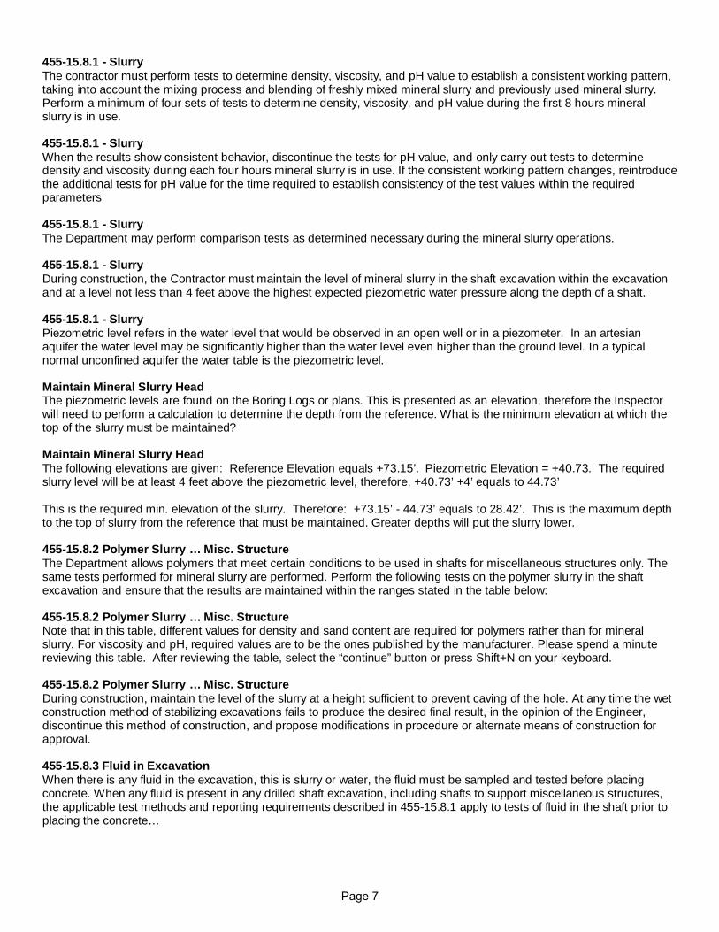
455-15.8.1 - Slurry The contractor must perform tests to determine density, viscosity, and pH value to establish a consistent working pattern, taking into account the mixing process and blending of freshly mixed mineral slurry and previously used mineral slurry. Perform a minimum of four sets of tests to determine density, viscosity, and pH value during the first 8 hours mineral slurry is in use. 455-15.8.1 - Slurry When the results show consistent behavior, discontinue the tests for pH value, and only carry out tests to determine density and viscosity during each four hours mineral slurry is in use. If the consistent working pattern changes, reintroduce the additional tests for pH value for the time required to establish consistency of the test values within the required parameters 455-15.8.1 - Slurry The Department may perform comparison tests as determined necessary during the mineral slurry operations. 455-15.8.1 - Slurry During construction, the Contractor must maintain the level of mineral slurry in the shaft excavation within the excavation and at a level not less than 4 feet above the highest expected piezometric water pressure along the depth of a shaft. 455-15.8.1 - Slurry Piezometric level refers in the water level that would be observed in an open well or in a piezometer. In an artesian aquifer the water level may be significantly higher than the water level even higher than the ground level. In a typical normal unconfined aquifer the water table is the piezometric level. Maintain Mineral Slurry Head The piezometric levels are found on the Boring Logs or plans. This is presented as an elevation, therefore the Inspector will need to perform a calculation to determine the depth from the reference. What is the minimum elevation at which the top of the slurry must be maintained? Maintain Mineral Slurry Head The following elevations are given: Reference Elevation equals +73.15’. Piezometric Elevation = +40.73. The required slurry level will be at least 4 feet above the piezometric level, therefore, +40.73’ +4’ equals to 44.73’ This is the required min. elevation of the slurry. Therefore: +73.15’ - 44.73’ equals to 28.42’. This is the maximum depth to the top of slurry from the reference that must be maintained. Greater depths will put the slurry lower. 455-15.8.2 Polymer Slurry … Misc. Structure The Department allows polymers that meet certain conditions to be used in shafts for miscellaneous structures only. The same tests performed for mineral slurry are performed. Perform the following tests on the polymer slurry in the shaft excavation and ensure that the results are maintained within the ranges stated in the table below: 455-15.8.2 Polymer Slurry … Misc. Structure Note that in this table, different values for density and sand content are required for polymers rather than for mineral slurry. For viscosity and pH, required values are to be the ones published by the manufacturer. Please spend a minute reviewing this table. After reviewing the table, select the “continue” button or press Shift+N on your keyboard. 455-15.8.2 Polymer Slurry … Misc. Structure During construction, maintain the level of the slurry at a height sufficient to prevent caving of the hole. At any time the wet construction method of stabilizing excavations fails to produce the desired final result, in the opinion of the Engineer, discontinue this method of construction, and propose modifications in procedure or alternate means of construction for approval. 455-15.8.3 Fluid in Excavation When there is any fluid in the excavation, this is slurry or water, the fluid must be sampled and tested before placing concrete. When any fluid is present in any drilled shaft excavation, including shafts to support miscellaneous structures, the applicable test methods and reporting requirements described in 455-15.8.1 apply to tests of fluid in the shaft prior to placing the concrete…
Page 7
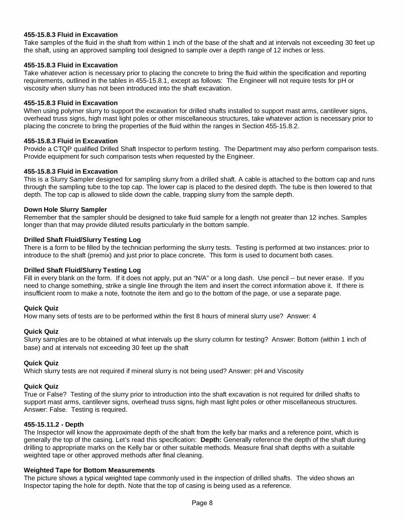
455-15.8.3 Fluid in Excavation Take samples of the fluid in the shaft from within 1 inch of the base of the shaft and at intervals not exceeding 30 feet up the shaft, using an approved sampling tool designed to sample over a depth range of 12 inches or less. 455-15.8.3 Fluid in Excavation Take whatever action is necessary prior to placing the concrete to bring the fluid within the specification and reporting requirements, outlined in the tables in 455-15.8.1, except as follows: The Engineer will not require tests for pH or viscosity when slurry has not been introduced into the shaft excavation. 455-15.8.3 Fluid in Excavation When using polymer slurry to support the excavation for drilled shafts installed to support mast arms, cantilever signs, overhead truss signs, high mast light poles or other miscellaneous structures, take whatever action is necessary prior to placing the concrete to bring the properties of the fluid within the ranges in Section 455-15.8.2. 455-15.8.3 Fluid in Excavation Provide a CTQP qualified Drilled Shaft Inspector to perform testing. The Department may also perform comparison tests. Provide equipment for such comparison tests when requested by the Engineer. 455-15.8.3 Fluid in Excavation This is a Slurry Sampler designed for sampling slurry from a drilled shaft. A cable is attached to the bottom cap and runs through the sampling tube to the top cap. The lower cap is placed to the desired depth. The tube is then lowered to that depth. The top cap is allowed to slide down the cable, trapping slurry from the sample depth. Down Hole Slurry Sampler Remember that the sampler should be designed to take fluid sample for a length not greater than 12 inches. Samples longer than that may provide diluted results particularly in the bottom sample. Drilled Shaft Fluid/Slurry Testing Log There is a form to be filled by the technician performing the slurry tests. Testing is performed at two instances: prior to introduce to the shaft (premix) and just prior to place concrete. This form is used to document both cases. Drilled Shaft Fluid/Slurry Testing Log Fill in every blank on the form. If it does not apply, put an “N/A” or a long dash. Use pencil -- but never erase. If you need to change something, strike a single line through the item and insert the correct information above it. If there is insufficient room to make a note, footnote the item and go to the bottom of the page, or use a separate page. Quick Quiz How many sets of tests are to be performed within the first 8 hours of mineral slurry use? Answer: 4 Quick Quiz Slurry samples are to be obtained at what intervals up the slurry column for testing? Answer: Bottom (within 1 inch of base) and at intervals not exceeding 30 feet up the shaft Quick Quiz Which slurry tests are not required if mineral slurry is not being used? Answer: pH and Viscosity Quick Quiz True or False? Testing of the slurry prior to introduction into the shaft excavation is not required for drilled shafts to support mast arms, cantilever signs, overhead truss signs, high mast light poles or other miscellaneous structures. Answer: False. Testing is required. 455-15.11.2 - Depth The Inspector will know the approximate depth of the shaft from the kelly bar marks and a reference point, which is generally the top of the casing. Let’s read this specification: Depth: Generally reference the depth of the shaft during drilling to appropriate marks on the Kelly bar or other suitable methods. Measure final shaft depths with a suitable weighted tape or other approved methods after final cleaning. Weighted Tape for Bottom Measurements The picture shows a typical weighted tape commonly used in the inspection of drilled shafts. The video shows an Inspector taping the hole for depth. Note that the top of casing is being used as a reference.
Page 8
Shaft Inspection This photograph shows an Inspector measuring a shaft with a weighted tape. Note that he uses the top of the casing as the reference elevation. Shaft Inspection Shafts depths are determined by:
• Lowering a weighted tape down to the bottom of the shaft after cleaning, or the Contractor’s marks on the kelly. • Typically measured and recorded to the nearest 0.01 foot from the supplied reference.
Check specifications for degree of accuracy, Weighted Tape for Bottom Measurements This video shows an Inspector taping the hole for depth. Note that the top of casing is being used as a reference. Weighted Tape for Bottom Measurements Pictured here is a shaft sounding device called by the manufacturer as DID, an acronym for Ding Inspection Device. This device measures the thickness of sediments at local points using a strain gage. The measurements appear digitally in an electronic transducer. The other picture shows a technician is taking the sediment thickness readings with this device. The Department is currently testing this device and considering its use statewide in the near future. 455-15.11.4 – Shaft Cleanliness Requirement Shaft Cleanliness Requirements: Adjust cleaning operations so a minimum of 50% of the bottom of each shaft will have less than 1/2 inch of sediment at the time of placement of the concrete. 455-15.11.4 – Shaft Cleanliness Requirement Ensure the maximum depth of sedimentary deposits or any other debris at any place on the bottom of the shaft excavation does not exceed 1 1/2 inches. The Engineer will determine shaft cleanliness by visual inspection for dry shafts, using divers or an inspection device or other methods the Engineer deems appropriate for wet shafts. When using slurry, meet the requirements of 455-15.8 at the time of concrete placement. Checking Shaft Bottom for Cleanliness This illustration shows how to measure for the sediment thickness in the shaft. One of the most common methods to measure sediment on the bottom of the shaft is through the use of a weighted tape. – Checking Shaft Bottom for Cleanliness Following removal of the drilling tool, lower a weighted tape slowly down the hole until encountering the sediment or bottom. Take and record the measurement. Compare that measurement with the depth of the tape when it encounters a firm bottom which would be the depth of the shaft. The difference between these measurements is the thickness of sediment on the shaft bottom. Checking Shaft Bottom for Cleanliness Repeat this at five locations or more around the shaft. By doing 5 (or more) soundings around the shaft, the Inspector has accumulated sufficient data to document compliance with both of the specified dimensions. Larger shafts may require more locations. 455-15.11.4.1 – Exceptions…Misc. Shafts For shafts for miscellaneous structures the cleanliness specification is different. Ensure the depth of sedimentary deposits or other debris does not exceed 1 inch over the bottom of the shaft when installing drilled shafts to support mast arms, cantilever signs, overhead truss signs, high mast light poles or other miscellaneous structures. 455-15.11.5 – time of excavation Any unclassified excavation work lasting more than 36 hours (measured from the beginning of excavation for all methods except the Permanent Casing Method, which begins at the time excavation begins below the casing) before placement of the concrete requires over reaming the sidewalls to the depth of softening or removing excessive slurry cake buildup as indicated by samples taken by the sidewall sampler or other test methods employed by the Engineer. 455-15.11.5 – time of excavation If the shaft remains open too long, many things can happen, none of them good. Over reaming is the removal of slurry cake buildup and softened sides of the shaft. Failure to over ream when needed can result in loss of some skin friction the designer was counting on.
Page 9
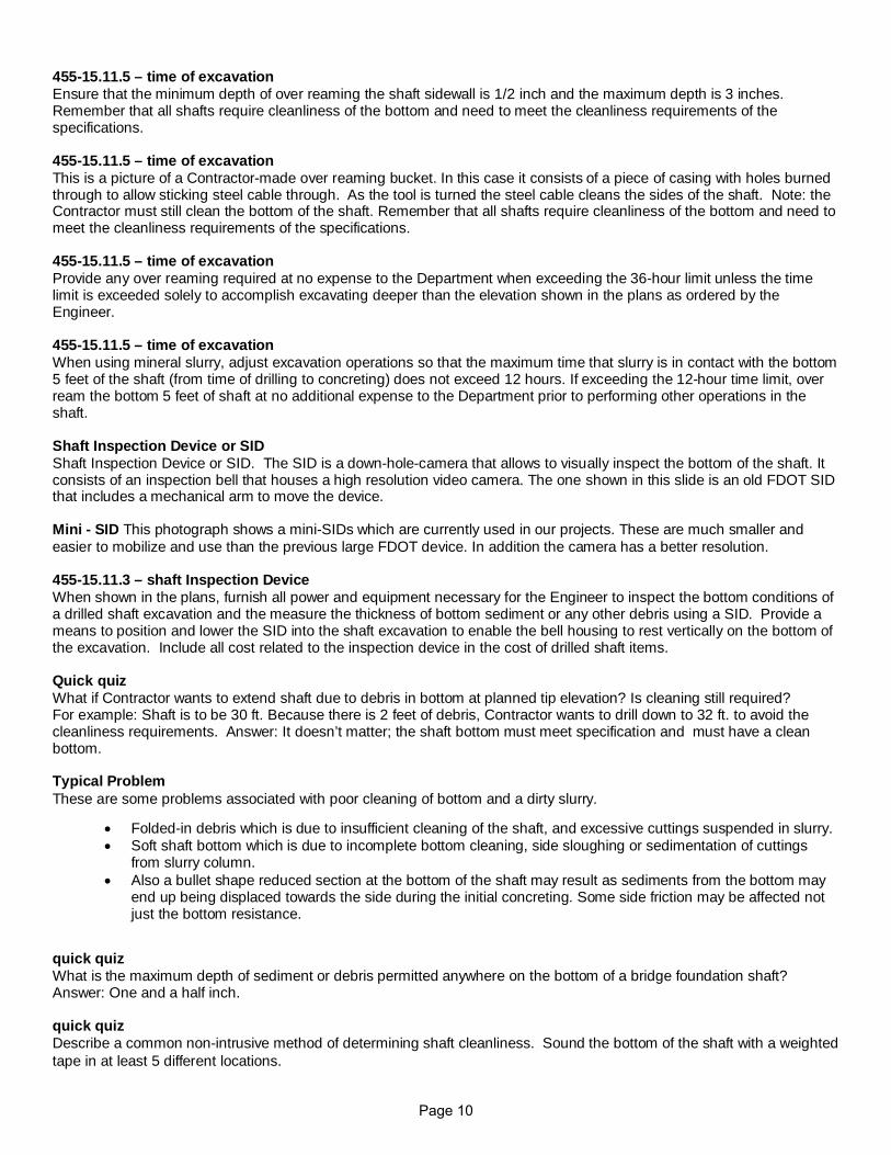
455-15.11.5 – time of excavation Ensure that the minimum depth of over reaming the shaft sidewall is 1/2 inch and the maximum depth is 3 inches. Remember that all shafts require cleanliness of the bottom and need to meet the cleanliness requirements of the specifications. 455-15.11.5 – time of excavation This is a picture of a Contractor-made over reaming bucket. In this case it consists of a piece of casing with holes burned through to allow sticking steel cable through. As the tool is turned the steel cable cleans the sides of the shaft. Note: the Contractor must still clean the bottom of the shaft. Remember that all shafts require cleanliness of the bottom and need to meet the cleanliness requirements of the specifications. 455-15.11.5 – time of excavation Provide any over reaming required at no expense to the Department when exceeding the 36-hour limit unless the time limit is exceeded solely to accomplish excavating deeper than the elevation shown in the plans as ordered by the Engineer. 455-15.11.5 – time of excavation When using mineral slurry, adjust excavation operations so that the maximum time that slurry is in contact with the bottom 5 feet of the shaft (from time of drilling to concreting) does not exceed 12 hours. If exceeding the 12-hour time limit, over ream the bottom 5 feet of shaft at no additional expense to the Department prior to performing other operations in the shaft. Shaft Inspection Device or SID Shaft Inspection Device or SID. The SID is a down-hole-camera that allows to visually inspect the bottom of the shaft. It consists of an inspection bell that houses a high resolution video camera. The one shown in this slide is an old FDOT SID that includes a mechanical arm to move the device. Mini - SID This photograph shows a mini-SIDs which are currently used in our projects. These are much smaller and easier to mobilize and use than the previous large FDOT device. In addition the camera has a better resolution. 455-15.11.3 – shaft Inspection Device When shown in the plans, furnish all power and equipment necessary for the Engineer to inspect the bottom conditions of a drilled shaft excavation and the measure the thickness of bottom sediment or any other debris using a SID. Provide a means to position and lower the SID into the shaft excavation to enable the bell housing to rest vertically on the bottom of the excavation. Include all cost related to the inspection device in the cost of drilled shaft items. Quick quiz What if Contractor wants to extend shaft due to debris in bottom at planned tip elevation? Is cleaning still required? For example: Shaft is to be 30 ft. Because there is 2 feet of debris, Contractor wants to drill down to 32 ft. to avoid the cleanliness requirements. Answer: It doesn’t matter; the shaft bottom must meet specification and must have a clean bottom. Typical Problem These are some problems associated with poor cleaning of bottom and a dirty slurry.
• Folded-in debris which is due to insufficient cleaning of the shaft, and excessive cuttings suspended in slurry. • Soft shaft bottom which is due to incomplete bottom cleaning, side sloughing or sedimentation of cuttings
from slurry column. • Also a bullet shape reduced section at the bottom of the shaft may result as sediments from the bottom may
end up being displaced towards the side during the initial concreting. Some side friction may be affected not just the bottom resistance.
quick quiz What is the maximum depth of sediment or debris permitted anywhere on the bottom of a bridge foundation shaft? Answer: One and a half inch. quick quiz Describe a common non-intrusive method of determining shaft cleanliness. Sound the bottom of the shaft with a weighted tape in at least 5 different locations.
Page 10
Drilled Shaft Log We will go over the Drilled Shaft Log form, Form number 700-010-84. This form is used to record the events observed during the excavation process. The log consists of two pages. They are available in pdf and excel formats. In the pdf formats the inspector needs to compute the data of the field highlighted in yellow. In the excel format these fields are computed automatically. Drilled Shaft Log The form contains two pages. These can be accessed in the spreadsheet by clicking the tabs at the bottom. To better follow these instructions we suggest you have a copy of each of the two pages with you. The link to the Drilled Shaft Log can be found on the resources page. Drilled Shaft Log Let’s take a look at the different sections of the form. Drilled Shaft Log Section 1 consists of the heading with the following basic information: Project name, Financial project number, Contractor’s name, Inspector’s name, dates, pier number, shaft number, stations and offsets and the bridge or structure number. This information may be filled in before the drilling starts. Be sure to print your name & the start date of drilling or casing installation. The Project Administrator or permit manager will sign the approval line. Drilled Shaft Log The form allows the input of up to two casings (one outside and one inside). The inside casing may be segmental. The form allows the use of up to 5 segmental sections in the interior casing. The figure at the right side illustrates the casing sections for the input of this part of the form. Drilled Shaft Log When using the excel spreadsheet, the yellow fields are formulas and you cannot enter anything on them. Type could be either permanent or temporary. ID, OD are the inside and outside diameters of the casings Drilled Shaft Log For the outside casing you input the total length of the casing used. For the interior segmental casing you enter the individual segment lengths. The spreadsheet will compute the total length of the segments of the interior casing, and the bottom elevation of both casings. Drilled Shaft Log If there is no segments but only one section just enter one section under the top section column. Do not enter it under the collar column as it produces redundant information. Even though the information shown is correct it may be confusing for a reader. Drilled Shaft Log Section 3: Enter Dates of casing installation, dates of excavation and the date of pouring. Section 4: Enter the initial reference elevations. Indicate ground surface elevation, water table and the shaft top elevations, both per plans and the “as built” elevation. The drilled shaft bottom elevation is determined after the average shaft bottom elevation is calculated in page 2. We will look into page 2 in a moment. Drilled Shaft Log Section 5: Enter auger diameter used in inches. Enter rock socket diameter, rock socket length achieved in the shaft, and actual shaft diameters. Indicate whether the shaft was over reamed. The constructed shaft length is calculated from the actual shaft top elevation and the drilled shaft bottom elevation input in section 4. Drilled Shaft Log Section 6: Enter the computed theoretical volume and actual volume of concrete placed and the ratio Actual over theoretical volumes A over T. This will be input after concrete is completed. Drilled Shaft Log This is the main body of the log where you will document the materials encountered. We will cover the sections of this area: Section 7: Enter Depth. Depth can be measured by either: Contractor Kelly bar marks or The use of a Weighted tape.
Page 11
Drilled Shaft Log Section 8: Enter times whenever tools go in and come out of hole. Be sure to input the AM and PM after the hour, or use military times based on 24 hours. Drilled Shaft Log Section 9: Enter reference elevation. In the spreadsheet, if there are no changes you can just copy and paste the input down the column. This input is used to compute the elevations of the bottom of the shaft as the excavation progresses. Elevations in the yellow column, are calculated based on the reference elevation and the depth. In the spreadsheet this occurs automatically. Drilled Shaft Log Section 10: Accurately describe soil and rock materials observed from the drilled shaft excavation. Enter any pertinent Notes regarding events observed during the excavation (example: loss of slurry, setting more casing, etc.) Drilled Shaft Log This is page 2 of the form. On the left side, it contains a continuation of the sections 7 to 10 already covered when we saw the first page. We use these columns to keep inputting deeper information of the materials observed during excavation and pertinent notes of events observed. In deep shafts it may be required to use this page 2 more than once until completing the full depth of the shaft. We also use this page to record the bottom cleanliness and depth information. Drilled Shaft Log We will cover now the sections at the right side of this page. Section 11: This is a quick checklist to document whether the rebar details were checked. Section 12: Indicate here what tools were used in the clean out operation. Drilled Shaft Log Section 13: Enter here the date and time of the clean out completion. Section 14: Indicate here the method used to perform the bottom cleanliness inspection. Enter also the reference elevation to be used to compute the final tip elevation. Drilled Shaft Log Section 15: Enter the sediment thickness and depth of the shaft at each of the points indicated. The next slide illustrates a detail of this section. Enter also the starting and finishing times of the bottom inspection. Drilled Shaft Log Here we see a detail of a sample of section 15 of page 2. Input the information measured at each point. Depth is input at the top of the line in feet. Sediment thickness is input below the line in inches. For example, in point 5 of the example, the depth is 90.2 feet and the sediment is 0.3 inches thick. Drilled Shaft Log The yellow fields are for the average shaft bottom elevation and the average shaft depth. These are computed based on the 5 points measured above and the reference elevation entered here. In the spreadsheet these are automatically computed and you cannot input data on them. The average shaft bottom elevation is also used in part 4 of page 1 as we saw earlier. This is the end of the instructions for the Drilled Shaft log. Drilled Shaft Log In this lesson we have covered the following:
• Perform inspection of drilled shaft excavations for compliance to plans, tolerances and cleanliness. • Perform visual field verification of soil/rock material for comparison to supplied soil boring data/logs. • Sample and test slurry and fluid in the excavation. • Calculate Elevations & Extra Shaft Lengths. • Identify the applicable 455 Specifications
End of Lesson This is the end of lesson 6. Please select the next lesson button on this page to continue to the next lesson.