Page 1
Subject: Electronics, Programming Grade Levels: 9th-12th
Prepared By: Md. Khairul Alam
Lesson Plan: Digital Alarm Clock Using Arduino Learner Kit
Overview:
This lesson use Arduino Learner Kit to make a digital alarm clock. Arduino Learner Kit has
onboard DS1307 RTC, Buzzer, Button Switch and LCD display which will be used to make the
alarm clock. Students need to connect all the components to Arduino using jumper wires. After
making the connection they will write code and upload it the Arduino Kit.
After completing the lesson students will learn:
About I2C communication protocol and how to implement I2C using Arduino
About interfacing of DS1307 RTC and LCD Display
About generating tone using Arduino and Buzzer
How to use external library in Arduino IDE.
How to apply conditional statements and loops in a program.
Perquisites:
Basic knowledge on Arduino digital output (e.g. how to drive led)
Basic knowledge on Arduino digital input (e.g. how the interface button switch)
Important Questions:
What are the different communication protocol use in embedded system?
Difference between serial and parallel communication?
What are the most common serial protocol used in Arduino?
Why RTC is used in microcontroller system?
[Teacher will ask students and explain the answer of the questions]
Materials needed:
1 Arduino Learner Kit with USB cable
12 male to male jumper wires
2 male to female jumper wire
Access to a PC
Page 2
Subject: Electronics, Programming Grade Levels: 9th-12th
Prepared By: Md. Khairul Alam
Background Knowledge:
I2C Serial Communication:
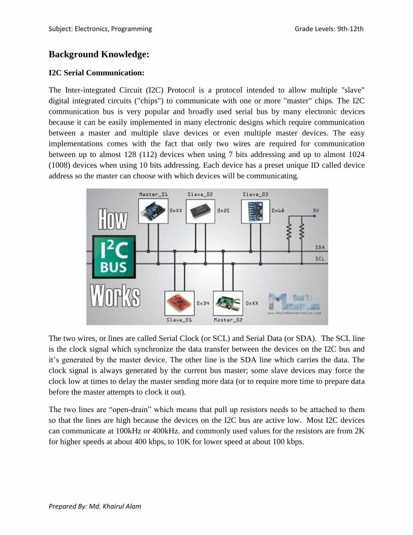
The Inter-integrated Circuit (I2C) Protocol is a protocol intended to allow multiple "slave"
digital integrated circuits ("chips") to communicate with one or more "master" chips. The I2C
communication bus is very popular and broadly used serial bus by many electronic devices
because it can be easily implemented in many electronic designs which require communication
between a master and multiple slave devices or even multiple master devices. The easy
implementations comes with the fact that only two wires are required for communication
between up to almost 128 (112) devices when using 7 bits addressing and up to almost 1024
(1008) devices when using 10 bits addressing. Each device has a preset unique ID called device
address so the master can choose with which devices will be communicating.
The two wires, or lines are called Serial Clock (or SCL) and Serial Data (or SDA). The SCL line
is the clock signal which synchronize the data transfer between the devices on the I2C bus and
it’s generated by the master device. The other line is the SDA line which carries the data. The
clock signal is always generated by the current bus master; some slave devices may force the
clock low at times to delay the master sending more data (or to require more time to prepare data
before the master attempts to clock it out).
The two lines are “open-drain” which means that pull up resistors needs to be attached to them
so that the lines are high because the devices on the I2C bus are active low. Most I2C devices
can communicate at 100kHz or 400kHz. and commonly used values for the resistors are from 2K
for higher speeds at about 400 kbps, to 10K for lower speed at about 100 kbps.
Page 3
Subject: Electronics, Programming Grade Levels: 9th-12th
Prepared By: Md. Khairul Alam
The Protocol:
Communication via I2C is more complex than with a UART or SPI solution. The signalling must
adhere to a certain protocol for the devices on the bus to recognize it as valid I2C
communications. Fortunately, most devices take care of all the fiddly details for you, allowing
you to concentrate on the data you wish to exchange.
Basics
Messages are broken up into two types of frame: an address frame, where the master indicates
the slave to which the message is being sent, and one or more data frames, which are 8-bit data
messages passed from master to slave or vice versa. Data is placed on the SDA line after SCL
goes low, and is sampled after the SCL line goes high. The time between clock edge and data
read/write is defined by the devices on the bus and will vary from chip to chip.
Start Condition
To initiate the address frame, the master device leaves SCL high and pulls SDA low. This puts
all slave devices on notice that a transmission is about to start. If two master devices wish to take
ownership of the bus at one time, whichever device pulls SDA low first wins the race and gains
control of the bus. It is possible to issue repeated starts, initiating a new communication sequence
without relinquishing control of the bus to other masters; we'll talk about that later.
Address Frame
The address frame is always first in any new communication sequence. For a 7-bit address, the
address is clocked out most significant bit (MSB) first, followed by a R/W bit indicating whether
this is a read (1) or write (0) operation.
The 9th bit of the frame is the NACK/ACK bit. This is the case for all frames (data or address).
Once the first 8 bits of the frame are sent, the receiving device is given control over SDA. If the
receiving device does not pull the SDA line low before the 9th clock pulse, it can be inferred that
the receiving device either did not receive the data or did not know how to parse the message. In
that case, the exchange halts, and it's up to the master of the system to decide how to proceed.
Page 4
Subject: Electronics, Programming Grade Levels: 9th-12th
Prepared By: Md. Khairul Alam
Data Frames
After the address frame has been sent, data can begin being transmitted. The master will simply
continue generating clock pulses at a regular interval, and the data will be placed on SDA by
either the master or the slave, depending on whether the R/W bit indicated a read or write
operation. The number of data frames is arbitrary, and most slave devices will auto-increment the
internal register, meaning that subsequent reads or writes will come from the next register in line.
Stop condition
Once all the data frames have been sent, the master will generate a stop condition. Stop
conditions are defined by a 0->1 (low to high) transition on SDA after a 0->1 transition on SCL,
with SCL remaining high. During normal data writing operation, the value on SDA
should not change when SCL is high, to avoid false stop conditions.
The DS1307 RTC:
Real time clocks (RTC), as the name recommends are clock modules. RTC is a system that keeps
track of the current time and can be used in any device which needs to keep accurate time even
after power failure. DS1307 module is one of the most affordable and common RTCs modules. It
can accurately keep track of seconds, minutes, hours, days, months, and years. The DS1307 real
time clock (RTC) IC is an 8 pin device using an I2C interface. The DS1307 is a low-power
clock/calendar with 56 bytes of battery backup SRAM. The clock/calendar provides seconds,
minutes, hours, day, date, month and year qualified data. The end date of each month is
automatically adjusted, especially for months with less than 31 days.
The main advantage of RTC is that they have an arrangement of battery backup which keeps the
clock/calendar running even if there is power failure. An exceptionally little current is required
for keeping the RTC animated. We can find these RTCs in many applications like embedded
systems and computer mother boards, etc. In this article we are going to see about one of the real
time clock (RTC), i.e. DS1307. The DS1307 module has the capability to install a 3-volt
CR2023 backup battery and use a 32.768 kHz crystal oscillator.
Page 5
Subject: Electronics, Programming Grade Levels: 9th-12th
Prepared By: Md. Khairul Alam
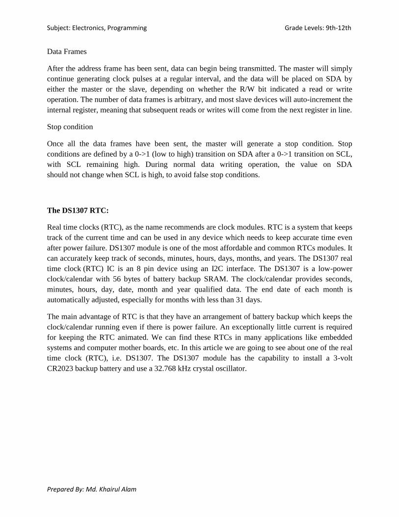
Pin-out and Connections:
The DS1307 RTC module has total 8 pins
that interface it to the outside world. In the
simple circuit the two inputs X1 and X2 are
connected to a 32.768 kHz crystal oscillator
as the source for the chip. VBAT is
connected to positive terminal of a 3V
battery chip. Vcc provides power to the I2C
interface and 5V can be given using
microcontrollers. The data communication
with Arduino is performed using SCL and
SDA pin. These two pin must be pull up
with 4.7KΩ resistor.
Table 1: Connection with Arduino
LM35 Arduino
VCC 5V
SCL A5
SDA A4
GND GND
The LCD Display:
LCD (Liquid Crystal Display) is very popular and broadly used in electronics projects as they are
good for displaying information like sensors data from your project, and also they are very
cheap.
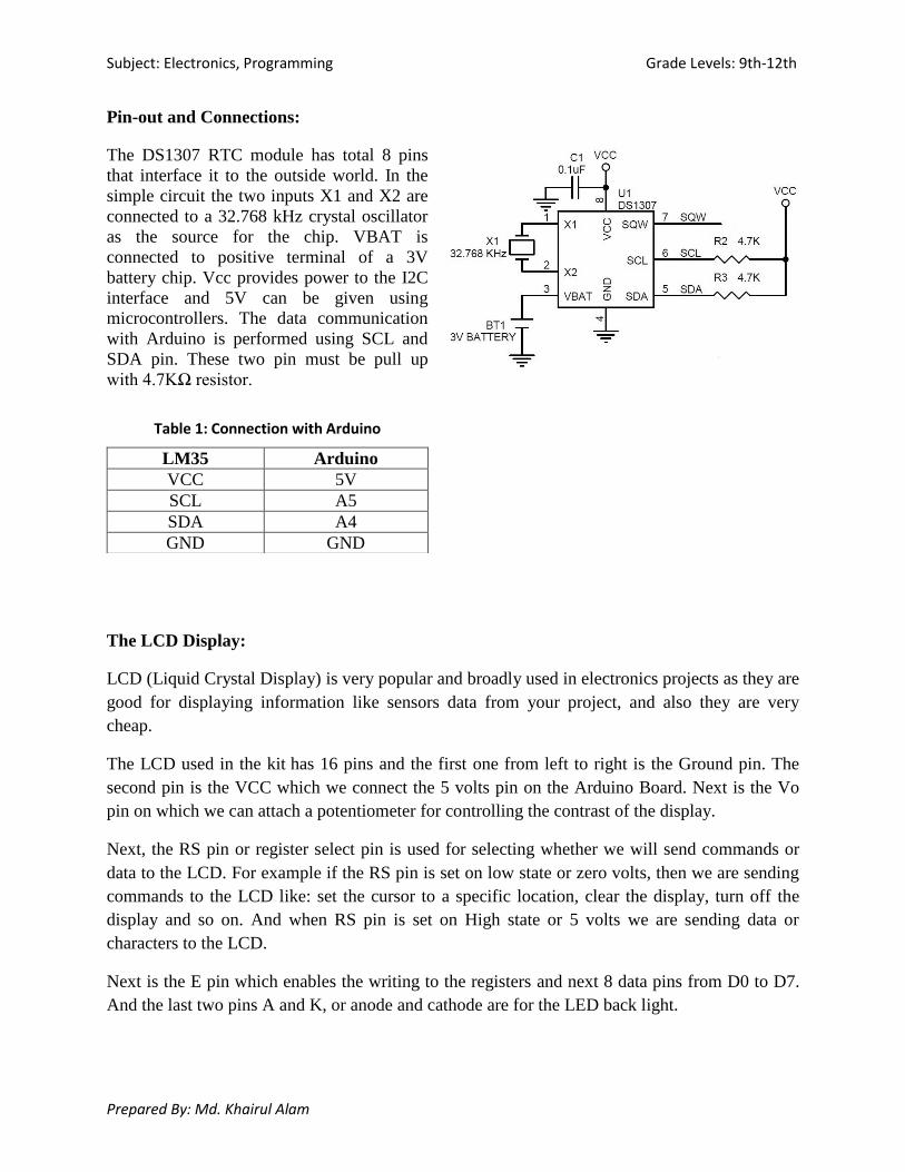
The LCD used in the kit has 16 pins and the first one from left to right is the Ground pin. The
second pin is the VCC which we connect the 5 volts pin on the Arduino Board. Next is the Vo
pin on which we can attach a potentiometer for controlling the contrast of the display.
Next, the RS pin or register select pin is used for selecting whether we will send commands or
data to the LCD. For example if the RS pin is set on low state or zero volts, then we are sending
commands to the LCD like: set the cursor to a specific location, clear the display, turn off the
display and so on. And when RS pin is set on High state or 5 volts we are sending data or
characters to the LCD.
Next is the E pin which enables the writing to the registers and next 8 data pins from D0 to D7.
And the last two pins A and K, or anode and cathode are for the LED back light.
Page 6
Subject: Electronics, Programming Grade Levels: 9th-12th
Prepared By: Md. Khairul Alam
The display can work both 4 bit mode and 8 bit mode. We need to connect D4-D7 to Arduino to
work in 4 bit mode. D0-D3 should be unconnected. In the kit GND, VCC, Vo, A, K are already
connected to appropriate source. You need to make the following connection only:
Table 2: LCD and Arduino Connection
LCD Arduino
RS 9
E 8
D4 4
D5 5
D6 6
D7 7
Recommended Procedure:
1. Connect B_CONN (buzzer) pin to D11 pin of the Arduino using a male to female jumper
wire.
2. Connect the LCD pins to the Arduino pins according to the table 2 using male to male
jumper wires.
3. Connect S1, S2, S3 and S4 pins to A0, A1, A2 and A3 pins of Arduino header
respectively .
4. Connect SCL pin to A5 pin of Arduino header and SDA pin to A4 pin of the Arduino
header.
5. Open Arduino IDE and copy the provided code in a new sketch and save it.
6. Connect the kit to PC using a the USB cable and upload the provided sketch to the kit.
7. You will see the time and date in the display.
8. Use the buttons to adjust the date and time of the clock.
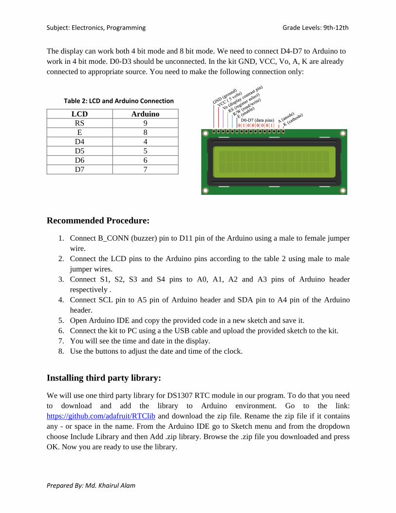
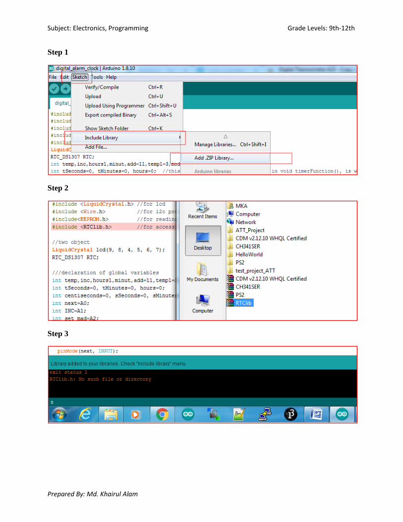
Installing third party library:
We will use one third party library for DS1307 RTC module in our program. To do that you need
to download and add the library to Arduino environment. Go to the link:
https://github.com/adafruit/RTClib and download the zip file. Rename the zip file if it contains
any - or space in the name. From the Arduino IDE go to Sketch menu and from the dropdown
choose Include Library and then Add .zip library. Browse the .zip file you downloaded and press
OK. Now you are ready to use the library.
Page 7
Subject: Electronics, Programming Grade Levels: 9th-12th
Prepared By: Md. Khairul Alam
Step 1
Step 2
Step 3
Page 8
Subject: Electronics, Programming Grade Levels: 9th-12th
Prepared By: Md. Khairul Alam
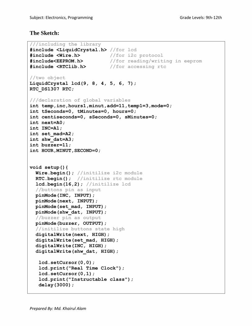
The Sketch:
///including the library
#include <LiquidCrystal.h> //for lcd
#include <Wire.h> //for i2c protocol
#include<EEPROM.h> //for reading/writing in eeprom
#include <RTClib.h> //for accessing rtc
//two object
LiquidCrystal lcd(9, 8, 4, 5, 6, 7);
RTC_DS1307 RTC;
///declaration of global variables
int temp,inc,hours1,minut,add=11,temp1=3,mode=0;
int tSeconds=0, tMinutes=0, hours=0;
int centiseconds=0, sSeconds=0, sMinutes=0;
int next=A0;
int INC=A1;
int set_mad=A2;
int shw_dat=A3;
int buzzer=11;
int HOUR,MINUT,SECOND=0;
void setup()
Wire.begin(); //initilize i2c module
RTC.begin(); //initilize rtc module
lcd.begin(16,2); //initilize lcd
//buttons pin as input
pinMode(INC, INPUT);
pinMode(next, INPUT);
pinMode(set_mad, INPUT);
pinMode(shw_dat, INPUT);
//buzzer pin as output
pinMode(buzzer, OUTPUT);
//initilize buttons state high
digitalWrite(next, HIGH);
digitalWrite(set_mad, HIGH);
digitalWrite(INC, HIGH);
digitalWrite(shw_dat, HIGH);
lcd.setCursor(0,0);
lcd.print("Real Time Clock");
lcd.setCursor(0,1);
lcd.print("Instructable class");
delay(3000);
Page 9
Subject: Electronics, Programming Grade Levels: 9th-12th
Prepared By: Md. Khairul Alam
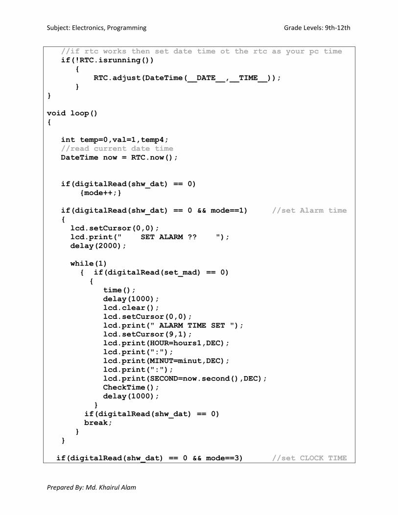
//if rtc works then set date time ot the rtc as your pc time
if(!RTC.isrunning())
RTC.adjust(DateTime(__DATE__,__TIME__));
void loop()
int temp=0,val=1,temp4;
//read current date time
DateTime now = RTC.now();
if(digitalRead(shw_dat) == 0)
mode++;
if(digitalRead(shw_dat) == 0 && mode==1) //set Alarm time
lcd.setCursor(0,0);
lcd.print(" SET ALARM ?? ");
delay(2000);
while(1)
if(digitalRead(set_mad) == 0)
time();
delay(1000);
lcd.clear();
lcd.setCursor(0,0);
lcd.print(" ALARM TIME SET ");
lcd.setCursor(9,1);
lcd.print(HOUR=hours1,DEC);
lcd.print(":");
lcd.print(MINUT=minut,DEC);
lcd.print(":");
lcd.print(SECOND=now.second(),DEC);
CheckTime();
delay(1000);
if(digitalRead(shw_dat) == 0)
break;
if(digitalRead(shw_dat) == 0 && mode==3) //set CLOCK TIME
Page 10
Subject: Electronics, Programming Grade Levels: 9th-12th
Prepared By: Md. Khairul Alam
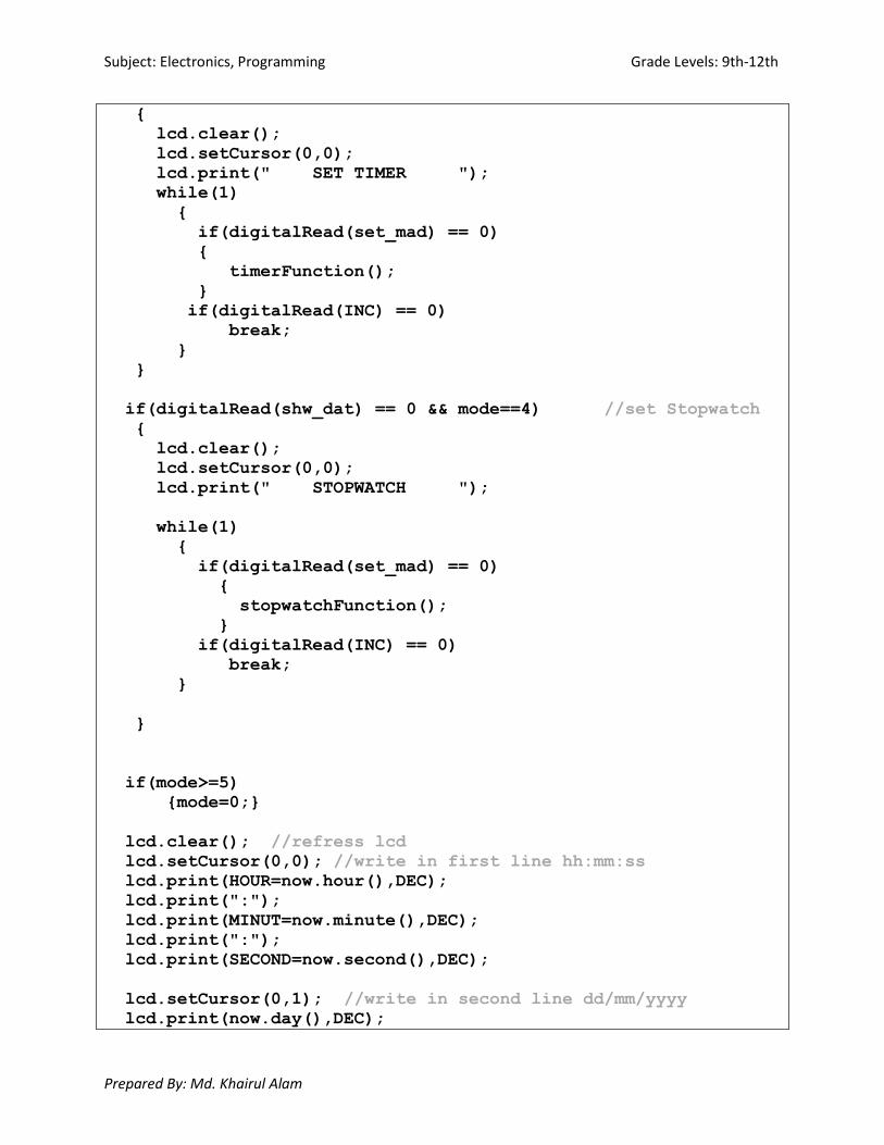
lcd.clear();
lcd.setCursor(0,0);
lcd.print(" SET TIMER ");
while(1)
if(digitalRead(set_mad) == 0)
timerFunction();
if(digitalRead(INC) == 0)
break;
if(digitalRead(shw_dat) == 0 && mode==4) //set Stopwatch
lcd.clear();
lcd.setCursor(0,0);
lcd.print(" STOPWATCH ");
while(1)
if(digitalRead(set_mad) == 0)
stopwatchFunction();
if(digitalRead(INC) == 0)
break;
if(mode>=5)
mode=0;
lcd.clear(); //refress lcd
lcd.setCursor(0,0); //write in first line hh:mm:ss
lcd.print(HOUR=now.hour(),DEC);
lcd.print(":");
lcd.print(MINUT=now.minute(),DEC);
lcd.print(":");
lcd.print(SECOND=now.second(),DEC);
lcd.setCursor(0,1); //write in second line dd/mm/yyyy
lcd.print(now.day(),DEC);
Page 11
Subject: Electronics, Programming Grade Levels: 9th-12th
Prepared By: Md. Khairul Alam
lcd.print("/");
lcd.print(now.month(),DEC);
lcd.print("/");
lcd.print(now.year(),DEC);
delay(1000); //wait some time
/*Function to set alarm time and feed time into Internal
eeprom*/
void time()
int temp=1,minuts=0,hours=0,seconds=0;
while(temp==1)
if(digitalRead(INC)==0)
HOUR++;
if(HOUR==24)
HOUR=0;
while(digitalRead(INC)==0);
lcd.clear();
lcd.setCursor(0,0);
lcd.print("Set Alarm Time ");
lcd.setCursor(0,1);
lcd.print(HOUR);
lcd.print(":");
lcd.print(MINUT);
lcd.print(":");
lcd.print(SECOND);
delay(100);
if(digitalRead(next)==0)
hours1=HOUR;
EEPROM.write(add++,hours1);
temp=2;
while(digitalRead(next)==0);
while(temp==2)
if(digitalRead(INC)==0)
Page 12
Subject: Electronics, Programming Grade Levels: 9th-12th
Prepared By: Md. Khairul Alam
MINUT++;
if(MINUT==60)
MINUT=0;
while(digitalRead(INC)==0);
lcd.setCursor(0,1);
lcd.print(HOUR);
lcd.print(":");
lcd.print(MINUT);
lcd.print(":");
lcd.print(SECOND);
delay(100);
if(digitalRead(next)==0)
minut=MINUT;
EEPROM.write(add++, minut);
temp=0;
while(digitalRead(next)==0);
delay(1000);
/* Function to chack medication time */
void CheckTime()
int tem[17];
while(1)
DateTime now = RTC.now();
lcd.setCursor(0,1);
lcd.print(HOUR=now.hour(),DEC);
lcd.print(":");
lcd.print(MINUT=now.minute(),DEC);
lcd.print(":");
lcd.print(SECOND=now.second(),DEC);
for(int i=11;i<17;i++)
tem[i]=EEPROM.read(i);
if(HOUR == tem[11] && MINUT == tem[12])
for(int j=0;j<5;j++)
digitalWrite(buzzer, HIGH);
delay(500);
digitalWrite(buzzer, LOW);
Page 13
Subject: Electronics, Programming Grade Levels: 9th-12th
Prepared By: Md. Khairul Alam
delay(500);
hours1=0;
minut=0;
add=11;
return;
void timerFunction() //the timer function was made with the
//help of this post: http://pastebin.com/f57045830
int set=0;
lcd.setCursor(4,1);
lcd.print("00:00:00");
while(1)
while(digitalRead(shw_dat)==1)
set=1;
if(digitalRead(set_mad)==0) //if
//"Start/Stop" is pressed, the timer counts down
tSeconds++;
lcdOutput();
delay(300);
if(tSeconds==60)
tMinutes++;
tSeconds=0;
if(digitalRead(INC)==0) //if "Start/Stop" is
//pressed, the timer counts down
tMinutes++;
lcdOutput();
delay(300);
if(tMinutes==60)
hours++;
tMinutes=0;
if(digitalRead(next)==0 ) //if "Start/Stop"
Page 14
Subject: Electronics, Programming Grade Levels: 9th-12th
Prepared By: Md. Khairul Alam
//is pressed, the timer counts down
hours++;
lcdOutput();
delay(300);
if(hours==24)
hours=0;
if(digitalRead(shw_dat)==0 && set==1)
lcd.clear();
lcd.setCursor(0,0);
lcd.print(" TIMER SET FOR ");
lcd.setCursor(4,1);
lcd.print("00:00:00");
while(digitalRead(INC)==1)
static unsigned long lastTick = 0;
if (tSeconds > 0)
if (millis() - lastTick >= 1000)
lastTick = millis();
tSeconds--;
lcdOutput();
if (tMinutes > 0)
if (tSeconds <= 0)
tMinutes--;
tSeconds = 60;
if (hours > 0)
if (tMinutes <= 0)
hours--;
tMinutes = 60;
Page 15
Subject: Electronics, Programming Grade Levels: 9th-12th
Prepared By: Md. Khairul Alam
if(hours == 00 && tMinutes == 00 && tSeconds ==
00) //when timer ends, the alarm goes on
while(digitalRead(shw_dat) == 1) //the alarm will
//only go off until "Restart" is pressed
set=2;
lcd.setCursor(4, 1);
lcd.print("00:00:00");
for(int i=0;i<5;i++)
digitalWrite(buzzer, HIGH);
delay(500);
digitalWrite(buzzer, LOW);
delay(500);
if(digitalRead(shw_dat) == 0 && set==2)
set=0;
mode=0;
break;
void lcdOutput() //this is just used to display the timer on
//LCD
lcd.setCursor(4, 1);
printDigits(hours);
lcd.setCursor(7, 1);
printDigits(tMinutes);
lcd.setCursor(10, 1);
printDigits(tSeconds);
delay(100);
void printDigits(int digits) //this void function is really
//useful; it adds a "0" to the beginning of the number, so that
//5 minutes is displayed as "00:05:00", rather than "00:5 :00"
if(digits < 10)
Page 16
Subject: Electronics, Programming Grade Levels: 9th-12th
Prepared By: Md. Khairul Alam
lcd.print("0");
lcd.print(digits);
else
lcd.print(digits);
void stopwatchFunction()
int count=1,sMin,sSec,sCen;
lcd.setCursor(4,1);
lcd.print("00:00:00");
while(1)
if(digitalRead(shw_dat) == LOW )
count=0;
loop();
if(digitalRead(next) == LOW) //if the "Start/Stop" button is
//pressed, the time begins running
while(1)
int count=1;
delay(6);
lcd.setCursor(4, 1);
printDigits(sMinutes);
lcd.setCursor(7, 1);
printDigits(sSeconds);
lcd.setCursor(10, 1);
printDigits(centiseconds);
centiseconds++;
sCen=centiseconds;
if(centiseconds==100)
sSeconds++;
sSec=sSeconds;
centiseconds=0;
if(sSeconds==60)
sMinutes++;
Page 17
Subject: Electronics, Programming Grade Levels: 9th-12th
Prepared By: Md. Khairul Alam
sMin=sMinutes;
sSeconds=0;
if(digitalRead(set_mad) == 0)
centiseconds = 0;
sSeconds = 0;
sMinutes = 0;
break;
if(digitalRead(INC) == LOW && count ==1)
while(1)
lcd.setCursor(4, 1);
printDigits(sMinutes);
lcd.setCursor(7, 1);
printDigits(sSeconds);
lcd.setCursor(10, 1);
printDigits(centiseconds);
if(digitalRead(set_mad) == 0)
count=2;
centiseconds = 0;
sSeconds = 0;
sMinutes = 0;
break;
Assignment:
Add the temperature functionality in you clock. [Note: Use on-board LM35
sensor.]