Page 1
DO-1
UNITED STATES MARINE CORPS ENGINEER INSTRUCTION COMPANY
MARINE CORPS DETACHMENT
14183 EAST 8TH ST
FORT LEONARD WOOD, MO 65473-8963
LESSON PLAN
GRADE CONTROL SYSTEM (GCS)
EAC-DO1
ENGINEER ASSISTANT CHIEF COURSE
A16EAV1
REVISED 08/01/2014
APPROVED BY DATE
Page 2
DO-2
INTRODUCTION (10 Min)
(On CS #1 / ON VIDEO,”GPS MACHINE CONTROL DONE BY MCS”)
INSTRUCTORS NOTE
Use the following link in the slide to play: http://www.trimble-
productivity.com/youtubevideos/TrimbleConstruction/favorites
Above URL is hyperlinked on CS #1
(OFF VIDEO,”GPS MACHINE CONTROL DONE BY MCS”)
1. GAIN ATTENTION: Seeing your approved civil design, be it a
road, helicopter landing zone, runway, taxiway, parking/staging
lot, on site actually being constructed is rewarding. Before
seeing this, however, your project, designed in
Terramodel/Trimble Business Center and its related data, will
have to be uploaded to a data card that will be inserted into
the heavy equipments’ onboard Trimble Control Box. Trimble’s
Site Vision Office will be the software we will use to make that
happen.
(On CS #2)
2. OVERVIEW: Good morning/afternoon class my name is
______________, the purpose of this lesson is to provide you
with the fundamental knowledge to successfully navigate through
Site Vision Office and properly load your civil design into the
Grade Control System 900 (GCS900). This lesson will enable you
to integrate your mission of horizontal and vertical design
production with Heavy Equipments’ earthwork, such as: grading,
excavating, and compacting, through their use of Trimble’s 3D
Machine Control Grade Control GCS900.
INSTRUCTORS NOTE
Introduce the learning objectives by having the students read
them from the Presentation or Student Outline.
(On CS #3)
3. LEARNING OBJECTIVES
a. TERMINAL LEARNING OBJECTIVE. Given a survey set general
purpose (GP), completed horizontal construction design, data
transfer device, corresponding heavy equipment and references,
prepare the Grade Control System (GCS) to integrate design data
into (GCS) to guide construction quality control. (1361-SRVY-
2002)
Page 3
DO-3
(On CS #4, #5)
b. ENABLING LEARNING OBJECTIVES
(1). Given a survey set general purpose (GP), completed
horizontal construction design, data transfer device, and
references, export file to Trimble Business Center/ TerraModel
per the TM 09130B-OR/1. (1361-SRVY-2002a)
(2). Given a survey set general purpose (GP), completed
horizontal construction design, data transfer device,
and references, process digital terrain model in Trimble
Business Center/ TerraModel per the TM 09130B-OR/1. (1361-SRVY-
2002b)
(3). Given a survey set general purpose (GP), completed
horizontal construction design, data transfer device, and
references, upload file into data transfer device per the TM
09130B-OR/1. (1361-SRVY-2002c)
(4). Given a survey set general purpose (GP), completed
horizontal construction design, data transfer device,
corresponding heavy equipment and references, establish
communication between base station and heavy equipment per the
TM 09130B-OR/1 & TM 11907B-OR. (1361-SRVY-2002d)
(5). Given a survey set general purpose (GP), completed
horizontal construction design, data transfer device,
corresponding heavy equipment and references, conduct blade
calibration per the TM 09130B-OR/1 & TM 11907B-OR. (1361-SRVY-
2002e)
(On CS #6)
4. METHOD/MEDIA: This lesson will be presented by lecture,
demonstration, and practical application. I will be aided by
computer supported instruction through slides and the dry erase
board. During the demonstration, you will follow the procedures
as I demonstrate them on the computer.
INSTRUCTORS NOTE
Explain lesson critique forms to students.
(On CS #7)
Page 4
DO-4
5. EVALUATION: A performance examination, covering the material
in this lesson, will be administered at the end of this period
of instruction as noted on your training schedule.
INSTRUCTORS NOTE
Refer the students to the training schedule to give the exact
date of the exam.
(On CS #8)
6. SAFETY/CEASE TRAINING (CT) BRIEF. If at any time you the
student see anything that is unsafe or are told by an instructor
to stop, STOP IMMEDIATELY. In the event of fire, we will
consolidate outside where the pavilion is located at and account
for everyone. In the event of a tornado, the passageway on the
first deck of Brown Hall will be our consolidation area. Safety
at this course is paramount.
INSTRUCTORS NOTE
Read ORA worksheet to the students.
(On CS #9)
TRANSITION: Are there any questions on what we will be covering,
or how you will be evaluated? We will begin by discussing
Trimbles’ Site Vision Office software.
BODY: (15 hr 45 min)
(On CS #10-12)
1. SITE VISION OFFICE. (15 Min) Site Vision Office is an easy to
use data management tool for the Trimble GCS900 Machine Control
System. It is designed for the site data manager and engineer.
SVO Office was developed for use on all machine types. SVO is
simple and efficient transferring and checking design data. It
is ideal software to:
-Manage data, designs, sub-designs, and data card content
-Log all data transactions
-Provide a complete record of design usage
-Ensure operators have correct information to maximize
productivity.
(On CS #13)
Page 5
DO-5
a. Uses. Earthwork contractors and civil engineers can:
(1) Import designs from other CAD packages and translate
them into the Site Vision format.
(2) Run validation checks.
(3) View any profile and check spot heights for
inconsistencies for more confidence in the data.
(4) Break verified data into smaller subsets to copy to
data cards for use on machines with GCS900 installed.
(On CS #14)
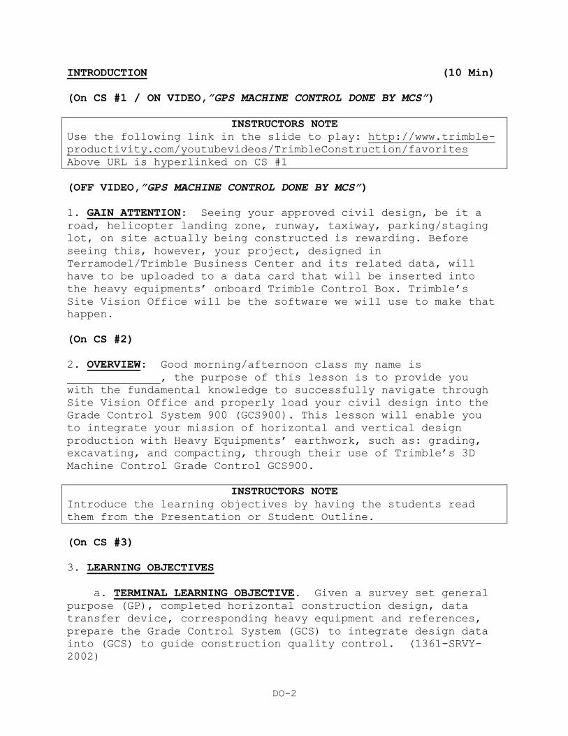
b. 3D Design Simulation. 3D design simulation makes it
simple to visually check the data before you leave the office.
Using the simulation you can drive a virtual machine over the
design, and the SVO screens display the same as it does in the
machine on the job site.
Page 6
DO-6
(On CS #15)
c. Data Transfer/Import/Export. It’s easy to transfer data
from CAD and design software packages using SVO. Most major
CAD/design software such as Terramodel, Paydirt Sitework,
AutoCAD, GEOPAK, and Insite are compatible with SVO and it can
import data from a wide range of formats. You can also export
from SVO to other leading design packages.
(On CS #16)
TRANSITION: Are there any questions at this time?
OPPORTUNITY FOR QUESTIONS:
1. QUESTIONS FROM THE CLASS: Do you have any questions
concerning importing and exporting design data? (Answer
students’ questions.)
2. QUESTIONS TO THE CLASS: If there are no more questions for
me then I have some for you.
a. Who uses SVO?
ANSWER: Earthwork contractors and civil engineers.
b. What other software is SVO compatible with?
ANSWER: Most major CAD/design software.
TRANSITION: Now that we know what SVO is let’s look at how we
are going to use it.
(On CS #17)
2. Create a New Site. (10 Min) Site Vision Office organizes
data into sites.
a. When a new site is created it contains:
(1) Site Maps
(2) Recorded terrain
(3) Avoidance zones
Page 7
DO-7
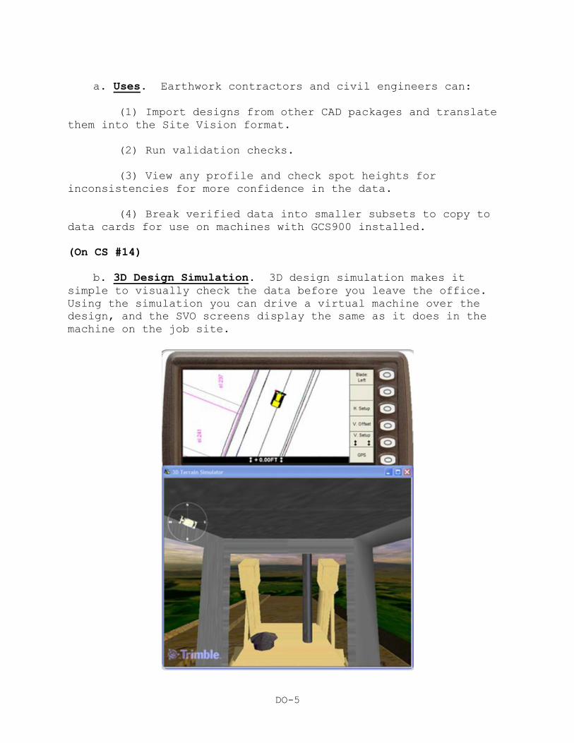
(4) Coordinate systems
(5) Display configurations
(6) Designs
(7) Work orders
(On CS #18)
b. To create a new site you need to:
(1) Start SVO.
(2) Select the new site icon on the tool bar.
(3) Upon creation of a new site and the display options
dialogue will appear.
(On CS #19)
Page 8
DO-8
TRANSITION: Are there any questions at this time?
OPPORTUNITY FOR QUESTIONS:
1. QUESTIONS FROM THE CLASS: Do you have any questions
concerning new site display on the SVO window? (Answer students’
questions.)
2. QUESTIONS TO THE CLASS: If there are no more questions for
me then I have some for you.
a. When a new site is created it what does it contain?
ANSWER: Site Maps, Recorded terrain, Avoidance zones,
Coordinate systems, Display configurations, Designs, Work
orders.
TRANSITION: Now that we know how to create a new site let’s talk
about the display options.
(On CS #20-22)
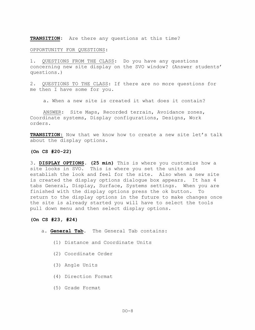
3. DISPLAY OPTIONS. (25 min) This is where you customize how a
site looks in SVO. This is where you set the units and
establish the look and feel for the site. Also when a new site
is created the display options dialogue box appears. It has 4
tabs General, Display, Surface, Systems settings. When you are
finished with the display options press the ok button. To
return to the display options in the future to make changes once
the site is already started you will have to select the tools
pull down menu and then select display options.
(On CS #23, #24)
a. General Tab. The General Tab contains:
(1) Distance and Coordinate Units
(2) Coordinate Order
(3) Angle Units
(4) Direction Format
(5) Grade Format
Page 9
DO-9
(6) Station Format
(7) To change the value within the general tab you will
need to select the value and then select from the list of
options.
(On CS #25)
b. Display Tab. This is where you set the background and
profile line colors for the plan view, cross-section view and
the profile view.
(On CS #26)
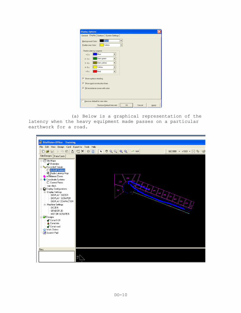
(1). Set the radio latency legend. You will also need to
set the radio latency legend. The radio latency legend is set
for blue for all positions that are within 2 seconds. Data
messages transmitted from the base station to the machine that
arrives within two seconds. Anything that takes more than 2
seconds the GCS900 will not accept and the machine will turn off
the cut and fills.
Page 10
DO-10
(a) Below is a graphical representation of the
latency when the heavy equipment made passes on a particular
earthwork for a road.
Page 11
DO-11
(On CS #27)
(b) Select the options to:
1 Show surface shading for all designs.
2 Show road construction lines.
3 Fill the avoidance zones with color.
(On CS #28)
TRANSITION: Are there any questions at this time?
OPPORTUNITY FOR QUESTIONS:
1. QUESTIONS FROM THE CLASS: Do you have any questions
concerning the Display Options window once a new site is
created? (Answer students’ questions.)
2. QUESTIONS TO THE CLASS: If there are no more questions for
me then I have some for you.
a. How many tabs are there in the display settings?
ANSWER: 4.
b. Name those four tabs?
ANSWER: General, Display, Surface, Systems settings.
TRANSITION: Now that we covered the Display Options we can talk
about the views. What views do you think we will use for a
horizontal project?
INSTRUCTORS NOTE
Explain each different view to the student and what its purpose
is.
(On CS #29)
4. VIEWS. (20min) In SVO you will have three different views to
work with. If you make changes in one view it automatically
updates the other views. This allows you to check the design
data. These views are:
(On CS #30)
Page 12
DO-12
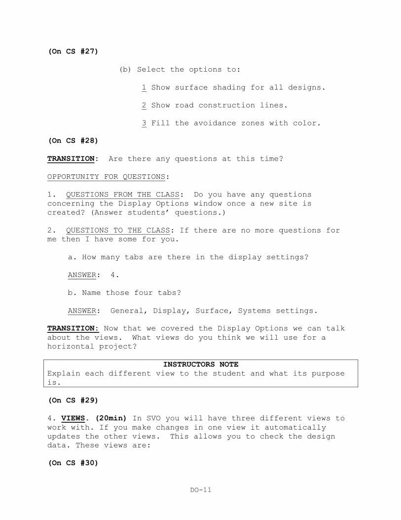
a. Plan View. The “birds-eye” view of your design site. It
graphically displays the surface, recorded terrain, road,
control points, and background files.
(1) You can navigate through your plan view by using the
buttons located on the toolbar.
(2) When you have the cursor arrow on the plan view, the
lower right corner of the window status bar will show the
coordinates (Northing, Easting).
(3) If the cursor arrow is over a design surface, the
elevation will also be displayed with the coordinates.
(4) The coordinates and elevation is confirmed by the
*.dc file used. This is also shown in the status bar.
(On CS #31)
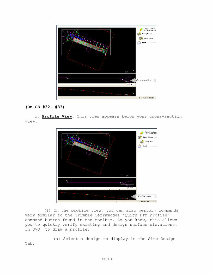
b. Cross-Section View. It graphically displays the cross
section of your design. Below example displays a particular road
cross section at station 0+00.00.
Page 13
DO-13
(On CS #32, #33)
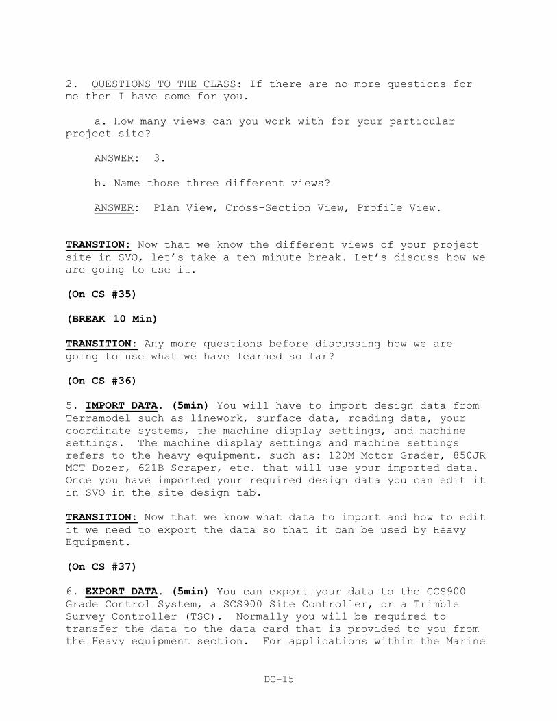
c. Profile View. This view appears below your cross-section
view.
(1) In the profile view, you can also perform commands
very similar to the Trimble Terramodel “Quick DTM profile”
command button found in the toolbar. As you know, this allows
you to quickly verify existing and design surface elevations.
In SVO, to draw a profile:
(a) Select a design to display in the Site Design
Tab.
Page 14
DO-14
(b) Select the profile button in the tool bar.
(c) In the Plan View, click and hold the left mouse
button and drag the mouse across the surface of your selected
design. Then release the left mouse button.
(d) The profile is displayed in the profile view.
(2) The profile you created is a “dynamic” profile.
Meaning, you can position the cursor arrow over the profile line
you created. Click, hold and drag the profile line and the
profile view will dynamically change.
(On CS #34)
TRANSITION: Are there any questions at this time?
OPPORTUNITY FOR QUESTIONS:
1. QUESTIONS FROM THE CLASS: Do you have any questions
concerning SVO View Window panes? (Answer students’ questions.)
Page 15
DO-15
2. QUESTIONS TO THE CLASS: If there are no more questions for
me then I have some for you.
a. How many views can you work with for your particular
project site?
ANSWER: 3.
b. Name those three different views?
ANSWER: Plan View, Cross-Section View, Profile View.
TRANSTION: Now that we know the different views of your project
site in SVO, let’s take a ten minute break. Let’s discuss how we
are going to use it.
(On CS #35)
(BREAK 10 Min)
TRANSITION: Any more questions before discussing how we are
going to use what we have learned so far?
(On CS #36)
5. IMPORT DATA. (5min) You will have to import design data from
Terramodel such as linework, surface data, roading data, your
coordinate systems, the machine display settings, and machine
settings. The machine display settings and machine settings
refers to the heavy equipment, such as: 120M Motor Grader, 850JR
MCT Dozer, 621B Scraper, etc. that will use your imported data.
Once you have imported your required design data you can edit it
in SVO in the site design tab.
TRANSITION: Now that we know what data to import and how to edit
it we need to export the data so that it can be used by Heavy
Equipment.
(On CS #37)
6. EXPORT DATA. (5min) You can export your data to the GCS900
Grade Control System, a SCS900 Site Controller, or a Trimble
Survey Controller (TSC). Normally you will be required to
transfer the data to the data card that is provided to you from
the Heavy equipment section. For applications within the Marine
Page 16
DO-16
Corps we will normally load the info onto the GCS900 or the TSC.
The card actually belongs to the equipment so it is HE’s
responsibility to provide you with the card but you are
responsible for loading the data to it. Once the data is loaded
onto the card you give the card back to HE and they load it into
the equipment.
INTERIM TRANSITION: Now that we have covered how to load the
data onto a data card, are there any questions before we go
through the demonstration.
(On CS #38)
INSTRUCTORS NOTE:
Introduce the following Demonstration.
DEMONSTRATION. (1 Hr) Gather the students’ attention to the
presentation/computer screen for a demonstration of the Trimble
SVO design import and export.
STUDENT ROLE: Observe the Trimble SVO design import and export
procedures.
INSTRUCTOR(s) ROLE: Visually demonstrate, by presentation,
aided by components of the Survey Set GP, illustration and/or
actual samples, to the students, design data import and export
procedure using the Trimble Site Vision Office Software.
1. SAFETY BRIEF: No safety concerns with this class.
2. SUPERVISION & GUIDANCE: Ensure all students can see
material being presented.
DEBRIEF: Now that I have demonstrated road and helicopter landing
zone design data import into the Trimble Site Vision Office
software and export to the data card that the 1345 Heavy
Equipment operator will use for his 3D Machine Control.
INSTRUCTOR INSTRUCTIONS FOR DEMO Present to the students a
completed Terramodel road and pad (HLZ) design, in order to
relate design files to be imported and exported to/from the SVO.
Open SVO office on the Instructor computer and demonstrate the
steps for creating a data card in SVO.
Page 17
DO-17
Site Vision Office Instructions
Importing:
1. Launch SVO
2. Create a new Site: File/New Site
3. Type in a name for the site. Check the path where it is
to be saved to.
4. Check the settings under the General tab.
5. On the display tab, set the Background to white.
6. Deselect Show Surface Shading
7. Deselect Show road construction lines
8. On the Surface tab, deselect Show contours and show
triangles.
9. Nothing to change on the System settings tab.
10. Pick Apply then OK.
11. Use the Import File command to begin importing the
required files.
12. From the Linetype tab select Linework from Terramodel
Project file.
13. Browse to the correct Terramodel file. Pick all layers
you want imported to display linework.
14. Import from the Roads tab the SVD design from
Terramodel Project file.
15. Browse and select the correct Terramodel project file.
Then review and select the correct road.
16. From the Field tab, import a coordinate system from
file. Select the .dc file which contains your correct site
calibration.
17. When prompted to apply the coordinate system to
unlocked designs, pick YES.
Exporting:
Page 18
DO-18
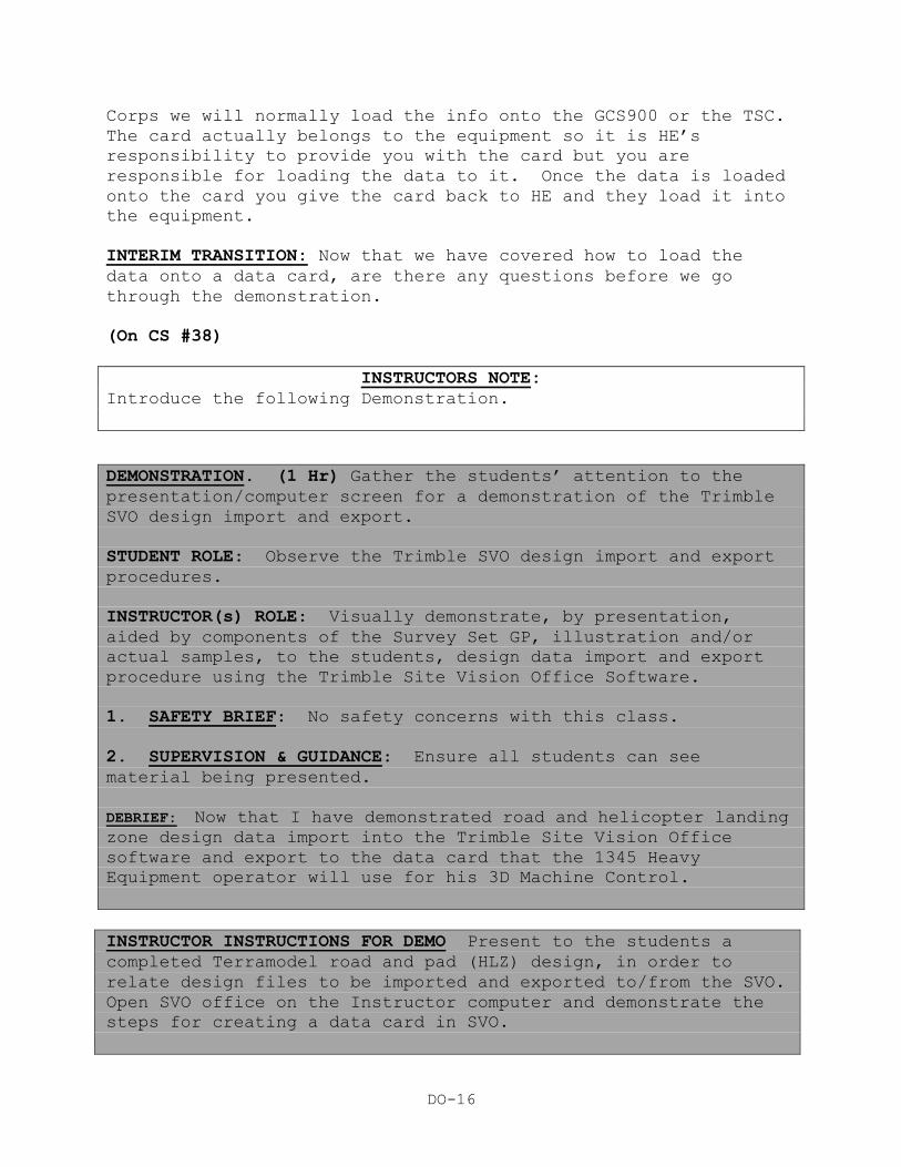
18. Prepare to export the designs to a card.
19. From the top left, make sure the Site designs tab is
selected.
20. Pick the design to export. This activates other
commands and makes them available.
21. From the Export To pulldown menu, select GCS900.
22. Version is 10.0. Export to the CARD. Pick OK.
23. Browse to where you want to create the card and files.
Pick OK.
24. Your card is created. You can now copy the files onto
a CF card.
Verification:
25. Guide students to the site folder created and open up
the “export” folder.
26. The minimum file type extensions that will enable the
Trimble GCS900 to work are: *.svd, *.svl, *.cfg
27. Ensure the student see those files in the export
folder.
(On CS #39)
TRANSITION: You have just seen a demonstration of SVO, are
there any questions at this time? Answer the students’
questions.
OPPORTUNITY FOR QUESTIONS:
1. QUESTIONS FROM THE CLASS: Do you have any questions
concerning importing and exporting design data? (Answer
students’ questions.)
2. QUESTIONS TO THE CLASS: If there are no more questions for
me then I have some for you.
a. What can you export the data to?
Page 19
DO-19
ANSWER: Either a GCS900 Grade Control System, SCS900 Site
Controller or a TSC.
b. Who is responsible for loading the card into the HE?
ANSWER: The Heavy Equipment Operator.
TRANSITION: Now that you have seen the demonstration in SVO
import and export, are there any further questions before we
take a 10 minute break? When we come back, we will discuss
communication establishment and blade calibration.
(On CS #40)
(Break - 10 Min)
TRANSITION: Next we will discuss communication establishment and
blade calibration.
(On CS #41)
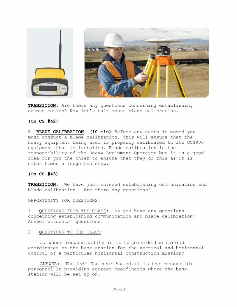
7. ESTABLISH COMMUNICATION. (15 Min) In order for the Grade
Control System 900 (GCS900) to work, you must establish
communication between the base station and the heavy equipment
(grader, dozer, etc.). You will have to ensure that you give
the correct coordinates that you used for you survey and design
data to HE for them to load into their base station. This base
station has an external receiver called the Trimble Site
Positioning System 852 (SPS852). You should be present when he
sets up their base station to ensure that it is done correctly
and that they are on the correct frequency and have the correct
coordinates. The base station that comes with the GCS900
belongs to HE and its setup is the responsibility of the Heavy
Equipment Operator but it is a good idea as a chief to ensure
that they know how to set this up and establish the
communication between their base and the GCS900 installed in the
heavy equipment.
Page 20
DO-20
TRANSITION: Are there any questions concerning establishing
communication? Now let’s talk about blade calibration.
(On CS #42)
8. BLADE CALIBRATION. (10 min) Before any earth is moved you
must conduct a blade calibration. This will ensure that the
heavy equipment being used is properly calibrated to its GCS900
equipment that is installed. Blade calibration is the
responsibility of the Heavy Equipment Operator but it is a good
idea for you the chief to ensure that they do this as it is
often times a forgotten step.
(On CS #43)
TRANSITION: We have just covered establishing communication and
blade calibration. Are there any questions?
OPPORTUNITY FOR QUESTIONS:
1. QUESTIONS FROM THE CLASS: Do you have any questions
concerning establishing communication and blade calibration?
Answer students’ questions.
2. QUESTIONS TO THE CLASS:
a. Whose responsibility is it to provide the correct
coordinates on the base station for the vertical and horizontal
control of a particular horizontal construction mission?
ANSWER: The 1361 Engineer Assistant is the responsible
personnel in providing correct coordinates where the base
station will be set-up on.
Page 21
DO-21
b. Who is responsible in conducting Blade Calibration on a
particular Trimble 3D Machine Control GCS900 enabled heavy
equipment?
ANSWER: The 1345 Heavy Equipment Operator is responsible in
conducting blade calibration on a particular heavy equipment he
will be operating.
TRANSITION: Are there any more questions before going into the
practical applications.
(On CS #44)
INSTRUCTORS NOTE
Introduce the following tutorial/Practical Application.
STUDENT TUTORIAL/PRACTICAL APPLICATION (2 HOURS)
At this time launch the Site Vision Office tutorial from the
Trimble Ltd. website, Trimble Knowledge Network Learning Center
(http://www.trimblelms.com/tr_open_main_main.asp) and lead the
entire class through the tutorial. Allow (2 hours) for this.
INTERIM TRANSITION: Are there any questions from the tutorial
you have just completed? Answer the students’ questions. At this
time, let’s take a ten minute break.
(On CS #45)
(Break - 10 Min)
(On CS #46)
INSTRUCTORS NOTE
Introduce the following practical application.
PRACTICAL APPLICATION: (10.5 Hrs)
Have the students take the GPS gear outside and conduct control
and topographic surveys. Once the surveys are completed they
will load their data into Terramodel and design a horizontal
construction project. Have the students conduct Trimble Site
Vision Office (SVO) software in the classroom importing and
exporting horizontal construction project files produced in the
Page 22
DO-22
Trimble Terramodel software. In the field, with the Trimble Site
Positioning System Modular Receiver (SPS852), set-up and input
coordinates on a particular project control point. In the field,
locate a suitable spot for H.E. blade calibration area.
PRACTICE: With completed road and pad designs, conduct import
and export procedures with the Trimble SVO software. With
correct project control point coordinates, input data into the
Trimble SPS852. Establish blade calibration area for the 1345
Heavy Equipment Operator.
PROVIDE-HELP: Ensure students have all training aids, such as:
Laptops with Trimble Terramodel, Trimble Site Vision Software,
and references. Ensure coordination with the EEIC Marine Unique
Section has been completed for the temporary loan of the Trimble
SPS852. Walk around the classroom and aid the students in their
design data import and export. Remind them that these practical
exercises will be part of their examination. Answer all
questions the students may have.
SAFETY BRIEF: No safety concerns with this class.
SUPERVISION & GUIDANCE: Be sure to follow the step by step
directions covered in your student outline, from the tutorial,
and from the demonstration presented earlier.
DEBRIEF: Now that we have conducted SVO import and upload
procedures, verified that pertinent files are in the data card,
ensured correct coordinates are inputted in the SPS852 and
created an area for heavy equipment blade calibration, you as a
1361 Engineer Assistant Chief will be confident that your
horizontal design product will integrate with the Heavy
Equipment Trimble 3D Machine Control.
TRANSITION: You have just spent the last 13 hours conducting
practical applications.
(On CS #47)
OPPORTUNITY FOR QUESTIONS:
1. QUESTIONS FROM THE CLASS: Do you have any questions
concerning the practical exercises you have just completed?
Answer students’ questions.
2. QUESTIONS TO THE CLASS:
Page 23
DO-23
a. How many file types are needed for heavy equipment 3D
Machine Control to work?
ANSWER: Three
b. What are the minimum file type extensions needed for
heavy equipment 3D Machine Control to work?
ANSWER: *.svl, *.svd and *.cfg file type extensions.
(On CS #48)
Summary: (5 Min)
In this period of instruction we have covered Site Vision
Office, who uses it, what they use it for, how to create a new
site, the display options, views, site design tab, how to import
and export data how to establish communication between the base
and rovers and who conducts a blade calibration. Please turn in
your IRFs and take a break.
(Break - 10 Min)
REFERENCES:
Earthmoving Operations MCRP 3-17.7I
Trimble 5900-06-ENG GCS900 Operators TM 09130B-OR/1 &
TM 11907B-OR
Manual
Grade Control System Users Manual OEM, GCS Users Manual
TM 11907B-OR
Site Vision Office Getting Started Guide Trimble# 43422-10-
ENG Ver 7.40
Trimble Terra Model User Guide OEM, Trimble Terra
Model