Page 1 of 12 LESSONS LEARNED IN THE LAUNCHING OF STEEL GIRDER BRIDGES T. Andres Sanchez, Ph.D. Michael LaViolette, P.E. BIOGRAPHY T. Andres Sanchez is the CEO at ADSTREN in Quito, Ecuador. He received a Ph.D. from Georgia Institute of Technology in Civil Engineering. He has worked in the design of numerous bridges in the US, Ecuador, and Colombia. His field of expertise is the design of steel structures. Mike LaViolette is Professional Associate and National Bridge Practice Leader with HDR. He has over 26 years of experience in complex bridge design and construction engineering services for US and international projects. Mike was the lead bridge designer for the I-94 2 nd Avenue Bridge and previously, Mike served as the Deputy Design Manager overseeing all structural design for the Tappan Zee Bridge and later as the Design Coordinator for the PennDOT Rapid Bridge Replacement Program. Mike earned his BS (Civil Engineering) and MS (Structural Engineering) degrees from Iowa State University. SUMMARY Launching of steel girder bridges is a construction method that is implemented when the terrain conditions allow the assembling of the structure behind one of the abutments. This methodology may be safer, faster, and more cost effective than other traditional erection procedures since most of the operations are conducted on firm soil. This paper presents the details of the launching operations of two bridges recently constructed by incremental launching. The first case study, the Los-Pajaros Bridge, is a three-span continuous I-girder structure with a total length of 639’-6” that was originally designed as three independent simple spans and was converted to continuous spans in a value engineering improvement to facilitate launching. The second case study is the Villorita Bridge, a two-span continuous tub- girder structure with span lengths of 171’-4” and 304’- 3”. The paper focuses on three aspects of bridges erected with launching methods: the implementation of the incremental launching method and its benefits, the design calculations and the limit states that apply to girders in cantilever, and the expected versus real structural behavior in terms of girder stresses and cantilever displacements.
Transcript
Page 1 of 12
LESSONS
LEARNED IN THE
LAUNCHING OF
STEEL GIRDER
BRIDGES
T. Andres Sanchez, Ph.D.
Michael LaViolette, P.E.
BIOGRAPHY
T. Andres Sanchez is the CEO
at ADSTREN in Quito,
Ecuador. He received a Ph.D.
from Georgia Institute of
Technology in Civil
Engineering. He has worked in
the design of numerous
bridges in the US, Ecuador,
and Colombia. His field of
expertise is the design of steel
structures.
Mike LaViolette is
Professional Associate and
National Bridge Practice
Leader with HDR. He has
over 26 years of experience in
complex bridge design and
construction engineering
services for US and
international projects. Mike
was the lead bridge designer
for the I-94 2nd
Avenue Bridge
and previously, Mike served as
the Deputy Design Manager
overseeing all structural design
for the Tappan Zee Bridge and
later as the Design Coordinator
for the PennDOT Rapid
Bridge Replacement Program.
Mike earned his BS (Civil
Engineering) and MS
(Structural Engineering)
degrees from Iowa State
University.
SUMMARY
Launching of steel girder
bridges is a construction
method that is implemented
when the terrain conditions
allow the assembling of the
structure behind one of the
abutments. This methodology
may be safer, faster, and more
cost effective than other
traditional erection procedures
since most of the operations
are conducted on firm soil.
This paper presents the details
of the launching operations of
two bridges recently
constructed by incremental
launching. The first case study,
the Los-Pajaros Bridge, is a
three-span continuous I-girder
structure with a total length of
639’-6” that was originally
designed as three independent
simple spans and was
converted to continuous spans
in a value engineering
improvement to facilitate
launching. The second case
study is the Villorita Bridge, a
two-span continuous tub-
girder structure with span
lengths of 171’-4” and 304’-
3”. The paper focuses on three
aspects of bridges erected with
launching methods: the
implementation of the
incremental launching method
and its benefits, the design
calculations and the limit
states that apply to girders in
cantilever, and the expected
versus real structural behavior
in terms of girder stresses and
cantilever displacements.
Page 2 of 12
LESSONS LEARNED IN THE LAUNCHING OF STEEL
GIRDER BRIDGES
ABSTRACT
Launching of steel girder bridges is a construction method that is implemented when the terrain conditions
allow the assembling of the structure behind one of the abutments. This methodology may be safer, faster, and
more cost effective than other traditional erection procedures since most of the operations are conducted on
firm soil. This paper presents the details of the launching operations of two bridges recently constructed by
incremental launching. The first case study, the Los-Pajaros Bridge, is a three-span continuous I-girder
structure with a total length of 639’-6” that was originally designed as three independent simple spans and
was converted to continuous spans in a value engineering improvement to facilitate launching. The second
case study is the Villorita Bridge, a two-span continuous tub-girder structure with span lengths of 171’-4” and
304’-3”. The paper focuses on three aspects of bridges erected with launching methods: the implementation of
the incremental launching method and its benefits, the design calculations and the limit states that apply to
girders in cantilever, and the expected versus real structural behavior in terms of girder stresses and cantilever
displacements.
INTRODUCTION
The incremental launching method (ILM) is a
technique in which a bridge structure is assembled
behind one of the end supports and then it is
moved longitudinally to cross over an obstacle,
passing over the intermediate piers until it reaches
the far abutment. When proper considerations are
taken, the steel erection with ILM can be safer,
faster, and more cost-effective than other methods.
The assembly of the structure on a firm surface is
an advantage that reduces the possibilities of
accidents and normally, requires less crane
capacities than other erection schemes. Similarly,
the construction time is usually reduced since the
launching operation is almost continuous, from the
moment that the structure starts moving
longitudinally, until it reaches the end support.
This paper presents the lessons learned during the
construction of two steel girder bridges erected
using this method: the Los-Pajaros Bridge and the
Villorita bridge, both located in Quito, Ecuador.
These bridges were constructed as part of the
Simon Bolivar Ave. extension, which improves
the connection between the north part of the city
and the neighboring towns of Pusuqui and San
Antonio. Figure 1 shows an aerial view of the
Simon Bolivar Ave. extension and bridge
locations.
Case Study 1: Los-Pajaros Bridge
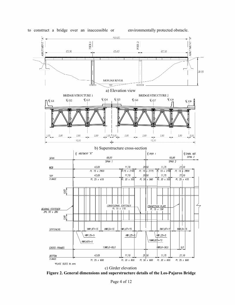
The Los-Pajaros Bridge is a 195.0m (640ft) long
structure with three equal spans that
accommodates five lanes: four for motorized
traffic and one for bicycles. Figure 2 shows an
elevation view, the bridge cross-section, and the
geometry of a typical girder. To facilitate the
construction, the bridge is divided in two
structures of four and five girders named
Structures 1 and 2, respectively. The composite
superstructure consists of I-girders connected with
inverted “V” type cross-frames, topped with a
20cm (8in.) thick reinforced concrete deck. The
superstructure is made of ASTM A588 Gr.50 steel
and is supported by typical reinforced concrete
abutments at the ends and two equal intermediate
piers with cell-type sections of an approximate
35m (115ft) height. The exterior supports are
abutments designed to resist the vertical,
transverse, and longitudinal forces that are
transferred from the composite superstructure.
During the design phase, two options were
considered to erect the superstructure. In the first
one, provisional erection towers would be placed
at approximately the third points of each span.
Then, cranes located at the road level and on the
sloped terrain would manipulate the girder
segments to support them on the provisional
towers and the substructure. The last step would
be to make the field connections and remove the
towers.
Page 3 of 12
Figure 1. Project Location
This method, however, has two major
disadvantages: Firstly, large crane capacities are
needed to manipulate heavy girder segments at
more than 30m (98ft) of height. Secondly, this
method requires the construction of provisional
structures that would not be used after the bridge
is erected.
The other option was to use the ILM by
assembling the entire steel structures behind
Abutment “B”, where there is enough space to
maneuver and conduct all girder assembly
operations. This method proved to be safer and
more cost-effective than the previous. Some of the
benefits of the ILM are that all operations are
conducted on firm soil, there is no need to locate
any construction items in the sloped terrain, and it
is significantly faster than the other method. For
these reasons, the ILM was selected for the
construction of this structure, and specific design
features were implemented in the steel structure
geometry to facilitate the launching process.
LaViolette et al (2007) present a thorough
discussion of aspects that need to be considered
for successfully implementing ILM in steel girder
bridges. These recommendations were considered
in the design of the Los-Pajaros Bridge.
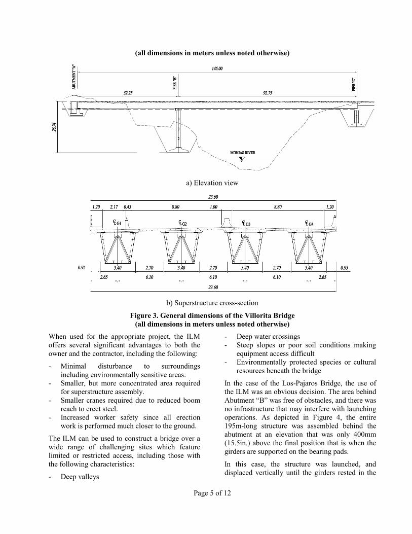
Case Study 2: Villorita Bridge
The Villorita Bridge is a steel tub-girder structure
with two continuous spans of 52.25m (171.4ft)
and 92.75m (304.2m) of length. Similarly, to Case
Study 1, this bridge has a total width of 23.60m
(77.4ft) with four traffic lanes and one lane for
bicycles. Figure 3 shows the elevation view and a
typical cross-section of the bridge.
The structural system selected for the construction
of this bridge is different to the steel I-girder
configuration used in Los-Pajaros Bridge. The
main reason for this change is the torsional
stiffness of the tub-girders, which increases the
lateral-torsional buckling strength of the system
during launching, as it is discussed in further detail
in later sections.
IMPLEMENTATION OF ILM IN
THE CONSTRUCTION OF THE
CASE STUDIES
As discussed in this section, ILM was the most
effective construction method for both of the case
studies; however, the launching method will likely
never become the most economical procedure for
constructing a particular bridge. Launching a
bridge requires a considerable amount of analysis
of the unusual loading and support conditions,
design expertise to accommodate these conditions
and specialized construction equipment including
rollers, jacks and launching nose. However,
launching may often be the most reasonable way
Page 4 of 12
to construct a bridge over an inaccessible or environmentally protected obstacle.
a) Elevation view
b) Superstructure cross-section
c) Girder elevation
Figure 2. General dimensions and superstructure details of the Los-Pajaros Bridge
Page 5 of 12
(all dimensions in meters unless noted otherwise)
a) Elevation view
b) Superstructure cross-section
Figure 3. General dimensions of the Villorita Bridge
(all dimensions in meters unless noted otherwise)
When used for the appropriate project, the ILM
offers several significant advantages to both the
owner and the contractor, including the following:
- Minimal disturbance to surroundings
including environmentally sensitive areas.
- Smaller, but more concentrated area required
for superstructure assembly.
- Smaller cranes required due to reduced boom
reach to erect steel.
- Increased worker safety since all erection
work is performed much closer to the ground.
The ILM can be used to construct a bridge over a
wide range of challenging sites which feature
limited or restricted access, including those with
the following characteristics:
- Deep valleys
- Deep water crossings
- Steep slopes or poor soil conditions making
equipment access difficult
- Environmentally protected species or cultural
resources beneath the bridge
In the case of the Los-Pajaros Bridge, the use of
the ILM was an obvious decision. The area behind
Abutment “B” was free of obstacles, and there was
no infrastructure that may interfere with launching
operations. As depicted in Figure 4, the entire
195m-long structure was assembled behind the
abutment at an elevation that was only 400mm
(15.5in.) above the final position that is when the
girders are supported on the bearing pads.
In this case, the structure was launched, and
displaced vertically until the girders rested in the
Page 6 of 12
bearings with minor effort since the structure was
lowered with jacks of a short stroke.
Figure 4. Structure assembly of the Los-Pajaros
Bridge
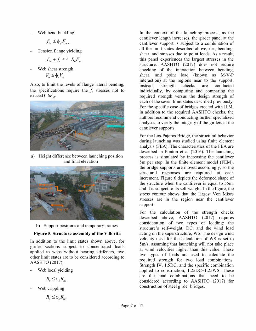
In the Villorita Bridge, the surrounding conditions
complicated the launching process of the structure.
As shown in Figure 5a, the structure had to be
assembled at an elevation approximately 4m (13ft)
above the bearing level. The structure could not be
assembled at a lower elevation due to the presence
of a sewer system and ducts for electricity under
the structure. For that reason, temporary steel
frames had to be erected at four locations to
conduct the launching process (Figure 5b). In
addition, the girders were launched in pairs, given
the site constraints. As shown in the figure, at
Support B’, there was not enough space to
construct the foundation for the four girders;
therefore, the first two girders were launched,
lowered and mounted on skids, moved
transversely, and lowered again to their final
position on the bearings.
Lowering the first pair of girders supposed a major
operation during the construction process. Once
the longitudinal movement of the girders was
finished, the structure had to be jacked up to
remove the temporary frames and lowered 4m
(13ft) until it rested in the sliding skids. For this
operation, the entire structure was jacked at three
points, Abutment “A”, Pier “B”, and Pier “C”.
Strict control of the forces in the strand jacks was
taken as the girders moved down. Also,
anemometers were installed to measure wind
speeds. According to the structural analyses,
operations had to be halted at wind speeds above
5m/s, that is the speed at which the pendulum
effect exerts significant lateral forces in the
support structures.
Due to the different maneuvers involved in the
construction of the Villorita Bridge (i.e.,
launching, lowering to skids, sliding, and lowering
to bearings), in an early design stage, it was
decided to construct this structure with steel tub-
girders. The torsional stiffness of the quasi-closed
sections increased the overall rigidity of the girder
system, which helped control the geometry of the
it during the entire process.
In general, the ILM was used for the construction
of these bridges because of its advantages over
other traditional methods. By comparing the
construction of the Los-Pajaros Bridge and the
Villorita Bridge, it is clear that the second was
considerably more difficult than the first, due to
the site constraints, being the lowering operation,
the most challenging step in the construction
sequence. Whenever it is possible, as in the case of
the Los-Pajaros Bridge, it is recommended to
assembly the bridge structure at an elevation that
is close to the final bottom flange elevation, so the
equipment needed to bring down the girders to the
bearing pads is limited to short-stroke jacks. This
practice reduces the time, the effort, and the risk
level implicit in the structure’s lowering since this
operation may take as many resources as the
launching itself.
AASHTO DESIGN CHECKS
DURING CONSTRUCTION
The AASHTO Bridge Design Specifications
(AASHTO 2017) requires the designer to conduct
five different strength checks during construction
for steel I-girders subject to flexure and shear.
These are:
- Compression flange yielding
bu f h ycf f R F
- Compression flange stability
/ 3bu f h ncf f R F
Page 7 of 12
- Web bend-buckling
bu f crwf F
- Tension flange yielding
bu f h ytf f R F
- Web shear strength
u v crV V
Also, to limit the levels of flange lateral bending,
the specifications require the f stresses not to
exceed 0.6Fyf.
a) Height difference between launching position
and final elevation
b) Support positions and temporary frames
Figure 5. Structure assembly of the Villorita
In addition to the limit states shown above, for
girder sections subject to concentrated loads
applied to webs without bearing stiffeners, two
other limit states are to be considered according to
AASHTO (2017):
- Web local yielding
u b nyR R
- Web crippling
u b ncR R
In the context of the launching process, as the
cantilever length increases, the girder panel at the
cantilever support is subject to a combination of
all the limit states described above, i.e., bending,
shear, and stresses due to point loads. As a result,
this panel experiences the largest stresses in the
structure. AASHTO (2017) does not require
checking of the interaction between bending,
shear, and point load (known as M-V-P
interaction) at the regions near to the support;
instead, strength checks are conducted
individually, by computing and comparing the
required strength versus the design strength of
each of the seven limit states described previously.
For the specific case of bridges erected with ILM,
in addition to the required AASHTO checks, the
authors recommend conducting further specialized
analyses to verify the integrity of the girders at the
cantilever supports.
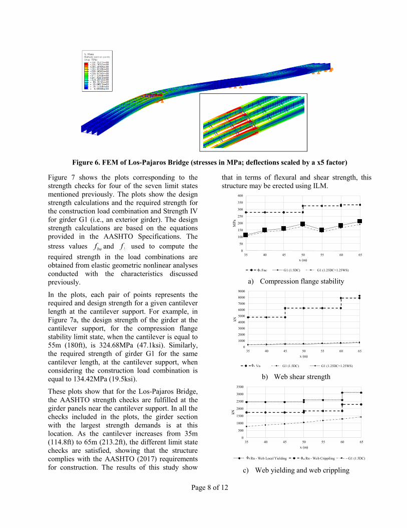
For the Los-Pajaros Bridge, the structural behavior
during launching was studied using finite element
analysis (FEA). The characteristics of the FEA are
described in Ponton et al (2016). The launching
process is simulated by increasing the cantilever
5m per step. In the finite element model (FEM),
the bridge supports are moved accordingly, so the
structural responses are captured at each
increment. Figure 6 depicts the deformed shape of
the structure when the cantilever is equal to 55m,
and it is subject to its self-weight. In the figure, the
stress contour shows that the largest Von Mises
stresses are in the region near the cantilever
support.
For the calculation of the strength checks
described above, AASHTO (2017) requires
consideration of two types of loading: the
structure’s self-weight, DC, and the wind load
acting on the superstructure, WS. The design wind
velocity used for the calculation of WS is set to
5m/s, assuming that launching will not take place
at wind velocities higher than this value. These
two types of loads are used to calculate the
required strength for two load combinations:
Strength IV, 1.5DC, and the specific combination
applied to construction, 1.25DC+1.25WS. These
are the load combinations that need to be
considered according to AASHTO (2017) for
construction of steel girder bridges.
Page 8 of 12
Figure 6. FEM of Los-Pajaros Bridge (stresses in MPa; deflections scaled by a x5 factor)
Figure 7 shows the plots corresponding to the
strength checks for four of the seven limit states
mentioned previously. The plots show the design
strength calculations and the required strength for
the construction load combination and Strength IV
for girder G1 (i.e., an exterior girder). The design
strength calculations are based on the equations
provided in the AASHTO Specifications. The
stress values buf and f used to compute the
required strength in the load combinations are
obtained from elastic geometric nonlinear analyses
conducted with the characteristics discussed
previously.
In the plots, each pair of points represents the
required and design strength for a given cantilever
length at the cantilever support. For example, in
Figure 7a, the design strength of the girder at the
cantilever support, for the compression flange
stability limit state, when the cantilever is equal to
55m (180ft), is 324.68MPa (47.1ksi). Similarly,
the required strength of girder G1 for the same
cantilever length, at the cantilever support, when
considering the construction load combination is
equal to 134.42MPa (19.5ksi).
These plots show that for the Los-Pajaros Bridge,
the AASHTO strength checks are fulfilled at the
girder panels near the cantilever support. In all the
checks included in the plots, the girder section
with the largest strength demands is at this
location. As the cantilever increases from 35m
(114.8ft) to 65m (213.2ft), the different limit state
checks are satisfied, showing that the structure
complies with the AASHTO (2017) requirements
for construction. The results of this study show
that in terms of flexural and shear strength, this
structure may be erected using ILM.
a) Compression flange stability
b) Web shear strength
c) Web yielding and web crippling
0
50
100
150
200
250
300
350
400
35 40 45 50 55 60 65
MP
a
x (m)
Fnc G1 (1.5DC) G1 (1.25DC+1.25WS)φf
0
1000
2000
3000
4000
5000
6000
7000
8000
9000
35 40 45 50 55 60 65
kN
x (m)
Vn G1 (1.5DC) G1 (1.25DC+1.25WS)φv
0
500
1000
1500
2000
2500
3000
3500
35 40 45 50 55 60 65
kN
x (m)
Rn - Web Local Yielding Rn - Web Crippiling G1 (1.5DC)φwφb
Page 9 of 12
Figure 7. AASHTO construction checks, G1
The strength calculations show that the demands
are relatively low versus the structure’s capacity.
However, the AASHTO design checks should be
complemented with a more detailed study of the
structure, where the M-V-P interaction is captured
to verify its integrity during launching. Analyzing
the structure with a 3D FEA, as the one shown for
the Los-Pajaros bridge, is essential to properly
capture the bridge behavior in the construction
process.
PREDICTED VERSUS REAL
BEHAVIOR DURING
LAUNCHING
Two structural responses that are commonly
monitored during the launching process are the
vertical deflections and the major-axis bending
stresses in the girder flanges. The first response is
measured with standard surveying equipment,
while the stresses are measured with strain gauges.
Since the deformations in the girders are elastic,
the measured strains are multiplied by the steel
elastic modulus to transform them into stresses.
Sanchez et al (2018) presents the details of the
instrumentation used in the launching of the Los-
Pajaros Bridge to measure strain and stresses.
Figure 8 presents the plots with the response
predictions using FEA and the measurement taken
during the launching process. The launching
length, which ranges between 0m (0ft) and 195m
(639.6ft), is shown in the horizontal axis. The
vertical axis in Figure 8a shows the vertical
displacements at the girder tip. As depicted in this
figure, during the first stages of launching, the
measured girder deflections are larger than those
predicted by the FEA. For example, when the
launching length is equal to 40m (131.2ft), the
measured and predicted deflections are 577mm
(22.7in.) and 434mm (17.1in.), respectively. The
differences between the expected and real
responses are due to the continuity effects given
by the launching skids, located behind the
abutment. The jacks in the skids can be moved up
or down to control and distribute the forces in
these supports, as the structure is moved forward.
When the pistons in the skids that are closer to the
cantilever support are moved up, the launching
nose and the girders tend to deflect more. In
general, steel girders are flexible, and changes in
support conditions can affect the vertical
displacement at the girder tip. As launching
progresses, and the continuity effects due to the
skids are less influential, the expected and
measured responses converge. Figure 8a shows
that between x=130m (426.4ft) and x=170m
(557.6ft) both responses are essentially the same.
In this part of the launching, the structure moves
from Pier 1 towards Abutment “A” (see Figure 2)
that is the final part of the launching process. The
reason why both responses are similar at this stage
is because the analytical prediction properly
represents the support conditions in the real
structure.
a) Vertical displacement at the end of the girder
b) Top flange major-axis bending stress
c) Bottom flange major-axis bending stress
Figure 8. Predicted versus measured responses
during launching
-650
-600
-550
-500
-450
-400
-350
-300
-250
-200
-150
-100
-50
0
50
100
0 20 40 60 80 100 120 140 160 180 200
Def
lect
ion [
mm
]
Launching Length (m)
Deflexión Real Vs. Deflexión por FEA (LARSA4D)
Measured Deflection Expected Deflection
Day 1 Day 2 Day 3 Day 4 Day 5
Oct 23 9:55 AM
Oct 24 10:42 AM
Oct 25 9:05 AM
Oct 25 12:28 PM
Oct 26 9:14 AM
Page 10 of 12
At the launching length of 170m (557.6ft), for
example, the structure is supported at Abutment
“B”, Pier 2, Pier1, and at a few skid pair. At this
point, however, the effect of the skids in the
cantilever displacement is negligible.
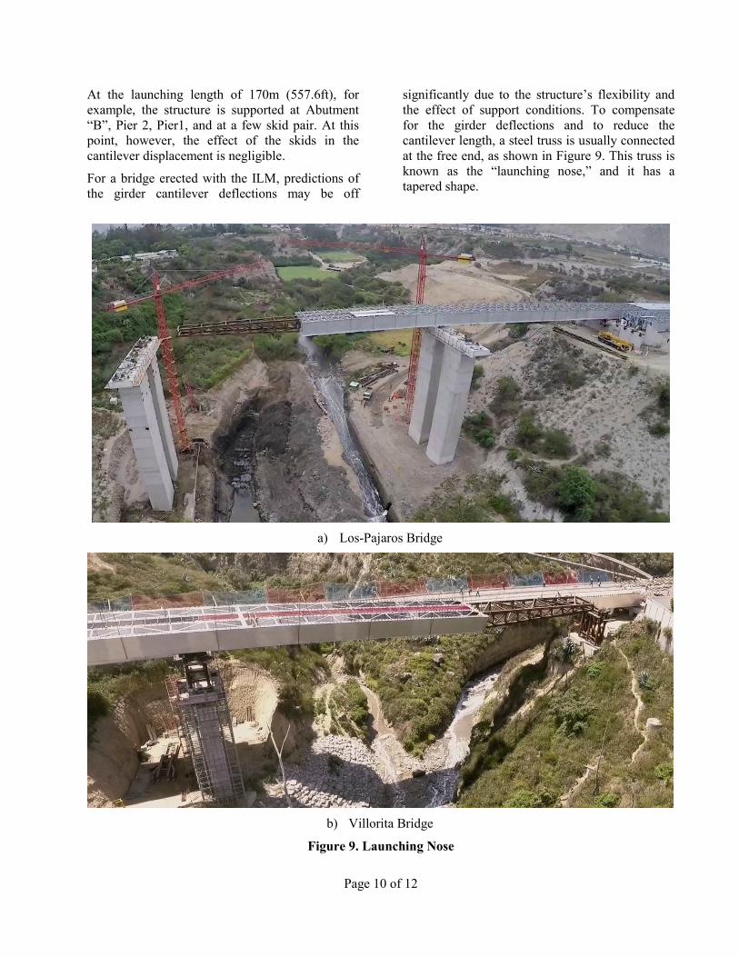
For a bridge erected with the ILM, predictions of
the girder cantilever deflections may be off
significantly due to the structure’s flexibility and
the effect of support conditions. To compensate
for the girder deflections and to reduce the
cantilever length, a steel truss is usually connected
at the free end, as shown in Figure 9. This truss is
known as the “launching nose,” and it has a
tapered shape.
a) Los-Pajaros Bridge
b) Villorita Bridge
Figure 9. Launching Nose
Page 11 of 12
At the connection with the girders, the nose and
girder heights are the same. At the free end, the
truss height is shorter, so it accommodates the
cantilever deflections and facilitates the landing on
the rollers. The theoretical height difference
between both ends would be equal to the girder
deflection at the maximum cantilever length (i.e.,
the longest span minus the nose length). However,
as previously mentioned, due to continuity effects,
the girders tend to deflect more than the analytical
predictions. Hence, it is recommended to design
the taper of the launching nose considering at least
a 30% deflection increase, so there is certainty that
the nose will land on the rollers without
difficulties.
The other response of interest that is measured
during the construction process is the flange
stresses due to major-axis bending. Figure 8b and
8c show the stress measurements and predictions
at the top and bottom flanges, respectively, at a
girder cross-section located at 40m (131.2ft) from
the cantilever free end. As shown in the figure, the
analytical model is an accurate representation of
the real behavior. This result is expected since the
cantilever is an isostatic structure, so the support
reactions may be calculated with accuracy even
with hand calculations. Contrary to the girder
deflections, the stress responses are not sensitive
to the support conditions.
These figures show that during the entire
launching process, the girders are subject to
relatively low stress levels. Both tension and
compression stresses are bound between 200MPa
(28.9ksi) and 170MPa (24.6ksi), which represent
less than 60% of the yielding point of the Gr.50
steel used in the construction of this bridge. This
observation is in agreement with the calculations
of the AASHTO strength checks that show that
during the entire launching process, the required
strengths are well below the design strengths for
the different limit states.
CONCLUSIONS
This paper discusses the implementation of the
ILM for the construction of the Los-Pajaros
Bridge and the Villorita Bridge. The launching
operations were successful, and there were not
significant complications during this process. To
implement the ILM, it is necessary to conduct
specialized studies that confirm that the structure
is stable when the girders are in cantilever.
Strength checks according to the AASHTO
Specifications must be considered to verify that as
a result of the high demands experienced during
launching, the bridge will not be subject to stress
levels that may compromise its performance once
it is in operation. Additionally, it is suggested to
conduct further studies to verify the strength of the
girder at the cantilever support due to the M-V-P
interaction since this check is not explicitly
required by the AASHTO Specifications.
These bridges are the first to be erected in Ecuador
using this methodology. The coordination between
all the parts involved in the project was a key
factor to successfully complete the erection of the
structures. The ILM is not necessarily the most
economical procedure to construct a bridge;
however, given that almost all operations are
conducted on firm soil, it is a methodology that
reduces the risk of accidents, facilitates the
inspection of the structural components, and
considerably reduces the construction times.
REFERENCES
AASHTO (American Association of State
Highway and Transportation Officials) (2017).
“LRFD Bridge Design Specifications” 8th Edition,
Washington, DC.
LaViolette, M., Wipf, T., Lee, Y., Bigelow, J., and