Copyright © 2015 ARM Limited or its affiliates. All rights reserved. ARM is a registered trademark of ARM, Limited in the EU and/or elsewhere. All rights reserved.
All other trademarks are the property of their respective owners and are acknowledged.
Page 1 of 28
Lessons from the field – IP/SoC integration
techniques that work
David Murray, IP Tooling Architect
IP Tooling, Systems and Software,
ARM – [email protected]
Simon Rance, Senior Product Manager,
IP Tooling, Systems and Software,
ARM – [email protected]
ABSTRACT
IP integration is increasingly seen as a key challenge in SoC development. Many factors combine
to compound the problem of IP integration. Increased system complexity, IP reuse, IP
configurability and tightly-bound schedules have all combined to break traditional flows and
methodologies. The EDA industry has identified IP integration as one of the next big challenges
and has responded by envisioning a plug-and-play type of standardized IP that can be treated
like Lego blocks when it comes to IP integration. A solution for this Lego concept that has been
emerging for several years is the use of IP metadata to describe, standardize and formalize IP
interfaces to enable more efficient IP integration flows. The primary solution put forward by the
industry is IP-XACT (IEEE-1685), a standard that includes a schema definition for IP metadata.
While the usage of IP-XACT has been growing, the lack of a standard integration methodology
has severely limited vendors’ ability to provide the fully interoperable IP metadata necessary to
enable rapid and reusable IP integration flows. This paper presents a standards-based IP
integration methodology that aims to solve these challenges. The solution presented combines
the standardization of IP interfaces with a corresponding rules-based integration methodology
that leverages these interfaces to provide rapid and high-quality IP integration. The capabilities,
benefits and limitations of using IP-XACT to standardize configurable IP are explored, as well as
how the industry is really using the IP-XACT standard. This includes an overview of the work
Copyright © 2015 ARM Limited or its affiliates. All rights reserved. ARM is a registered trademark of ARM, Limited in the EU and/or elsewhere. All rights reserved.
All other trademarks are the property of their respective owners and are acknowledged.
Page 2 of 28
being done by the Accellera Systems Initiative to help with IP interoperability using
standardized bus definitions. This paper also includes a case study on the integration of a
complex ARM IP-based system, detailing the rules-based approach taken to integrating the
system. Metrics are presented that show an 8-fold schedule improvement on a first-time
project and a potential 20-fold improvement over traditional methods by adopting the rules-
based approach. This methodology also results in benefits such as higher quality connectivity
and highly reusable design integration intent. This paper concludes with a list of
recommendations for implementing a highly efficient IP integration flow.
Keywords—IP Reuse; IP Integration; IP-XACT; Rules-based integration
INTRODUCTION
As IP reuse becomes more mainstream in SoC realization, IP integration is increasingly seen as a
key challenge and a growing contributor to the overall cost of SoC development [1]. There are
many factors that combine to compound the problem of IP integration.
The increase in SoC design complexity means more IP blocks and sub-systems to integrate
together.
The constant drive to reduce SoC development schedules and costs, without impacting on
quality, has led to pressure to reuse internal and third-party IP and to integrate these IP as
quickly and efficiently as possible.
IPs are becoming more complex and configurable and can have thousands of ports and
hundreds of different configurations.
Design teams are not being scaled to the same level as the problem, and so bigger problems
have to be managed by fewer people.
Copyright © 2015 ARM Limited or its affiliates. All rights reserved. ARM is a registered trademark of ARM, Limited in the EU and/or elsewhere. All rights reserved.
All other trademarks are the property of their respective owners and are acknowledged.
Page 3 of 28
The poor adoption of standards and methodologies for IP integration is making efficient and
reusable integration more difficult.
The result is a poor quality IP integration process that has been identified as one of the main
chip design challenges [2][3][4].
IP integration can touch on many different areas including RTL assembly and connectivity,
HW/SW integration and other perspectives such as clock, reset, power etc. This paper will focus
on the efficient and rapid creation of the RTL structural netlist of a system from a set of RTL IP.
Whilst many of the solutions presented in this paper are also applicable to other integration
perspectives, the scope will be limited to RTL IP integration.
INTEGRATION EVOLUTION
Traditionally the integration of IP components focused on the instantiation of blocks/modules
and their interconnection via schematic editors. In terms of the overall chip development, this
integration activity was seen as one of the final design tasks, close to the end of the
development cycle. Blocks with tens of ports could be connected graphically by simply drawing
wires between the ports. There may have been several hundreds of connections to make and
the task could be completed in a matter of days.
With the advent of RTL, the integration task was implemented using both schematic
editing and direct editing of RTL code. However, as designs became more complex, neither
schematic nor RTL-based approaches could scale appropriately. Specifying and reviewing
connectivity in RTL is a cumbersome process as connections are fragmented throughout the RTL
code.
Copyright © 2015 ARM Limited or its affiliates. All rights reserved. ARM is a registered trademark of ARM, Limited in the EU and/or elsewhere. All rights reserved.
All other trademarks are the property of their respective owners and are acknowledged.
Page 4 of 28
To counter this, many companies have evolved internal solutions involving the use of
connectivity specifications and/or scripts. Many such solutions rely on using Excel as a front end
to capture connectivity information and the actual connections are then made using CSV and
Perl or VBA macros. [5]
The advantage of these solutions is that they provide an optimization of the connectivity
process and they are easier to use than pure RTL entry. However this approach no longer caters
for a flow where hundreds of IPs and sub-systems need to configured, instantiated, connected
and continuously refined within a compressed timeframe.
A. EDA Industry Response
The EDA industry has acknowledged the rising cost of IP integration and has identified IP
integration as one of the next big industry challenges. The industry has envisioned a plug-and-
play type of standardized IP that can be treated like Lego blocks. Standards such as IP-XACT [6]
were developed to enable sharing of standard component descriptions from multiple
component vendors. IP-XACT is a ‘Standard Structure for Packaging, Integrating, and Reusing IP
within Tool Flows’. While the potential was good, the initial adoption of IP-XACT was slower
than anticipated as it struggled to meet industry needs. Sperling [2] states that ‘people thought
we would go with a Lego [assembly] approach, but it doesn't go together that easily’.
IP-XACT provides a schema for the definition of IP component and design metadata and
has a mechanism to standardize the view of an IP by mapping hardware ports to standard bus
definitions using bus interface definitions. This would enable IP to be more ‘integration-ready’,
a concept that would, according to Glaser, result in a 30% improvement in the time and cost of
SoC integration [1].
However, while IP-XACT provides the definition for the schema, it doesn’t offer a
standardized methodology. IP-XACT has the ability to map port names to bus definitions and
Copyright © 2015 ARM Limited or its affiliates. All rights reserved. ARM is a registered trademark of ARM, Limited in the EU and/or elsewhere. All rights reserved.
All other trademarks are the property of their respective owners and are acknowledged.
Page 5 of 28
thereby standardize interfaces, but if the bus definitions themselves are not standardized then
true industry-wide interoperability suffers. With increased use and reuse of third-party IP, this
can become a real problem. For example, it is possible to have a memory management IP block
supplied by one IP provider (internal or external) and a bus interconnect fabric IP from another
provider. While both may be described using valid IPXACT, their interfaces may not be
compatible because they use different bus definitions. What is needed is something analogous
to the relationship between SystemVerilog and UVM. SystemVerilog provides the grammar for
the language, whereas UVM provides a reusable, interoperable methodology. For best-in-class
integration solutions it is essential to standardize common interfaces.
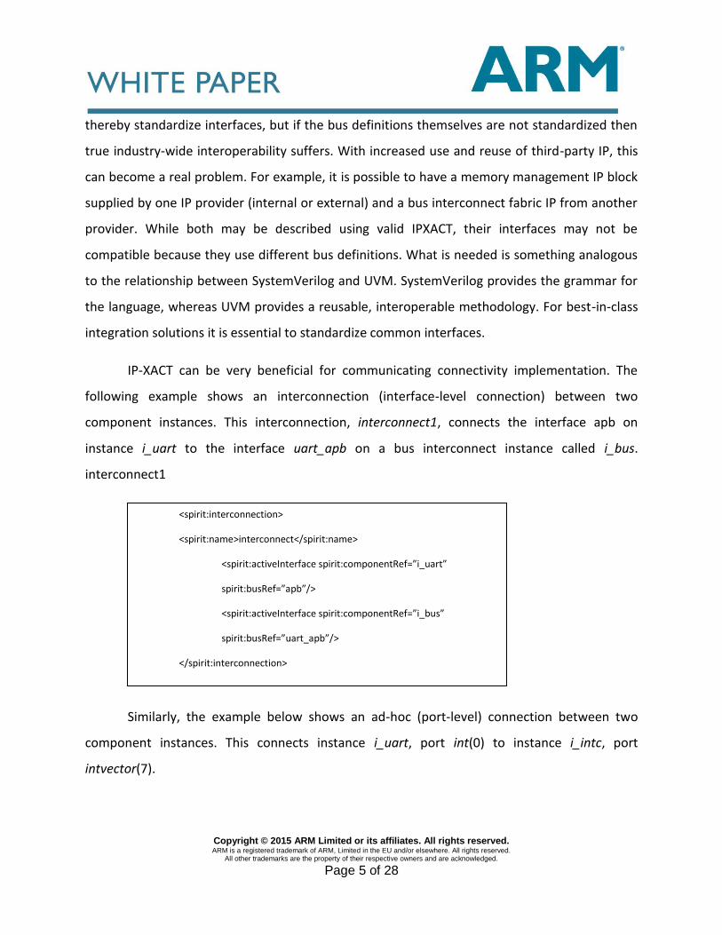
IP-XACT can be very beneficial for communicating connectivity implementation. The
following example shows an interconnection (interface-level connection) between two
component instances. This interconnection, interconnect1, connects the interface apb on
instance i_uart to the interface uart_apb on a bus interconnect instance called i_bus.
interconnect1
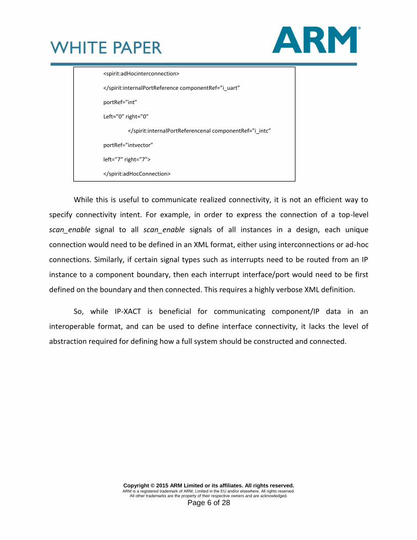
Similarly, the example below shows an ad-hoc (port-level) connection between two
component instances. This connects instance i_uart, port int(0) to instance i_intc, port
intvector(7).
<spirit:interconnection>
<spirit:name>interconnect</spirit:name>
<spirit:activeInterface spirit:componentRef=”i_uart”
spirit:busRef=”apb”/>
<spirit:activeInterface spirit:componentRef=”i_bus”
spirit:busRef=”uart_apb”/>
</spirit:interconnection>
Copyright © 2015 ARM Limited or its affiliates. All rights reserved. ARM is a registered trademark of ARM, Limited in the EU and/or elsewhere. All rights reserved.
All other trademarks are the property of their respective owners and are acknowledged.
Page 6 of 28
While this is useful to communicate realized connectivity, it is not an efficient way to
specify connectivity intent. For example, in order to express the connection of a top-level
scan_enable signal to all scan_enable signals of all instances in a design, each unique
connection would need to be defined in an XML format, either using interconnections or ad-hoc
connections. Similarly, if certain signal types such as interrupts need to be routed from an IP
instance to a component boundary, then each interrupt interface/port would need to be first
defined on the boundary and then connected. This requires a highly verbose XML definition.
So, while IP-XACT is beneficial for communicating component/IP data in an
interoperable format, and can be used to define interface connectivity, it lacks the level of
abstraction required for defining how a full system should be constructed and connected.
<spirit:adHocinterconnection>
</spirit:internalPortReference componentRef=”i_uart”
portRef=”int”
Left=”0” right=”0”
</spirit:internalPortReferencenal componentRef=”i_intc”
portRef=”intvector”
left=”7” right=”7”>
</spirit:adHocConnection>
Copyright © 2015 ARM Limited or its affiliates. All rights reserved. ARM is a registered trademark of ARM, Limited in the EU and/or elsewhere. All rights reserved.
All other trademarks are the property of their respective owners and are acknowledged.
Page 7 of 28
IP INTEGRATION SOLUTIONS
Considering the problems outlined previously, a possible recipe for an effective IP integration
solution is a methodology that:
1. Promotes the standardization of IP interfaces across the industry.
2. Provides powerful system assembly and connectivity capabilities by:
a. Enabling the full utilization of the industrystandard IP interfaces in the integration
process.
b. Providing users with the ability to very efficiently define full system assembly,
connectivity and configurability.
c. Offering flexibility when it comes to creating configurable systems.
d. Ensuring a high level of reusability and easy maintenance.
e. Enabling interoperability with other integration processes via IP-XACT.
f. Ensuring that the methodology is instantly usable by people familiar with the domain.
This paper will proceed to explore a solution that offers such a methodology through a
combination of standards such as IPXACT and a new and innovative rules-based integration
methodology. A current implementation of this methodology is demonstrated by Socrates
Weaver [7].
Copyright © 2015 ARM Limited or its affiliates. All rights reserved. ARM is a registered trademark of ARM, Limited in the EU and/or elsewhere. All rights reserved.
All other trademarks are the property of their respective owners and are acknowledged.
Page 8 of 28
A. IP standardization Methodology
It is important to employ an IP standardization methodology to ensure that IP is ‘integration-
ready’. One of the problems highlighted previously is a lack of industry-standard bus definitions
for common interfaces. The Spirit consortium developed an initial set of bus definitions that are
now available under the Accellera Systems Initiatives website [9]. Also, within Accellera, an IP-
XACT Best Practice group is working to develop bus definitions that can be used across the
industry as well as creating guidelines aimed at ensuring that bus definitions are more
standardized and interoperable. Some common bus definitions are provided by the owners of
the protocol standard. For instance, in the case of ARM IP, ARM provide bus definitions for the
AMBA® 1 protocol. [8]
The IP standardization process, also known as ‘IP Packaging’, has a number of elements:
It provides a mechanism to aggregate ports into interfaces to ease integration and
verification.
It provides the ability to standardize the hardware view of an IP. This can be considered a
standardization overlay, as it doesn’t affect RTL port names. Where there are 1 AMBA is the
registered trademark of ARM Limited in the EU and other countries multiple sources of an IP,
this can provide a standardized view across all sources that further facilitates integration.
The creation of this standardized view can be done by manually creating the IP-XACT
XML or through the use of metadata entry tools such as Socrates.
Copyright © 2015 ARM Limited or its affiliates. All rights reserved. ARM is a registered trademark of ARM, Limited in the EU and/or elsewhere. All rights reserved.
All other trademarks are the property of their respective owners and are acknowledged.
Page 9 of 28
B. Rules-Based Integration
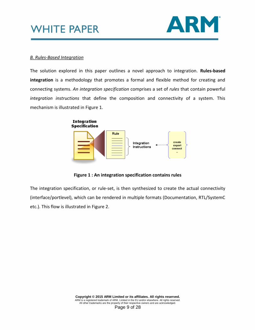
The solution explored in this paper outlines a novel approach to integration. Rules-based
integration is a methodology that promotes a formal and flexible method for creating and
connecting systems. An integration specification comprises a set of rules that contain powerful
integration instructions that define the composition and connectivity of a system. This
mechanism is illustrated in Figure 1.
Figure 1 : An integration specification contains rules
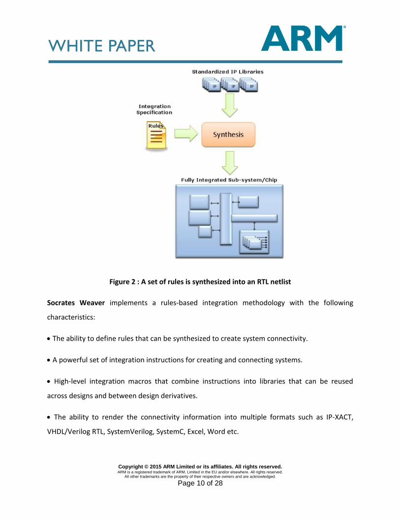
The integration specification, or rule-set, is then synthesized to create the actual connectivity
(interface/portlevel), which can be rendered in multiple formats (Documentation, RTL/SystemC
etc.). This flow is illustrated in Figure 2.
Copyright © 2015 ARM Limited or its affiliates. All rights reserved. ARM is a registered trademark of ARM, Limited in the EU and/or elsewhere. All rights reserved.
All other trademarks are the property of their respective owners and are acknowledged.
Page 10 of 28
Figure 2 : A set of rules is synthesized into an RTL netlist
Socrates Weaver implements a rules-based integration methodology with the following
characteristics:
The ability to define rules that can be synthesized to create system connectivity.
A powerful set of integration instructions for creating and connecting systems.
High-level integration macros that combine instructions into libraries that can be reused
across designs and between design derivatives.
The ability to render the connectivity information into multiple formats such as IP-XACT,
VHDL/Verilog RTL, SystemVerilog, SystemC, Excel, Word etc.
Copyright © 2015 ARM Limited or its affiliates. All rights reserved. ARM is a registered trademark of ARM, Limited in the EU and/or elsewhere. All rights reserved.
All other trademarks are the property of their respective owners and are acknowledged.
Page 11 of 28
The ability to extract integration metrics from the system, including connectivity progress,
complexity profiling etc.
The ability to split rules into different files to enable concurrent development.
Using rules, IPs can be integrated to create systems/subsystems using a powerful set of
instructions that instantiate and connect the component instances. A simple example of a rule
is shown below:
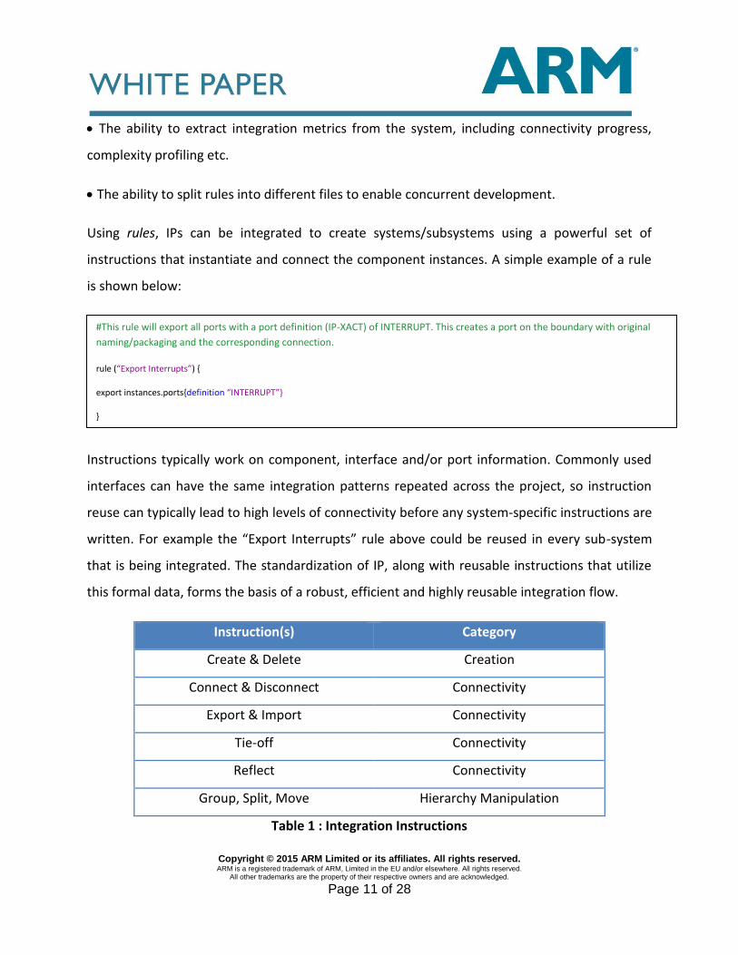
Instructions typically work on component, interface and/or port information. Commonly used
interfaces can have the same integration patterns repeated across the project, so instruction
reuse can typically lead to high levels of connectivity before any system-specific instructions are
written. For example the “Export Interrupts” rule above could be reused in every sub-system
that is being integrated. The standardization of IP, along with reusable instructions that utilize
this formal data, forms the basis of a robust, efficient and highly reusable integration flow.
Instruction(s) Category
Create & Delete Creation
Connect & Disconnect Connectivity
Export & Import Connectivity
Tie-off Connectivity
Reflect Connectivity
Group, Split, Move Hierarchy Manipulation
Table 1 : Integration Instructions
#This rule will export all ports with a port definition (IP-XACT) of INTERRUPT. This creates a port on the boundary with original
naming/packaging and the corresponding connection.
rule (“Export Interrupts”) {
export instances.ports{definition “INTERRUPT”}
}
Copyright © 2015 ARM Limited or its affiliates. All rights reserved. ARM is a registered trademark of ARM, Limited in the EU and/or elsewhere. All rights reserved.
All other trademarks are the property of their respective owners and are acknowledged.
Page 12 of 28
Weaver instructions (Table 1) are effectively a DomainSpecific Language (DSL) comprising
eleven intuitive instructions for system assembly scenarios such as creation, connection and
hierarchy manipulation. The recommended ordering of instructions in Weaver starts with
creating elements (e.g. instances), then connecting elements together using the connectivity
instructions, and finally performing hierarchy manipulation on the fully-connected system.
The instructions are detailed as follows:
The create instruction allows for the efficient creation of a range of design elements,
including components, instances, interfaces, ports, parameters and associated
properties, on specified elements. The delete instruction allows for the deletion of these
same elements.
The connect instruction is used to create port or interface connections
(interconnections) between instances, or between instances and the component
periphery. The disconnect instruction can be used to disconnect already existing
connections.
The tieoff instruction allows ports to be tied off to specified values. Source ports
(boundary inputs and instance outputs) can be tied open, while target ports (boundary
outputs, and instance inputs) can be tied off to specified logical values, including high,
low, hexadecimal, binary or octal values.
The export and import instructions allow ports to be exported to the boundary from
instances or imported from the boundary onto instances. The destination ports are
created (if they don’t already exist) on the boundary during export, and on the instance
during import. The source ports are connected to the newly-created ports and any port
or interface definition existing on the source port is replicated on the created port.
Copyright © 2015 ARM Limited or its affiliates. All rights reserved. ARM is a registered trademark of ARM, Limited in the EU and/or elsewhere. All rights reserved.
All other trademarks are the property of their respective owners and are acknowledged.
Page 13 of 28
The reflect instruction allows ports to be reflected from one instance to another.
Again, the destination ports are created if they don’t already exist. The reflect
instruction is extremely useful for automatically creating the boundary of infrastructure
components such as NIC, bridge components or glue logic.
The group instruction enables hierarchy manipulation by grouping specified instances
into a new layer of hierarchy while maintaining connectivity. A new component is
created to contain the specified instances. The split instruction is the opposite of group.
In this case, a layer of hierarchy containing instances is removed, bringing the instances
contained within it up to the current level. Again, full connectivity is maintained.
Each of these instructions operates on specified design elements such as components,
instances, ports or interfaces. A key requirement is to have a flexible selection mechanism to be
able to specify the exact target(s) for the instruction as well as being able to control some
aspects of the instruction’s behaviour. For instance, it might be useful to define, in a single
statement, that all AMBA reset signals (presetn, hresetn, aresetn etc.) are tied to a particular
reset source. This selection mechanism is the subject of the next topic.
1) Weaver Selection Mechanism
All of the Weaver instructions follow the same general format. They use one or more selection
expressions, which provide powerful filtering & regular expression features.
Copyright © 2015 ARM Limited or its affiliates. All rights reserved. ARM is a registered trademark of ARM, Limited in the EU and/or elsewhere. All rights reserved.
All other trademarks are the property of their respective owners and are acknowledged.
Page 14 of 28
In the example shown, the connect instruction is followed by two selection expressions. The
selection expressions use dotted notation format between elements to provide flexible
selection of all component elements combined with powerful filtering & regular expression
support. The selections can also be filtered or constrained using different attributes such as:
IP-XACT bus interface and port definitions
Port direction or interface role
User-defined properties
Connectivity status
Some sample instructions and selection expressions are provided below:
Within selection expressions, any string value can support regular expressions and variable
substitutions. This allows for very powerful connectivity intent to be specified. For instance:
Export all ports of type ‘INTERRUPT’ to the top level
Tie-off all ports of type ‘CLKEN’ to high
Connect reset_l to all ports of type ARESETN or PRESETn and HRESETn
Export ports ending in “_pad” from any instance that contains the text “uart” to the
top-level
#This will export all unconnected ports on all instances containing ‘uart’. It will create a corresponding port on the
component boundary and a connection to the port.
Export instances(“.*uart.*”).ports{connected :false}
#Tieoff all port mapped to CLKEN signal of any bus definition to ‘1’
Tieoff instances.ports{definition “CLKEN”}, :HIGH
Copyright © 2015 ARM Limited or its affiliates. All rights reserved. ARM is a registered trademark of ARM, Limited in the EU and/or elsewhere. All rights reserved.
All other trademarks are the property of their respective owners and are acknowledged.
Page 15 of 28
Group all components instances that have a property ‘Power_Domain’ called “core” or
“PD1” together.
2) Controlling Instruction Behaviour
Many of the instructions have options that refine how the instruction should operate. For
example a :port_name option allows the name of the created port to be controlled when
exporting, importing or reflecting ports. It is possible to build up a created port name from
source port names, directions, instance and interface names e.g. “${instance}_{port}” will prefix
an exported port with the name of the instance it comes from. With this type of flexibility the
following examples of connectivity intent can be realized.
Export ports ending in “_pad” from all instances to the top level of a sub-system, prefix the
port name with the instance and suffix it with the port direction.
Export ports from on SDRAM controller instance to the top level but remove the “sdram_”
from the port name.
Each instruction has its own specific options. For instance, there is a match_width connectivity
option that determines how connectivity is made if the port widths don’t match.
It is also possible to put conditional statements around rules and instructions. This is
particularly powerful when constructing highly configurable systems as it allows users to
configure the system composition and resulting connectivity. This also extremely useful for
creating derivative designs.
Copyright © 2015 ARM Limited or its affiliates. All rights reserved. ARM is a registered trademark of ARM, Limited in the EU and/or elsewhere. All rights reserved.
All other trademarks are the property of their respective owners and are acknowledged.
Page 16 of 28
3) Hierarchy
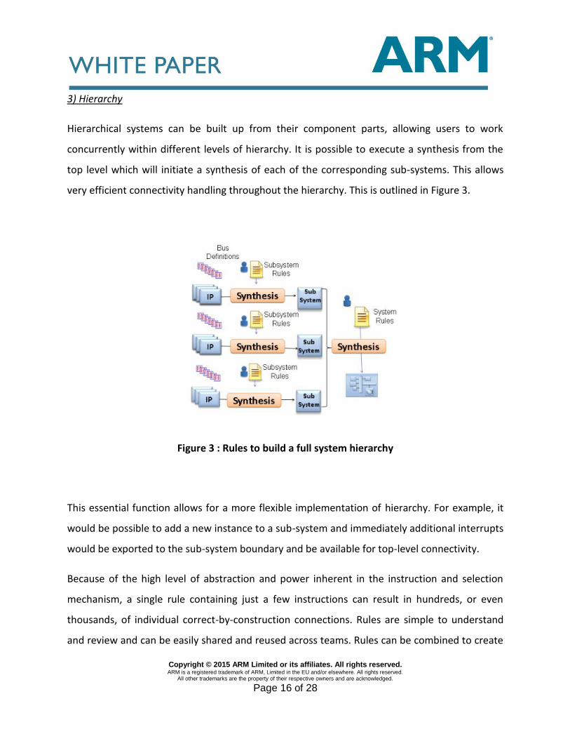
Hierarchical systems can be built up from their component parts, allowing users to work
concurrently within different levels of hierarchy. It is possible to execute a synthesis from the
top level which will initiate a synthesis of each of the corresponding sub-systems. This allows
very efficient connectivity handling throughout the hierarchy. This is outlined in Figure 3.
Figure 3 : Rules to build a full system hierarchy
This essential function allows for a more flexible implementation of hierarchy. For example, it
would be possible to add a new instance to a sub-system and immediately additional interrupts
would be exported to the sub-system boundary and be available for top-level connectivity.
Because of the high level of abstraction and power inherent in the instruction and selection
mechanism, a single rule containing just a few instructions can result in hundreds, or even
thousands, of individual correct-by-construction connections. Rules are simple to understand
and review and can be easily shared and reused across teams. Rules can be combined to create
Copyright © 2015 ARM Limited or its affiliates. All rights reserved. ARM is a registered trademark of ARM, Limited in the EU and/or elsewhere. All rights reserved.
All other trademarks are the property of their respective owners and are acknowledged.
Page 17 of 28
more complex structures and stored in libraries that can be used and reused across teams or
companies.
CASE STUDY: ARM-BASED SYSTEM
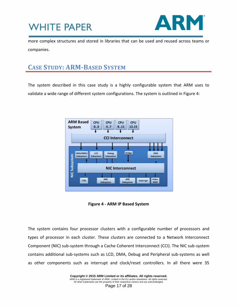
The system described in this case study is a highly configurable system that ARM uses to
validate a wide range of different system configurations. The system is outlined in Figure 4:
Figure 4 - ARM IP Based System
The system contains four processor clusters with a configurable number of processors and
types of processor in each cluster. These clusters are connected to a Network Interconnect
Component (NIC) sub-system through a Cache Coherent Interconnect (CCI). The NIC sub-system
contains additional sub-systems such as LCD, DMA, Debug and Peripheral sub-systems as well
as other components such as interrupt and clock/reset controllers. In all there were 35
Copyright © 2015 ARM Limited or its affiliates. All rights reserved. ARM is a registered trademark of ARM, Limited in the EU and/or elsewhere. All rights reserved.
All other trademarks are the property of their respective owners and are acknowledged.
Page 18 of 28
independent IPs to be integrated. The AMBA® protocols within the system included APB™,
AHB™, AHB-Lite™, AXI™, ATP™, LPI™, AXI4™, APB4™, ACE™ and ACELite™2
This system in structural Verilog (netlist) format consists of roughly 12,000 lines of code. Using
manual coding this type of system would typically take two people 6-7 weeks to code in Verilog.
A. IP Standardization
Using the rules-based methodology, the first step was to ensure that the IP interfaces were
standardized. Roughly half of the IP blocks had IP-XACT definitions utilizing 109 bus definitions.
The remaining IPs required the creation of an additional 23 bus definitions. This IP packaging
process was a once-off task for each IP. The packaging of each IP, including the creation of
relevant bus interfaces, took 1-2 hours.
B. Concurrent IP Integration
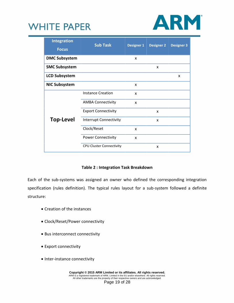
From an integration perspective, three engineers were tasked to put the different systems
together, working within 2 APB, AHB, AHB-Lite, AXI, ATP, LPI,, AXI4, APB4, ACE and ACE-Lite are
the trademarks of ARM Limited in the EU and other countries. three levels of hierarchy. On
some of the systems, they needed to work concurrently. In order to facilitate this, the
integration activity was split into sub-tasks and delegated among the team. This meant that
some people owned the full integration of individual sub-systems and some shared a single
system. An example of the task delegation used is as follows:
Copyright © 2015 ARM Limited or its affiliates. All rights reserved. ARM is a registered trademark of ARM, Limited in the EU and/or elsewhere. All rights reserved.
All other trademarks are the property of their respective owners and are acknowledged.
Page 19 of 28
Integration
Focus Sub Task Designer 1 Designer 2 Designer 3
DMC Subsystem x
SMC Subsystem x
LCD Subsystem x
NIC Subsystem x
Top-Level
Instance Creation x
AMBA Connectivity x
Export Connectivity x
Interrupt Connectivity x
Clock/Reset x
Power Connectivity x
CPU Cluster Connectivity x
Table 2 : Integration Task Breakdown
Each of the sub-systems was assigned an owner who defined the corresponding integration
specification (rules definition). The typical rules layout for a sub-system followed a definite
structure:
Creation of the instances
Clock/Reset/Power connectivity
Bus interconnect connectivity
Export connectivity
Inter-instance connectivity
Copyright © 2015 ARM Limited or its affiliates. All rights reserved. ARM is a registered trademark of ARM, Limited in the EU and/or elsewhere. All rights reserved.
All other trademarks are the property of their respective owners and are acknowledged.
Page 20 of 28
Misc connectivity
Tie-offs
For the top-level integration, the task was split between two people, each in a different time
zone. Different integration subtasks were identified that could be performed independently
and concurrently without creating conflicts. One of these engineers became the top-level lead
and was responsible for instance creation and the partitioning of the sub-tasks. The
connectivity tasks were partitioned based on connectivity types e.g. AMBA, exports (signals
going to the boundary), interrupts, clock/reset/power and CPU Cluster. While rules files can
include other rules files, it was decided to define the rules independently and then do a merge
every so often. This merge was handled by Weaver.
At certain times during this development, the three designers were working in parallel
making changes within three levels of the hierarchy. In some cases a new sub-system was
introduced, in others an IP required a new version update.
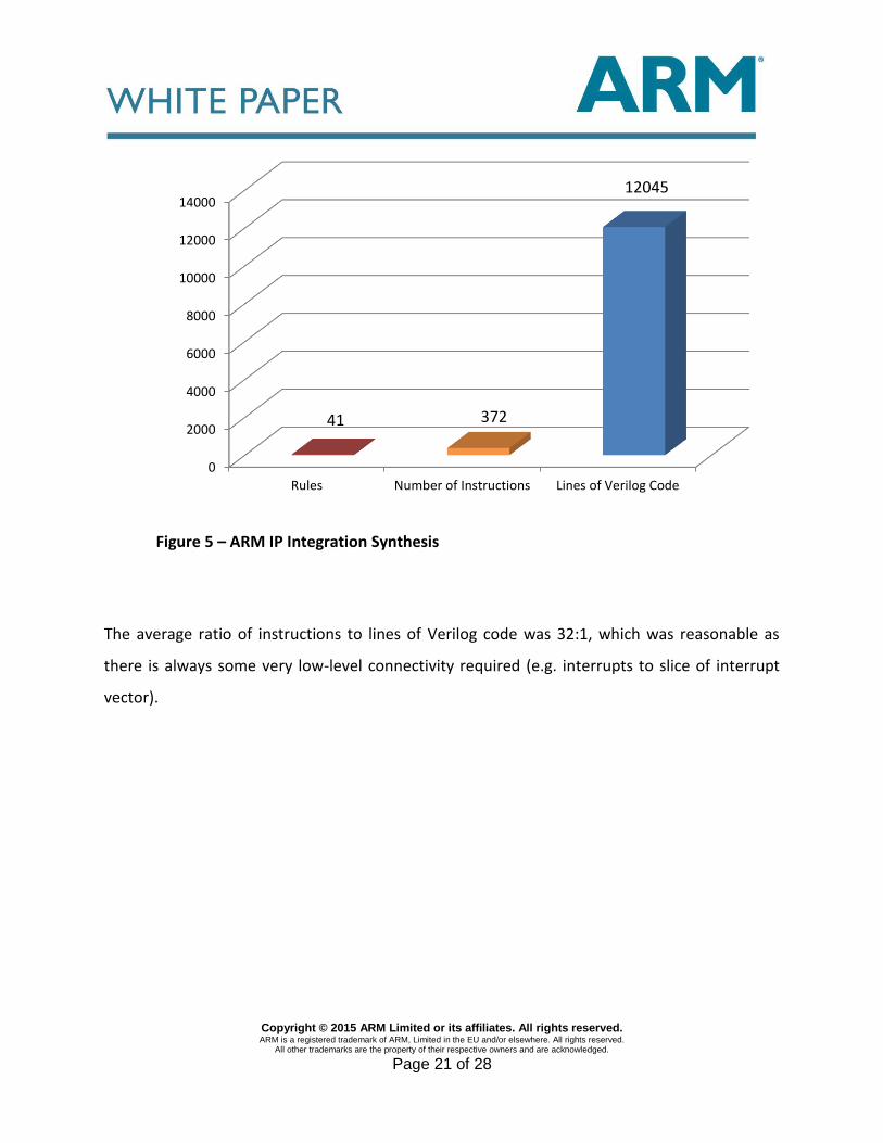
C. Result
The three levels of hierarchy were put together using 41 rules, with a total of 372
instructions. These were synthesized and netlisted to 12,045 lines of Verilog code as illustrated
in Figure 5:
Copyright © 2015 ARM Limited or its affiliates. All rights reserved. ARM is a registered trademark of ARM, Limited in the EU and/or elsewhere. All rights reserved.
All other trademarks are the property of their respective owners and are acknowledged.
Page 21 of 28
Figure 5 – ARM IP Integration Synthesis
The average ratio of instructions to lines of Verilog code was 32:1, which was reasonable as
there is always some very low-level connectivity required (e.g. interrupts to slice of interrupt
vector).
0
2000
4000
6000
8000
10000
12000
14000
Rules Number of Instructions Lines of Verilog Code
41 372
12045
Copyright © 2015 ARM Limited or its affiliates. All rights reserved. ARM is a registered trademark of ARM, Limited in the EU and/or elsewhere. All rights reserved.
All other trademarks are the property of their respective owners and are acknowledged.
Page 22 of 28
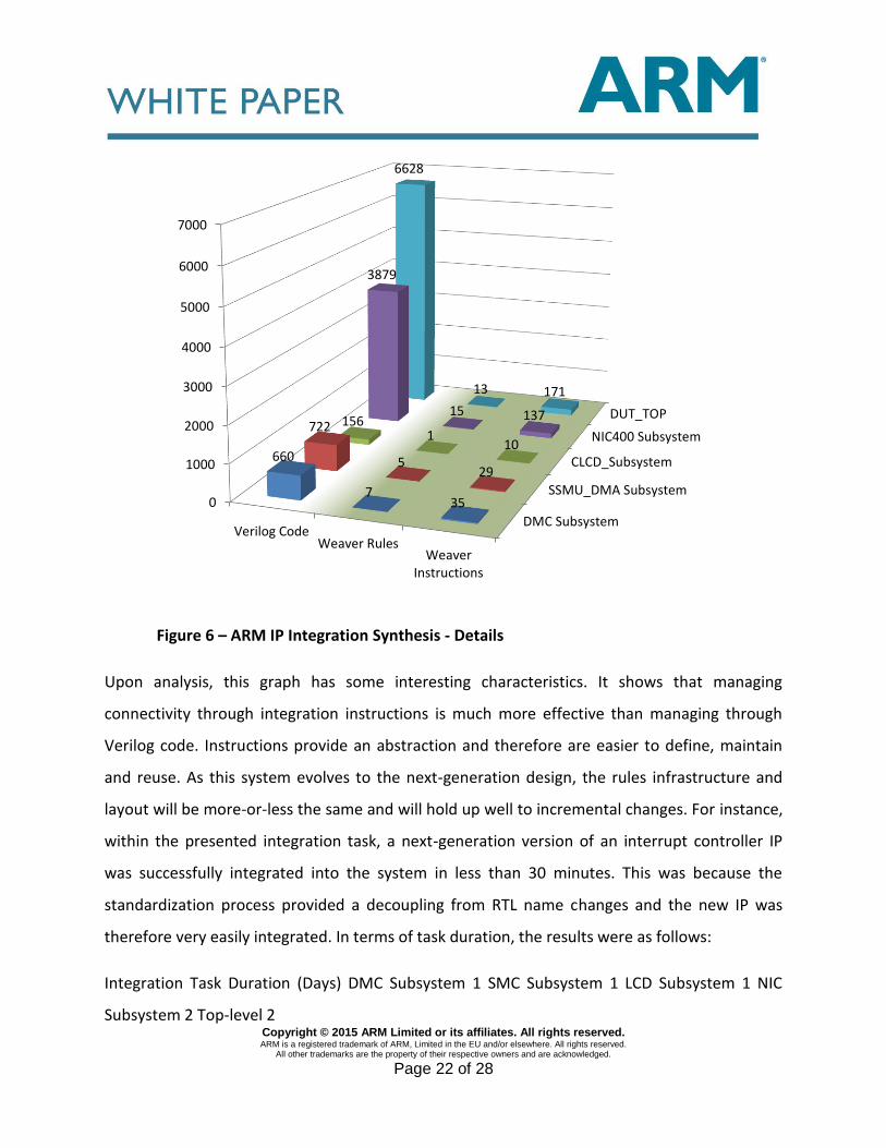
Figure 6 – ARM IP Integration Synthesis - Details
Upon analysis, this graph has some interesting characteristics. It shows that managing
connectivity through integration instructions is much more effective than managing through
Verilog code. Instructions provide an abstraction and therefore are easier to define, maintain
and reuse. As this system evolves to the next-generation design, the rules infrastructure and
layout will be more-or-less the same and will hold up well to incremental changes. For instance,
within the presented integration task, a next-generation version of an interrupt controller IP
was successfully integrated into the system in less than 30 minutes. This was because the
standardization process provided a decoupling from RTL name changes and the new IP was
therefore very easily integrated. In terms of task duration, the results were as follows:
Integration Task Duration (Days) DMC Subsystem 1 SMC Subsystem 1 LCD Subsystem 1 NIC
Subsystem 2 Top-level 2
DMC Subsystem
SSMU_DMA Subsystem
CLCD_Subsystem
NIC400 Subsystem
DUT_TOP
0
1000
2000
3000
4000
5000
6000
7000
Verilog CodeWeaver Rules
WeaverInstructions
660
7 35
722
5 29
156 1
10
3879
15 137
6628
13 171
Copyright © 2015 ARM Limited or its affiliates. All rights reserved. ARM is a registered trademark of ARM, Limited in the EU and/or elsewhere. All rights reserved.
All other trademarks are the property of their respective owners and are acknowledged.
Page 23 of 28
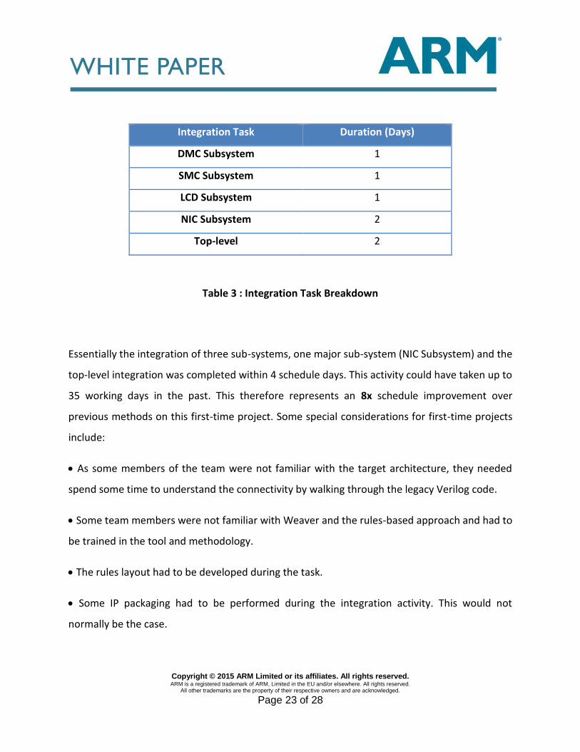
Integration Task Duration (Days)
DMC Subsystem 1
SMC Subsystem 1
LCD Subsystem 1
NIC Subsystem 2
Top-level 2
Table 3 : Integration Task Breakdown
Essentially the integration of three sub-systems, one major sub-system (NIC Subsystem) and the
top-level integration was completed within 4 schedule days. This activity could have taken up to
35 working days in the past. This therefore represents an 8x schedule improvement over
previous methods on this first-time project. Some special considerations for first-time projects
include:
As some members of the team were not familiar with the target architecture, they needed
spend some time to understand the connectivity by walking through the legacy Verilog code.
Some team members were not familiar with Weaver and the rules-based approach and had to
be trained in the tool and methodology.
The rules layout had to be developed during the task.
Some IP packaging had to be performed during the integration activity. This would not
normally be the case.
Copyright © 2015 ARM Limited or its affiliates. All rights reserved. ARM is a registered trademark of ARM, Limited in the EU and/or elsewhere. All rights reserved.
All other trademarks are the property of their respective owners and are acknowledged.
Page 24 of 28
Rules optimizations were performed as the integration progressed. This included the creation
of macros for commonly repeated tasks.
It is estimated that, once the methodology has been deployed, it is reasonable to expect a 10x-
15x improvement in schedule for new projects and 20x-30x for derivative projects. In fact, a
noticeable trend is using this methodology to manage derivatives by creating highly
configurable systems.
In terms of quality, the netlist synthesized from the rules was proven to be equivalent to a
netlist that had been previously manually created. There are a number of factors that drive the
quality higher. The rules-based instructions can utilize the standardized metadata so there is
less room for error. For example when connecting two AXI Interfaces using a connect
instruction, the AWADDR signal on the master can only connect to the AWADDR signal on the
slave. This is also true for tying off signals. Another factor that influences quality is that the
instructions are much clearer and easier to review than Verilog or VHDL code. This correct-by-
construction methodology means that there are fewer connectivity errors and system
verification teams can progress quickly to highervalue integration verification.
D. Creating Derivative Systems
The metrics detailed in the graphs represent the first IP integration using a rules-based
approach and represented a specific configuration. As this system is used as a validation target,
that will be used to validate a wide variety of system configurations, the next stage of the
process is to introduce this configurability at a user level. The goal of this process is to be able
to build complex and correct configurations of the full system within minutes.
Copyright © 2015 ARM Limited or its affiliates. All rights reserved. ARM is a registered trademark of ARM, Limited in the EU and/or elsewhere. All rights reserved.
All other trademarks are the property of their respective owners and are acknowledged.
Page 25 of 28
SUMMARY
Regardless of the tooling, in order to implement an efficient IP integration methodology, the
following recommendations apply:
1. Adopt an IP standardization methodology that is focused on standardization and
formalization of IP interfaces. Using an IP-XACT-based approach is highly recommended
as it promotes interoperability. It is also important to ensure that industry-standard bus
definitions and guidelines are used.
2. Use integration instructions that can utilize standardized IP metadata. The instruction
set should be simple to understand and should be at a level of abstraction above RTL or
IP-XACT.
3. Provide the ability to integrate through multiple levels of hierarchy allowing changes
deep within the hierarchy to be routed efficiently through the hierarchy. Also, provide
the ability to render new functional hierarchies.
4. Allow concurrent integration through the use of include files and enable the merging
of connectivity intent.
5. Adopt a format that allows for easy and efficient review of the resulting connectivity.
6. Provide the ability to be able to handle high levels of IP and system configurability.
7. Include a mechanism to formally prove that the desired connectivity has been
faithfully created.
8. Provide the ability to seamlessly swap in new variants of an IP and easily create
derivate subsystems whilst reusing the original integration intent.
Copyright © 2015 ARM Limited or its affiliates. All rights reserved. ARM is a registered trademark of ARM, Limited in the EU and/or elsewhere. All rights reserved.
All other trademarks are the property of their respective owners and are acknowledged.
Page 26 of 28
CONCLUSION
The case-study highlights that one of the fundamental aspects of this methodology is the
provision of standardized IP interfaces. Once standardized, it is possible to utilize this metadata
to perform powerful assembly and connectivity operations. Using a rules-based approach it is
possible reduce the overall SoC integration task by a factor of 15x-20x by employing a powerful
integration methodology that enables concurrent integration. The rules themselves are
specified using a very small instruction set (DSL) that can be instantly used by anyone familiar
with the integration domain.
This approach is also applicable to enabling more efficient HW/SW integration. This
methodology has also been successfully utilized as an engine for constructing configurable and
complex IP and has been used in applications such as crossbar generation, bridge insertion, I/O
Fabric creation, glue-logic insertion, power insertion, and for both SoC and FPGA-based flows.
Another trend is the linkage between high-level system specifications and this rules-based
capability. As the applications continue to grow, rules-based integration will continue to have a
dramatic impact on reducing schedule and increasing efficiency and quality.
Copyright © 2015 ARM Limited or its affiliates. All rights reserved. ARM is a registered trademark of ARM, Limited in the EU and/or elsewhere. All rights reserved.
All other trademarks are the property of their respective owners and are acknowledged.
Page 27 of 28
ACKNOWLEDGEMENT
The authors would like to extend thanks to ARM team in Bangalore, especially Sujatha Sriram,
for feedback provided on this project.
REFERENCES
[1] R. Goering, Cost of IP integration is rising dramatically, 2010:
http://www.cadence.com/Community/blogs/ii/archive/2010/03/29/isqedkeynote-putting-
some-numbers-to-cost-awaredesign.aspx?postID=43255
[2] R. Goering: EDAC- CEOs Identified integration as key challenge in IC design, 2012
http://community.cadence.com/cadence_blogs_8/b/ii/archive/2012/03/05/eda-ceos-speak-
out-3d-ics-ip-integration-low-power-and-more
[3] R. Goering, EDA CEOs speak out on IP integration , 2012
http://community.cadence.com/cadence_blogs_8/b/ii/archive/2012/03/05/eda-ceos-speak-
out-3d-ics-ip-integration-low-power-and-more
[4] R. Wawrzyniak, Integration in the top 9 chip design Challenges, EBN 2012
http://www.ebnonline.com/author.asp?section_id=1102&doc_id=24333 5
[5] J. Dewey, How to enable Microsoft Office and Visio for RTL design; 2007
http://www.eetimes.com/design/programmable-logic/4015122/How-toenable-Microsoft-
Office-and-Visio-for-RTL-design
[6] IP-XACT Technical Committee : http://www.accellera.org/activities/committees/ip-xact
Copyright © 2015 ARM Limited or its affiliates. All rights reserved. ARM is a registered trademark of ARM, Limited in the EU and/or elsewhere. All rights reserved.
All other trademarks are the property of their respective owners and are acknowledged.
Page 28 of 28
[7] Duolog Technologies, IP Integration & Chip Assembly
http://www.duolog.com/wpcontent/uploads/Socrates_Weaver_Datasheet_US.pdf
[8] ARM, CoreLink System IP & Design Tools for AMBA http://www.arm.com/products/system-
ip/amba/
[9] The SPIRIT Consortium - Reference BusDefs http://www.accellera.org/BusDefs