Lessons from the Pathfinder: KAT-7 to meerKAT to SKA T. L. Venkatasubramani T. L. Venkatasubramani Sub-System Manager – RFE (KAT-7) Sub-System Manager – STaN (meerKAT) Bruce Wallace SKA-SA Site Bid Manager SKA-South Africa SKA STaN CoDR, Jodrell Bank, 28-30 June 2011 STan CoDR Draft A
Transcript
Lessons from the Pathfinder: KAT-7 to meerKAT to SKA
T. L. VenkatasubramaniT. L. VenkatasubramaniSub-System Manager – RFE (KAT-7)
Sub-System Manager – STaN (meerKAT)
Bruce Wallace SKA-SA Site Bid Manager
SKA-South Africa
SKA STaN CoDR, Jodrell Bank, 28-30 June 2011STan CoDR Draft A
•Quite a lot has been learnt while building kat-7•These are currently being applied to meerKAT•The experience gained is of direct relevance to SKA
The approach in the presentation is to
Approach
The approach in the presentation is to give an overview without going into the full depth of a topic right now and to provide additional details on specific issues of interest during the discussions.
STan CoDR Draft A
•RF Broadband (1.2 to 1.95 GHz) analog optical fibre link over 5 km with required stability, repeatability, gain flatness, Signal-to-Noise and Head room for kat-7
Success of the effort can be judged by the fact that the overall system is in critical study on a 24x7 basis by the Commissioning and Operations Team for the past one year. There has been
STaN in SKA-SA
and Operations Team for the past one year. There has been negligible issues with the STaN after the initial hiccups were resolved by late 2010.
•40 GB digital link OVER ABOUT 11 km for meerKAT.•Long haul Data links over hundreds of kms for supporting KAT-7 and meerKAT requirements
STan CoDR Draft A
The SKA-SA Efforts for STaN has highly benefited by involving Industry
The key players are:
1. FOXCOMM, Israel (R&D on Standard Analog OTx-ORx Units
Industry Partners
1. FOXCOMM, Israel (R&D on Standard Analog OTx-ORx Units for Radio Astronomy needs and Supply)
2. CBi, South Africa (R&D on OF Cables, Supply)3. SIA, South Africa (Commissioning, Installation)4. Aurecon, South africa (Reticulation)5. NSN , Germany (OTx-ORx, Digital)
Note that the E-O and O -E segments of the receptor were treated as a part of the KAT-7 STaN
STan CoDR Draft A
The Karoo Site
STan CoDR Draft A
•RF Broadband (1.2 to 1.95 GHz) analog optical fibre link over 5 km with required stability, repeatability, gain flatness, Signal-to-Noise and Head room for kat-7
Success of the effort can be judged by the fact that the overall system is in critical study on a 24x7 basis by the Commissioning and Operations Team for the past one year. There has been
STaN in SKA-SA
and Operations Team for the past one year. There has been negligible issues with the STaN after the initial hiccups were resolved by late 2010.
•40 GBe digital link OVER ABOUT 11 km for meerKAT.•Long haul Data links over hundreds of kms for supporting KAT-7 and meerKAT requirements
STan CoDR Draft A
KAT-7 PathFinderA Bird’s Eye View
The Antenna Services Container (ASC), the
Node Point where fibre cables from seven
antennas meet and continue as a single
cableCabinet at Antenna pedestal
STan CoDR Draft A
KAT-7 PathFinder
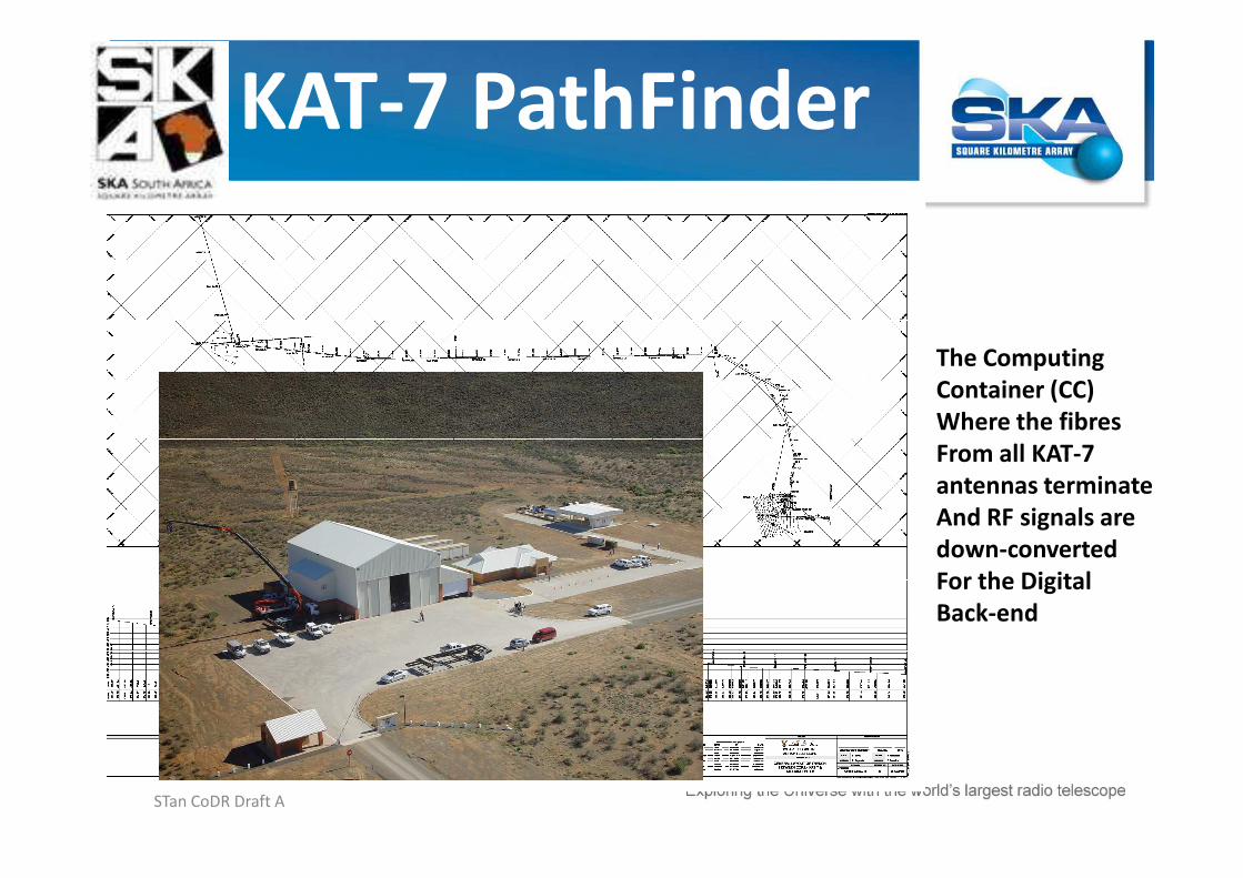
The Computing
Container (CC)
Where the fibres
From all KAT-7
The Reticulation Design
From all KAT-7
antennas terminate
And RF signals are
down-converted
For the Digital
Back-end
STan CoDR Draft A
•40 mm sub-ducts installed in 110 mm sleeves
•Conventional cable and blown fibre considered -conventional cable implemented due to ~50% cost
• 48 fibre Single Mode cable installed from ASC to CC for a distance of 5 kms without any joints.
•Man holes at a spacing of 500m was constructed to help in
Salient Features
•Man holes at a spacing of 500m was constructed to help in pulling the cable
•Length from ASC to antenna pedestal is around 200m. Composite cable with 12 Core MM and 12 SM fibres intalled.
• SM currently in operation for analog RF transmission and MM, for CAM purposes
•E2000 connectors selected as a standard
•All fibre buried at 1 m below surface to minimise temperature effects
STan CoDR Draft A
•Incoming quality inspection EXTREMELY IMPORTANT
•The initial behaviour of non-repeatable performance was traced to the non-concentricity in the pigtails and patch cords supplied, thanks to the investigation helped by the advanced facilities available at CBi
Lessons Learnt
helped by the advanced facilities available at CBi
•The whole batch was changed after one year of supply
•This was possible because acceptance procedures involving measurements with OTDR, Optical Loss and RF loss techniques were laid in the tender
LESSON: Include incoming inspection and verification of components in the planning stage!!
STan CoDR Draft A
DELINK the antenna pedestal availability and Buried Optical Fibreinstallation, test and release targetsFor meerKAT , the process is getting
Lessons Learnt
For meerKAT , the process is getting defined to ensure the above
LESSON: Eliminate linking two jobs with different time lines
STan CoDR Draft A
Be allergic to dust…. A Fibreoscopetells all!The process of “cleaning” an optical fibre connector sometimes only
Lessons Learnt
fibre connector sometimes only moves the dust around without ACTUALLY removing itLESSON: Do not be satisfied by just Doing… See and confirm.
STan CoDR Draft A
Avoid junction points with over-the -ground facilities like ASC if possible. •Note ASC was an ESSENTIAL NEED for the Fringe Finder phase of KAT -7 project. All the mid -coupler junctions at ASC have
Lessons Learnt
All the mid -coupler junctions at ASC have now been spliced.LESSON: If there is no need to do any checking at intermediate junction point/s it is better to splice, protect and BURY the joint – Concept to be followed for meerKAT
STan CoDR Draft A
The meerKAT STaN
CC
C
L-band Receiver
Fibre Junction box
DigitiserNoise
switching
UHF-band Receiver
CAM unit
CAM ethernet
Noise
switching
X-band Receiver
CAM unit
CAM ethernet
Noise
switching
Receiver2 fibre cable
Receiver1 fibre cable
Receiver
CAM
Rece
iver
CA
M
3
3
Digitiser fibre
cable
17
Feed Indexer
Vacuum
pump
CKey:Connector
interface
Fibre optic
cable
Conductive
CAM cables
CA
M e
thern
et
CA
M e
th
CAM
ethernet
The meerKAT StaN will
Have 18 fibres from each
Antenna focus to pedestal 2 cores - reference clock
2 cores - 1PPS
2x4 = 8 cores for digitised Data
6 spare to make 18 fibres
There will be 6 fibred used
at pedestal,
CC
Pedestal
L band Receiver
CAM fibre cable to focus
Receptor fibre cable
Receiver3 fibre cableCAM unit
CAM ethernet
Noise
switching
Receiver CAM
Data, clock,
PPS & CAM
fibres
Receptor CAM2
Data (8)
Clock(2)
1PPS(2)
14 (+10 spares = 24)
8
20
3
ACU RFI shielded box
Sw
itch
Position
controller
8
2
Receiver &
digitiser CAMPatch
Panel
17
14
1210
GM
compressor
TrenchesTo mini-subs
(circuit breaker monitoring)
C
Mini-sub
monitoring
eth
ernet
C
2
C
Yoke/Outside Pedestal
at pedestal, 2 for CAM and 4 spare
THUS A 24 SM FIBRE
NETWORK FOR EACH OF
THE 64 ANTENNAS TO A
COMMON LOCATION 12
KMS AWAY IS REQUIRED.
This is considered as a Low
Risk Option and actual
Usage can change as the
receiver design evolves
STan CoDR Draft A
The meerKAT STaN
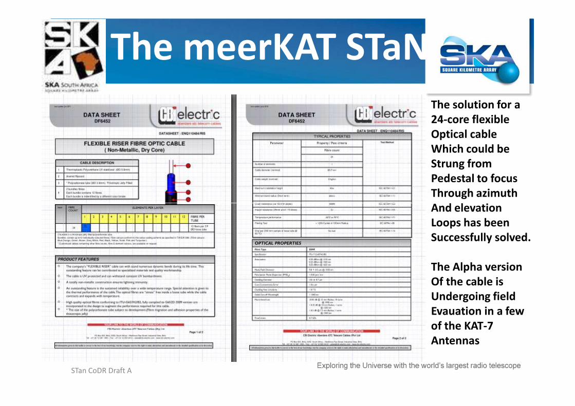
The solution for a
24-core flexible
Optical cable
Which could be
Strung from
Pedestal to focus
Through azimuth
And elevationAnd elevation
Loops has been
Successfully solved.
The Alpha version
Of the cable is
Undergoing field
Evauation in a few
of the KAT-7
Antennas
STan CoDR Draft A
The meerKAT STaN
A Christmas Tree
Structure has been
designed with sub-sub-
nodes, sub-nodes and
nodes through
which buried cables
originating from
each of the 64 antennaeach of the 64 antenna
pedestals congregate
into 4 nodes
with out any splicing.
The buried cable
continues from the 4
nodes to Karoo
Array Processor Building
(KPAB) to complete the
transport scheme
STan CoDR Draft A
The meerKAT KPAB
The design of the signal
Path ADC and following
digital Circuitry at
focus , pedestal (if
needed) and KPAB has
Been assigned to DBE
Sub-system ManagerSub-system Manager
Discussions with NSN is
In progress to evaluate
The suitability of their
Products for the
meerKAT signal chain
STan CoDR Draft A
1. A new 33 kV Powerline has been constructed from Carnarvon to the SKA Core site encompassing a MASS (Metal-Armoured Self Supporting) fibre optic cable implemented as the earth-wire.
2. SKA SA has established the SKA SA POP Station in Carnarvon.
The Long-Haul
POP Station in Carnarvon.
3. SANReN has implemented a 10 Gbit/s fibre “metro ring” from the SKA POP site in Carnarvon, connecting the Losberg Core Site and the Klerefontein Support Base. This will provide full flexibility between these three sites. The sites terminate in Cisco switches with DWDM functionality.
Carnarvon POP Site
STan CoDR Draft A
4. A contract has been placed by SANReN (South African National Research Network) on SA national operators Neotel / Broadband Infraco for the initial 10 Gbit/s connectivity from Cape Town to Carnarvon. The full fibre optic connectivity will be in place by end June 2011.
5. SANReN placed a contract on the SA national operator Telkom for a temporary capacity of 10 Mbit/s from Carnarvon to the SKA Cape Town Project Office to facilitate KAT-7 antenna commissioning
The Long-Haul
Town Project Office to facilitate KAT-7 antenna commissioning activities. This fibre link will be upgraded in future to provide a redundant fibre optic link. The link from Losberg to Cape Town office was commissioned in November 2010 enabling KAT-7 remote operations.
6. The SKA Cape Town Project Office will be connected into the new SANReN fibre optic DWDM Cape Town “metro ring” mid 2011. This will provide full DWDM fibre connectivity via the Infraco L/D network from SKA Core Site to Cape Town.
STan CoDR Draft A
The Long-Haul
STan CoDR Draft A
The Long-Haul
STan CoDR Draft A
1. The current fibre network provides the foundation for the future SKA transport network from the Core Site to Cape Town or Mtunzini for connectivity to the undersea cable systems.
2. Broadband Infraco will install an additional170 kms of fibre optic cable to provide a fully redundant DWDM fibre network from the MeerKAT Site to Cape Town (as per previous diagram). An additional fibre cable will be incorporated into the power supply system required for the SKA Core site.
The Long-Haul
required for the SKA Core site.
3. The initial Telkom SA link will be retained to provide an additional level of redundancy via a totally independent operator network
4. The fibre network will interface to the WACS (West African Cable System) submarine cable from Cape Town to Europe / United Kingdom with a capacity of 5.12 Tbit/s. 10/100 Gbit/s reserved for MeerKAT/SKA respectively. Redundancy to this system to Europe will be provided by East Coast cable systems such as SEACOM / EASY / SAFE cable systems.
STan CoDR Draft A
The Long-Haul
The African Under-sea
Cable System
STan CoDR Draft A
The three antenna cores and the antenna network spirals out to 180 kmswill be implemented as a private network. The fibre optic cable network will be installed in the most cost effective network for both electrical and data transport networks. Nokia Siemens Networks (NSN) are assisting with the development of equipment to meet the asymmetrical nature of the network but with fully management capability across all DWDM wavelengths.
The remote sites will be overlaid on the networks of three of the SA fibre
The Long-Haul
The remote sites will be overlaid on the networks of three of the SA fibre optic network operators. Discussions are in hand to develop the following options:
Access to dark fibre / utilise existing repeater infrastructure
Access to managed bandwidths
Access to servitudes / provision own electronics
The same process will be applied to the African Partner countries. A comprehensive report has been received from a UK-based consultancy to confirm the availability of fibre networks and/or managed bandwidth.
STan CoDR Draft A
De-link the implementation and commissioning frominfrastructure development, where possible, to avoiddelays and extended fibre commissioning times.
Always be prepared for bad products – ImplementIncoming Inspection and Verification process for allcomponents
Implement a large number of spare fibres, especially in
In summary……
Implement a large number of spare fibres, especially inbackhaul routes - the requirement grows!
Consider dust in arid conditions, especially duringconstruction periods (which normally align with fibrecommissioning periods). Implementation of gravelsurfaces was a great improvement.
Challenge: follow-up on all network builds and detail as-built records. Be ahead of the game to maintain in-houseconfidence in the record system!


![Very Long Baseline Interferometry with the SKA · 2014. 12. 19. · VLBI with the SKA Zsolt Paragi SKA Band SKA-core Bandwidth Remote tel. Baseline sens. Image noise SEFD [Jy] [MHz]](https://static.documents.pub/doc/80x56/60afd58c2cb342480e46c8a7/very-long-baseline-interferometry-with-the-ska-2014-12-19-vlbi-with-the-ska.jpg)


