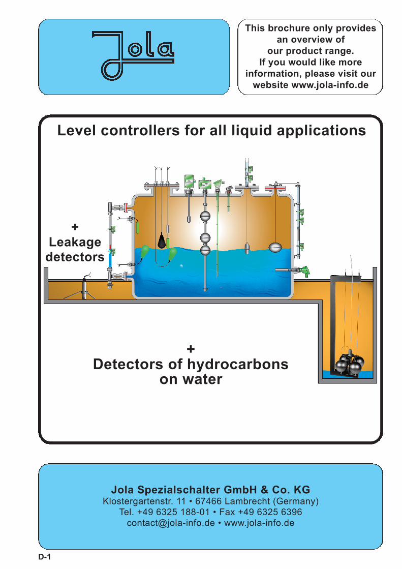
This brochure only provides an overview of our product range. If you would like more information, please visit our website www.jola-info.de Level controllers for all liquid applications D-1 + Leakage detectors + Detectors of hydrocarbons on water Jola Spezialschalter GmbH & Co. KG Klostergartenstr. 11 • 67466 Lambrecht (Germany) Tel. +49 6325 188-01 • Fax +49 6325 6396 [email protected] • www.jola-info.de
Technical data SSP 3/K/... SSP 1/K/... SI/SSP/NL/1/K/.../SSP/S3/K/... SSP/S1/K/... Variant 0 I M2 / II 2 G
Ex ia I Mb / Ex ia IIB T6 Gb
Application for standard applications for light current applications for use in intrinsically safeSwitching voltage between between circuits in mines susceptible
AC/DC 24 V and AC/DC 250 V AC/DC 1 V and AC/DC 42 V to firedamp or in potentiallySwitching current between between explosive atmospheres
AC 20 mA and AC 3 (1) A AC 0.1 mA and AC 100 (50) mA zone 1 or 2;or between or between EC type examination certificate
DC 20 mA and DC 100 mA DC 0.1 mA and DC 10 mA INERIS 03ATEX0149Switching capacity max. 350 VA max. 4 VA
Options for safety appl. –––– diodes (variant 1) or resistors (variant 2) on request
Recommended applicat. –––– via Jola protection relay via Jola Ex protection relay
see website under “Protection and alarm relays”
Float material PP
Seal material FPM; on request: EPDM
Float protection class IP68
Max. immersion depthof the float max. 10 m head of water at + 20°C
Connecting cable / application range /temperature range • black PVC cable, 3 x 0.75 (for SSP ./K/PVC and SI/SSP/NL/1/K/PVC/...), for use in:
water / used water / slightly aggressive liquids / oils without aromatic additives / fuel oil / diesel fuel,specific gravity: ≥ 0.82 g/cm³, T: + 8°C to + 60°C
• grey A05RN-F cable, 3 x 0.75 (for SSP ./K/RN and SI/SSP/NL/1/K/RN/...), for use in:water / used water / slightly aggressive liquids,specific gravity: ≥ 0.82 g/cm³, T: 0°C to + 60°C
• red-brown silicone cable (with low mechanical strength), 3 x 0.75(for SSP/S./K/SIL and SI/SSP/NL/1/K/SIL/...), for use in:water / certain other liquids, specific gravity ≥ 0.82 g/cm³,
T: 0°C to + 85°C for the types SSP/S./K/SIL,0°C to + 60°C for the type SI/SSP/NL/1/K/SIL ...
• green halogen-free PUR cable, 3 x 0.5 (for SSP/S./K/PUR and SI/SSP/NL/1/K/PUR/...), for use in: water / used water / slightly aggressive liquids / some oils without aromatic additives,
specific gravity: ≥ 0.82 g/cm³, T: 0°C to + 85°C for the types SSP/S./K/PUR and
0°C to + 60°C for the type SI/SSP/NL/1/K/PUR/...
• black CM cable, 3 x 0.75 (for SSP/S./K/CM and SI/SSP/NL/1/K/CM/...), for use in:water / certain acids / certain lyes, specific gravity: ≥ 1 g/cm³,
T: 0°C to + 85°C for the types SSP/S./K/CM and 0°C to + 60°C for the type SI/SSP/NL/1/K/CM/...
Connecting cable length 1 m, other cable lengths on request. When ordering, please always state the desired cable type and cable length.
Optional extras stuffing glands (see below) and stuffing glands andfixing weights fixing weight
Ø 28 mm x approx. 80 mm Ø 28 mm x approx. 82 mmmade of brass, stainless steel 316 Ti or PP made of PP
Level controllers
1
Stuffing glands:
G3/8, brass G1/2, brassG1/2, PP G1/2, stainless steel 316 Ti
G1, PP G1, stainless steel 316 TiG1, brass
Floating switch mounting only possiblefrom inside the tank
Floating switch mounting possible from outside the tank
These floating switches are designed for mountingfrom the side or from the top.
To ensure a correct switching, the cable must be fixed atthe required height using a stuffing gland, for example, inthe case of mounting from the side or using a fixing weightor a mounting pipe, for example, in the case of mountingfrom the top.
These units are not suitable for use in turbulent liquids (e.g. in stirrer tanks).
grey
(blu
e)br
own
blac
k
45±1
5
Ø 2
9
~ 3°±3°
133
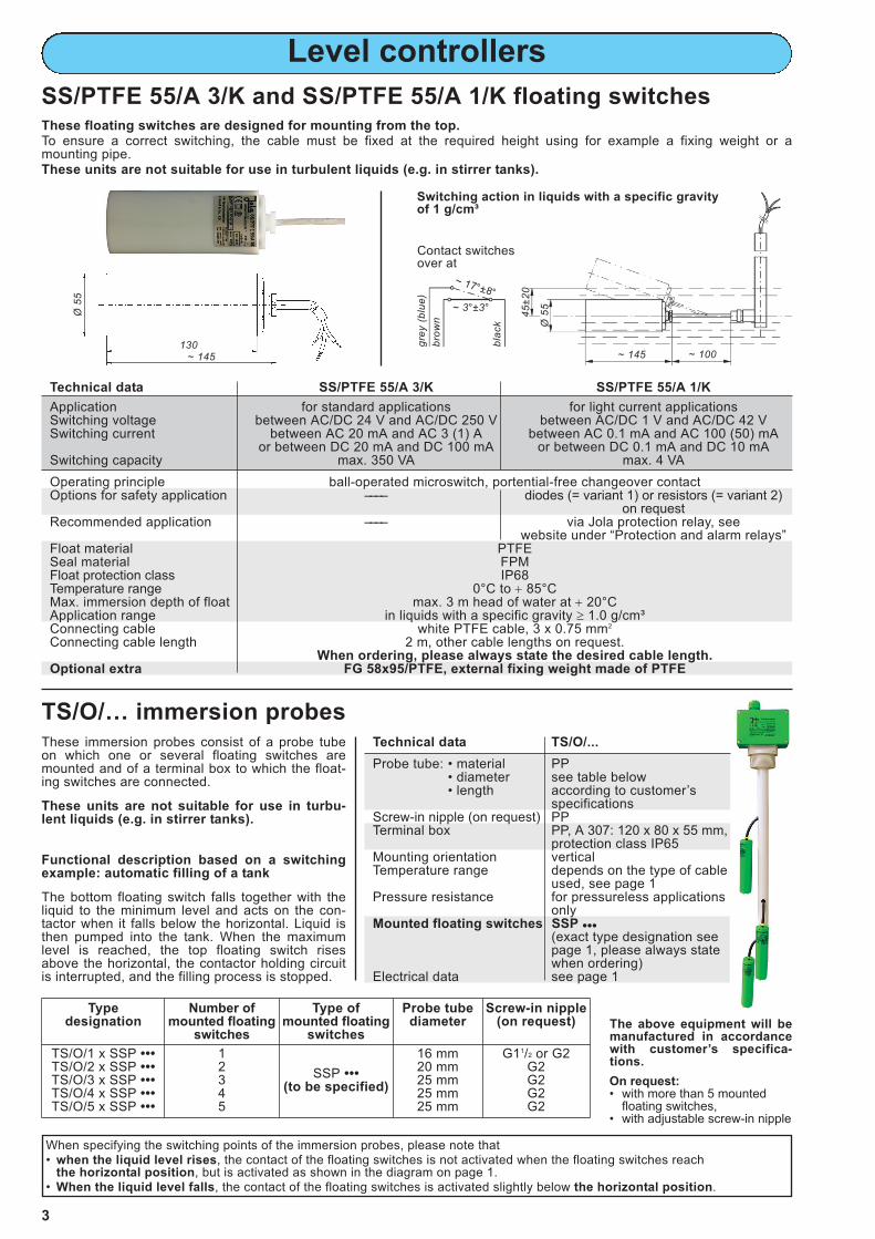
1) approx. 60 mm, but approx. 100 mm with CM cable
G1
1)
Switching action in liquids with a specific gravityof 1 g/cm³
~ 17°±8°
Contact switchesover at
SSP... and SI/SSP/NL/1/K/.../Variant 0 I M2 / II 2 GEx ia I Mb / Ex ia IIB T6 Gb floating switches
G1, stainless steel G1, PP
Technical data SSX 3/K/... SSX 1/K/... SI/SSX/LF/4/1/K/PURLF/SSX/S3/K/... SSX/S1/K/... Variant 0 I M2 / II 1 G
Ex ia I Mb / Ex ia IIC T6 Ga
Application for standard applications for light current applications for use in intrinsically safeSwitching voltage between between circuits in mines susceptible
AC/DC 24 V and AC/DC 250 V AC/DC 1 V and AC/DC 42 V to firedamp or in potentiallySwitching current between between explosive atmospheres
AC 20 mA and AC 3 (1) A AC 0.1 mA and AC 100 (50) mA zone 0, 1 or 2;or between or between EC type examination certificate
DC 20 mA and DC 100 mA DC 0.1 mA and DC 10 mA INERIS 03ATEX0149Switching capacity max. 350 VA max. 4 VA
Options for safety appl. –––– diodes (variant 1) or resistors (variant 2) on request
Recommended applicat. –––– via Jola protection relay via Jola Ex protection relay
see website under “Protection and alarm relays”
Float material PP antistatic (conductive) PP
Seal material FPM; on request: EPDM
Float protection class IP68
Max. immersion depthof float max. 10 m head of water at + 20°C
Connecting cable / application range / temperature range • black PVC cable, 3 x 0.75 (for SSX ./K/PVC), for use in:
water / used water / slightly aggressive liquids /oils without aromatic additives / fuel oil / diesel fuel,
specific gravity: ≥ 0.7 g/cm³, T: + 8°C to + 60°C
• grey A05RN-F cable, 3 x 0.75 (for SSX ./K/RN), for use in:water / used water / slightly aggressive liquids,specific gravity: ≥ 0.7 g/cm³, T: 0°C to + 60°C
• black CM cable, 3 x 0.75 (for SSX/S./K/CM), for use in:water / certain acids / certain lyes
specific gravity: ≥ 0.8 g/cm³, T: 0°C to + 85°C
• white PTFE cable, 3 x 0.75 (for SSX/S./K/PTFE), for use in:all liquids in which the float material PP
and the seal material FPM or EPDM are also resistant, specific gravity: ≥ 0.8 g/cm³, T: 0°C to + 85°C
Connecting cable length 2 m, other cable lengths on request. When ordering, please always state the desired cable type and cable length.
Optional extras • FG 58x100/Sg, external fixing weight made of cast steel,for liquids with a specific gravity ≥ 0.7 g/cm³
(not suitable for the PTFE cable)
• FG 55x80/E, external fixing weight made of stainless steel 316 Ti,
for liquids with a specific gravity ≥ 0.7 g/cm³
• IG, internal fixing weight (integrated in the float)for liquids with a specific gravity between 0.95 and 1.05 g/cm³
Level controllers
2
SSX... and SI/SSX/LF/4/1/K/PURLF/Variant 0 I M2 /II 1 G Ex ia I Mb / Ex ia IIC T6 Ga floating switches
These floating switches are designed for mounting from theside or from the top.To ensure a correct switching, the cable must be fixed at therequired height using a stuffing gland, for example, in the case of mounting from the side or using a fixing weight or a mounting pipe,for example, in the case of mounting from the top.These units are not suitable for use in turbulent liquids (e.g. instirrer tanks).
Switching action in liquids with a specific gravity of 1 g/cm³
~ 17°±8°
grey
(blu
e)br
own
blac
k
45±1
5
Ø 9
8~ 3°±3°
~ 165 ~ 80
Contact switchesover at
• black antistatic PURLF cable(with external conductive PUR
sheath) 4 G 0.75 (with 3 wires for the changeovercontact and 3 drain wires whichare twisted together for use aspotential equalisation cable),
for use in:water / used water / slightly
aggressive liquids, specific gravity: ≥ 0.7 g/cm³,
T: 0°C to + 60°C
• FG 55x93/Ex/KLF orFG 55x93/E/KLF/Ex,
external fixing weightmade of stainless steel 316 Ti,
for liquids with a specific gravity ≥ 0.7 g/cm³
Switching action of theSSX... or theSI/SSX/LF/4/1/K/PURLF/...with e x t e r n a lfixing weightmade of stainless steel(optional)
(idealized representation)
Switching action of theSSX... or theSI/SSX/LF/4/1/K/PURLF/...with i n t e r n a lfixing weight(optional)
Application for standard applications for light current applicationsSwitching voltage between AC/DC 24 V and AC/DC 250 V between AC/DC 1 V and AC/DC 42 VSwitching current between AC 20 mA and AC 3 (1) A between AC 0.1 mA and AC 100 (50) mA
or between DC 20 mA and DC 100 mA or between DC 0.1 mA and DC 10 mASwitching capacity max. 350 VA max. 4 VA
Operating principle ball-operated microswitch, portential-free changeover contactOptions for safety application –––– diodes (= variant 1) or resistors (= variant 2)
on requestRecommended application –––– via Jola protection relay, see
website under “Protection and alarm relays”Float material PTFESeal material FPMFloat protection class IP68Temperature range 0°C to + 85°CMax. immersion depth of float max. 3 m head of water at + 20°CApplication range in liquids with a specific gravity ≥ 1.0 g/cm³Connecting cable white PTFE cable, 3 x 0.75 mm2
Connecting cable length 2 m, other cable lengths on request.When ordering, please always state the desired cable length.
Optional extra FG 58x95/PTFE, external fixing weight made of PTFE
Technical data TS/O/...
Probe tube: • material PP• diameter see table below• length according to customer’s
specificationsScrew-in nipple (on request) PPTerminal box PP, A 307: 120 x 80 x 55 mm,
protection class IP65Mounting orientation verticalTemperature range depends on the type of cable
used, see page 1Pressure resistance for pressureless applications
onlyMounted floating switches SSP •••
(exact type designation see page 1, please always statewhen ordering)
Electrical data see page 1
Level controllers
These floating switches are designed for mounting from the top.To ensure a correct switching, the cable must be fixed at the required height using for example a fixing weight or a mounting pipe.These units are not suitable for use in turbulent liquids (e.g. in stirrer tanks).
3
SS/PTFE 55/A 3/K and SS/PTFE 55/A 1/K floating switches
~ 17°±8°
grey
(blu
e)br
own
blac
k
45±2
0
Ø 5
5~ 3°±3°
~ 145 ~ 100
Switching action in liquids with a specific gravity of 1 g/cm³
Contact switchesover at
These immersion probes consist of a probe tubeon which one or several floating switches aremounted and of a terminal box to which the float-ing switches are connected.
These units are not suitable for use in turbu-lent liquids (e.g. in stirrer tanks).
Functional description based on a switching example: automatic filling of a tank
The bottom floating switch falls together with the liquid to the minimum level and acts on the con-tactor when it falls below the horizontal. Liquid isthen pumped into the tank. When the maximumlevel is reached, the top floating switch risesabove the horizontal, the contactor holding circuitis interrupted, and the filling process is stopped.
The above equipment will bemanufactured in accordancewith customer’s specifica-tions.
When specifying the switching points of the immersion probes, please note that • when the liquid level rises, the contact of the floating switches is not activated when the floating switches reach
the horizontal position, but is activated as shown in the diagram on page 1.• When the liquid level falls, the contact of the floating switches is activated slightly below the horizontal position.
On request:• with more than 5 mounted
floating switches,• with adjustable screw-in nipple
Ø 5
5
~ 145130
Type designation
Number ofmounted floating
switches
Type of mounted floating
switches
Probe tubediameter
Screw-in nipple(on request)
TS/O/1 x SSP •••TS/O/2 x SSP •••TS/O/3 x SSP •••TS/O/4 x SSP •••TS/O/5 x SSP •••
12345
SSP •••(to be specified)
16 mm20 mm25 mm25 mm25 mm
G11/2 or G2G2G2G2G2
TS/O/… immersion probes
Technical data SM/P/3 SMG/P/3 SM/E/3 SMG/E/3
Application for standard applications. For light current applications on request.Switching voltage between AC/DC 24 V and AC/DC 250 VSwitching current between AC 20 mA and AC 5 A
or between DC 20 mA and DC 100 mASwitching capacity max. 1,000 VA
Ø 29 mm x 133 mm Ø 63 mm x 140 mm; Ø 28 mm x 120 mm Ø 63 mm x 140 mmon request: on request:
ball float Ø 85 mm ball float Ø 95 mmOn request: extensionpiece for the float horizontal or verticalBellows material PP stainless steel 316 TiScrew-in nipple PP, G1 stainless steel 316 Ti, G1Flange on request: square blind flange with G1 threaded hole made of
PP, PVDF or stainless steel 316 Ti stainless steel 316 Tior other flanges with any desired dimensions
Float, bellows andscrew-in nippleprotection class IP68Connection head PP with M 20 x 1.5 cable entry, protection class IP54;
on request: connection head made of cast aluminium, protection class IP54Mounting orientation horizontalTemperature range 0°C to + 90°C 0°C to + 100°C
(inside the connection head: 0°C to + 60°C)on request:
0°C to + 250°C(inside the connectionhead: 0°C to + 100°C)
Pressure resistance/test pressure for pressureless applications / test pressure: max. 2 bar at + 20°C
test pressure max. 2 bar only for versions on request: up towithout flange or with flange made of max. 4 bar at + 20°C
stainless steel; and ≥ 1.0 g/cm³ /with square flange made of PP or PVDF: 0 bar test pressure:
max. 6 bar at + 20°CApplication only for use in liquids with a specific gravity
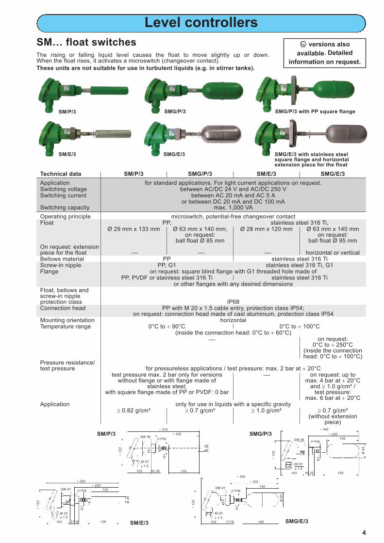
SM… float switchesThe rising or falling liquid level causes the float to move slightly up or down. When the float rises, it activates a microswitch (changeover contact).
These units are not suitable for use in turbulent liquids (e.g. in stirrer tanks).
versions also
available. Detailed
information on request.
~ 320
o-ring
G1 ~ 12
2
120
136103 17 19
~ 200SW 41
M 20x 1.5
~ 340
o-ring
Ø 6
3
G1 ~
122
140
159103 16 25
~ 220
SW 36
~ 315
o-ring
G1 ~
122
133103 16 25
~ 195SW 36
M 20 x 1.5 M 20
x 1.5
Ø 2
9
Ø 2
8
SM/E/3 SMG/E/3
SM/P/3 SMG/P/3
SMG/P/3
SMG/E/3
SM/P/3 SMG/P/3 with PP square flange
SMG/E/3 with stainless steelsquare flange and horizontalextension piece for the float
SM/E/3
~ 340
o-ring
Ø 6
3
G1 ~
122
140
156103 17 19
~ 220
SW 41
M 20 x 1.5
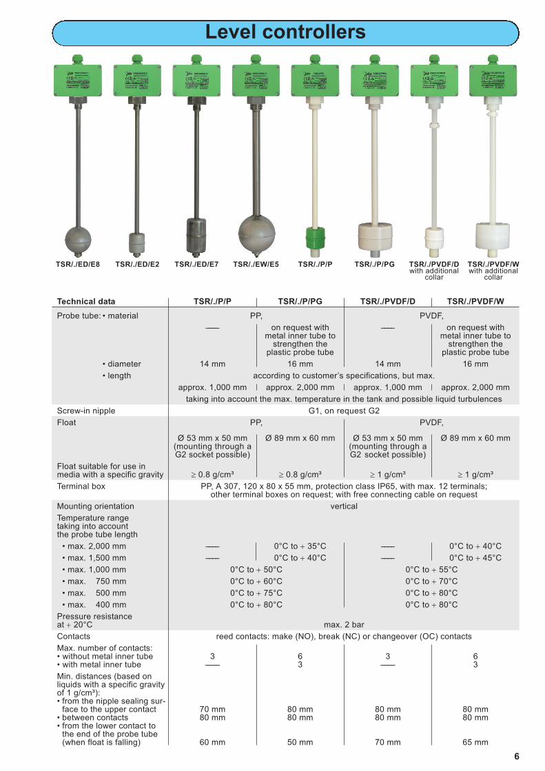
Technical data TSR/./ED/E8 TSR/./ED/E2 TSR/./ED/E7 TSR/./EW/E5
Probe tube: • material stainless steel 316 Ti
• diameter 12 mm 20 mm
• length according to customer’s specifications
Screw-in nipple G1/2, on request G1, G11/2 or G2; G1, on requestG11/2 or G2;
on request with reducing nipple made of malleable cast iron
R11/2 conical R2 conical R11/2 or R2 conical
Float stainless steel 316 Ti,
Ø 72 mm (ball) Ø 44.5 mm x 52 mm Ø 52 mm x 88 mm Ø 98 mm (ball) or(mounting through a (mounting through a Ø 97 mm x 80 mm
Float suitable for use in media with a specific gravity ≥ 0.7 g/cm³ ≥ 0.95 g/cm³ ≥ 0.7 g/cm³ ≥ 0.7 g/cm³
Terminal box PP, A 307, 120 x 80 x 55 mm, protection class IP65, with max. 12 terminals; other terminal boxes on request; with free connecting cable on request
Mounting orientation vertical
Temperature range − 20°C to + 100°C – 20°C to + 100°C;on request:
– 20°C to + 130°C
Pressure resistanceat + 20°C max. 12 bar (max. 3 bar for the heat-resistant version TSR/./EW/...), higher on request
Contacts reed contacts: make (NO), break (NC) or changeover (OC) contacts
Max. number of contacts 3 6, more on request
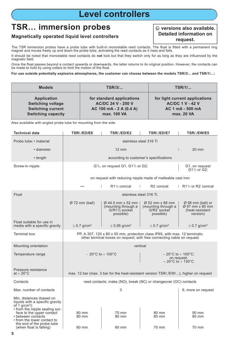
Min. distances (based on liquids with a specific gravity of 1 g/cm³):• from the nipple sealing sur-
face to the upper contact 80 mm 70 mm 80 mm 90 mm• between contacts 80 mm 80 mm 80 mm 80 mm• from the lower contact to
the end of the probe tube(when float is falling) 60 mm 60 mm 70 mm 70 mm
Level controllers
Models TSR/3/... TSR/1/...
Application for standard applications for light current applications
Switching voltage AC/DC 24 V - 250 V AC/DC 1 V - 42 V
Switching current AC 100 mA - 2 A (0.4 A) AC 1 mA - 500 mA
Switching capacity max. 100 VA max. 20 VA
Also available with angled probe tube for mounting from the side.
The TSR immersion probes have a probe tube with built-in monostable reed contacts. The float is fitted with a permanent ring magnet and moves freely up and down the probe tube, activating the reed contacts as it rises and falls.
It should be noted that monostable reed contacts do not lock but that they switch only for as long as they are influenced by themagnetic field.
Once the float passes beyond a contact upwards or downwards, the latter returns to its original position. However, the contacts canbe made to hold by using collars to limit the motion of the float.
For use outside potentially explosive atmospheres, the customer can choose between the models TSR/3/... and TSR/1/...:
versions also available.Detailed information on
request.
5
Technical data TSR/./P/P TSR/./P/PG TSR/./PVDF/D TSR/./PVDF/W
Probe tube: • material PP, PVDF,
–––– on request with –––– on request withmetal inner tube to metal inner tube to
strengthen the strengthen theplastic probe tube plastic probe tube
• diameter 14 mm 16 mm 14 mm 16 mm
• length according to customer’s specifications, but max.
approx. 1,000 mm approx. 2,000 mm approx. 1,000 mm approx. 2,000 mm
taking into account the max. temperature in the tank and possible liquid turbulences
Screw-in nipple G1, on request G2
Float PP, PVDF,
Ø 53 mm x 50 mm Ø 89 mm x 60 mm Ø 53 mm x 50 mm Ø 89 mm x 60 mm(mounting through a (mounting through aG2 socket possible) G2 socket possible)
Float suitable for use inmedia with a specific gravity ≥ 0.8 g/cm³ ≥ 0.8 g/cm³ ≥ 1 g/cm³ ≥ 1 g/cm³
Terminal box PP, A 307, 120 x 80 x 55 mm, protection class IP65, with max. 12 terminals;other terminal boxes on request; with free connecting cable on request
Mounting orientation vertical
Temperature rangetaking into accountthe probe tube length
• max. 2,000 mm –––– 0°C to + 35°C –––– 0°C to + 40°C
• max. 1,500 mm –––– 0°C to + 40°C –––– 0°C to + 45°C
• max. 1,000 mm 0°C to + 50°C 0°C to + 55°C
• max. 750 mm 0°C to + 60°C 0°C to + 70°C
• max. 500 mm 0°C to + 75°C 0°C to + 80°C
• max. 400 mm 0°C to + 80°C 0°C to + 80°C
Pressure resistance at + 20°C max. 2 bar
Contacts reed contacts: make (NO), break (NC) or changeover (OC) contacts
Max. number of contacts:• without metal inner tube 3 6 3 6• with metal inner tube –––– 3 –––– 3
Min. distances (based on liquids with a specific gravity of 1 g/cm³):• from the nipple sealing sur-
face to the upper contact 70 mm 80 mm 80 mm 80 mm• between contacts 80 mm 80 mm 80 mm 80 mm• from the lower contact to
the end of the probe tube(when float is falling) 60 mm 50 mm 70 mm 65 mm
Pipe clip material and pipeclip diameter (supplement ofthe type designation) • 28 = with stainless steel pipe clip,
for tube with outer Ø of 28 mm• 32 = with PP pipe clip, on request with stainless steel pipe clip,
for tube with outer Ø of 30 to 32 mm• 40 = with stainless steel pipe clip,
for tube with outer Ø of 35 to 40 mm• 60 = with stainless steel pipe clip,
for tube with outer Ø of 50 to 70 mm
Mounting orientation vertical (cable entry must point downwards)
Temperature range + 1°C to + 60°C
Level controllers
7
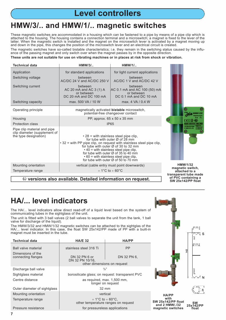
These magnetic switches are accommodated in a housing which can be fastened to a pipe by means of a pipe clip which isattached to the housing. The housing contains a connection terminal and a microswitch; a magnet is fixed to the lever of thelatter. When the magnetic switch is installed and the magnet on the microswitch lever is activated by a magnet moving upand down in the pipe, this changes the position of the microswitch lever and an electrical circuit is created.
The magnetic switches have so-called bistable characteristics; i.e. they remain in the switching status caused by the influ-ence of the passing magnet and only switch over when the magnet passes by in the opposite direction.
These units are not suitable for use on vibrating machines or in places at risk from shock or vibration.
HMW/3/.. and HMW/1/.. magnetic switches
HA/... level indicatorsThe HA/... level indicators allow direct read-off of a liquid level based on the system of communicating tubes in the sightglass of the unit.
The unit is fitted with 3 ball valves (2 ball valves to separate the unit from the tank, 1 ballvalve for discharge of the liquid).
The HMW/3/32 and HMW/1/32 magnetic switches can be attached to the sightglas of theHA/... level indicator. In this case, the float SW 25x142/PP made of PP with a built-inmagnet must be inserted in the tube.
HMW/1/32 magnetic switch,
attached to a transparent tube made
of PVC containing a SW 25x142/PP float
SW25x142/PP
float
HA/PPwith
SW 25x142/PP floatand 2 HMW/./32
magnetic switches
142
24
Ø 23.5
N
S
gree
n
red
142
24
Ø 25.5
N
S
versions also available. Detailed information on request.
Technical data NVM/PP/C NVM/PP/B
Float • material PP• dimensions Ø 63 mm x 140 mm Ø 85 mm
Float rod • material stainless steel 316 Ti or titanium• diameter 6 mm• length as required,
measured from the nipple sealing surfaceand without float (dimension L)
Max. length of the float rod for liquids with a specific gravity of 1 g/cm³ (dimension L)
• stainless steel 316 Ti rod 700 mm 800 mm• titanium rod 1,200 mm 1,200 mm
max. lengths for other specific gravitieson request
Magnet capsule material PP
Screw-in nipple • material PP, on request: stainless steel 316 Ti• dimensions G1
Option: installation flangefor mounting of the unit from outside the tank square flange made flange DN 100
of PP, PVDF or bigger made ofor stainless steel any material
Float rod guiding piece material POM; PTFE on request
Guide tube • material transparent PVC• dimensions Ø 32 mm x L + 65,
other lengths on request
Mounted magnetic switches HMW/3/32 or HMW/1/32
Max. number of magnetic switches as required and according to the
guide tube length
Mounting orientation vertical
Temperature range + 1°C to + 60°C
Pressure resistance for pressureless applications only
Option chemical protection composed of:• shrinkdown tubing made of PVDF
covering the float rod,• transition piece made of PP between
rod and float,• guiding piece for the float rodmade of PTFE instead of POM
Level controllers
8
~ 97
Ø 32
50
G1
Ø 63
S =
L -
3514
035
E +
30
Em
in. 5
0
~ 14
S =
L -
35
L +
65
2 L
+ E
+ 1
70
L+
E+
30
~ 14
~ 25
~ 90
15
E +
54
L ac
cord
ing
to c
usto
mer
’ssp
ecifi
catio
ns (m
ax. s
ee te
ch. d
ata)
sw 32
1 2 3
1 2 3
These level controllers are fitted with a float and a float rod to which a magnet isattached at the opposite end of the float.
The float follows the level of the liquid and moves up or down the float rod insertedthrough the screw-in threaded nipple of the unit. Above the nipple the guide tube isattached for the float rod and the magnet. Adjustable HMW/./32 magnetic switchesare mounted on the outside of the tube.
These magnetic switches have so-called bistable characteristics; i.e. they remain inthe switching status caused by the influence of the passing magnet and only switchover when the magnet passes by in the opposite direction.
These units are not suitable for use in turbulent liquids (e.g. in stirrer tanks) norfor use on vibrating machines or in places at risk from shock or vibration.
Electrical connection special angled plug for H07RN-F 1 x 1 mm2, protection class IP34
Mounting orientation vertical
Temperature range − 20°C (water: + 1°C) to + 80°C
Pressure resistance max. 10 bar at + 20°C max. 15 bar at + 20°C
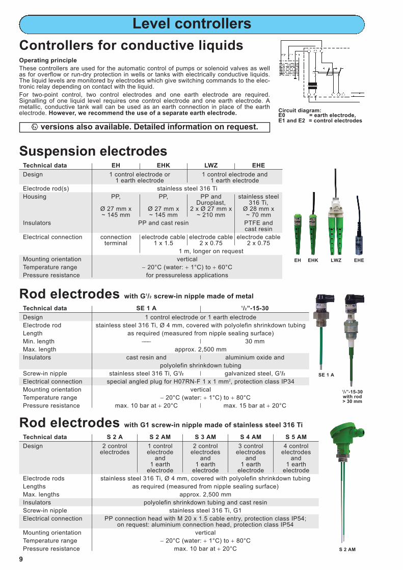
Rod electrodes with G1 screw-in nipple made of stainless steel 316 Ti
Technical data S 2 A S 2 AM S 3 AM S 4 AM S 5 AM
Design 2 control 1 control 2 control 3 control 4 controlelectrodes electrode electrodes electrodes electrodes
and and and and1 earth 1 earth 1 earth 1 earth
electrode electrode electrode electrode
Electrode rods stainless steel 316 Ti, Ø 4 mm, covered with polyolefin shrinkdown tubing
Lengths as required (measured from nipple sealing surface)
Max. lengths approx. 2,500 mm
Insulators polyolefin shrinkdown tubing and cast resin
Screw-in nipple stainless steel 316 Ti, G1
Electrical connection PP connection head with M 20 x 1.5 cable entry, protection class IP54;on request: aluminium connection head, protection class IP54
Mounting orientation vertical
Temperature range − 20°C (water: + 1°C) to + 80°C
Pressure resistance max. 10 bar at + 20°C
Level controllers
Controllers for conductive liquidsOperating principle
These controllers are used for the automatic control of pumps or solenoid valves as wellas for overflow or run-dry protection in wells or tanks with electrically conductive liquids.The liquid levels are monitored by electrodes which give switching commands to the elec-tronic relay depending on contact with the liquid.
For two-point control, two control electrodes and one earth electrode are required.Signalling of one liquid level requires one control electrode and one earth electrode. Ametallic, conductive tank wall can be used as an earth connection in place of the earthelectrode. However, we recommend the use of a separate earth electrode.
9
Circuit diagram:E0 = earth electrode,E1 and E2 = control electrodes
EH
1/2”-15-30with rod> 30 mm
SE 1 A
EHK LWZ EHE
S 2 AM
versions also available. Detailed information on request.
Level controllers
10
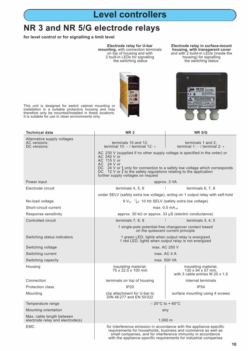
NR 3 and NR 5/G electrode relaysfor level control or for signalling a limit level
Electrode relay for U-bar mounting, with connection terminals
on top of housing and with2 built-in LEDs for signalling
the switching status
Electrode relay in surface-mounthousing, with transparent cover
and with 2 build-in LEDs (inside thehousing) for signallingthe switching status
Technical data NR 3 NR 5/G
Alternative supply voltagesAC versions: terminals 10 and 12; terminals 1 and 2;DC versions: terminal 10: − / terminal 12: + terminal 1: − / terminal 2: +
AC 230 V (supplied if no other supply voltage is specified in the order) orAC 240 V orAC 115 V orAC 24 V orDC 24 V or only for connection to a safety low voltage which correspondsDC 12 V or to the safety regulations relating to the applicationfurther supply voltages on request
1 single-pole potential-free changeover contact based on the quiescent current principle
Switching status indicators 1 green LED, lights when output relay is energized1 red LED, lights when output relay is not energized
Switching voltage max. AC 250 V
Switching current max. AC 4 A
Switching capacity max. 500 VA
Housing insulating material, insulating material,75 x 22.5 x 100 mm 130 x 94 x 57 mm,
with 3 cable entries M 20 x 1.5
Connection terminals on top of housing internal terminals
Protection class IP20 IP54
Mounting clip attachment for U-bar to surface mounting using 4 screwsDIN 46 277 and EN 50 022
Temperature range – 20°C to + 60°C
Mounting orientation any
Max. cable length between electrode relay and electrode(s) 1,000 m
EMC for interference emission in accordance with the appliance-specificrequirements for households, business and commerce as well as
small companies, and for interference immunity in accordancewith the appliance-specific requirements for industrial companies
This unit is designed for switch cabinet mounting orinstallation in a suitable protective housing and maytherefore only be mounted/installed in these locations. It is suitable for use in clean environments only.
Technical data PE PE-Z10 PEK PEK-Z10
Design 1 control electrode and 1 earth electrode
Sensitive elements 2 electrode plates made of stainless steel 316 Ti, each with 24 mm dia.
Housing PP and cast resin
Electrical connection screw-type / crimp connection connecting cable2 x 0.75, length 2 m,
on request:longer cable,
halogen-free connecting cable
Temperature range − 20°C to + 60°C, higher temperatures on request
Cable break monitoring without with without with
integrated Z10 cable break monitoring unit
Max. length of connecting cable between last electrode and electrode relay 1,000 m
Leakage detectors
11
Plate electrodes and cable electrodesFor signalling the presence of a conductive liquid caused, for example, by a burst pipe.
Plate and cable electrodes can, for example, be used on normally dry floors or false ceilings or in normally dry pipeline andcable ducts.
Cable electrodes can also be used alongside pipes or in dry double-pipe systems.
If the two electrode plates of a plate electrode or the two sensor cables of a cable electrode come into contact with a con-ductive liquid (e.g. water, acid etc.), an electrical contact is made and an alarm signal given.
PE, PE-Z10, PEK and PEK-Z10 plate electrodes
PE or PE-Z10,sensor side
Use of a plate electrode for leakagedetection on a floor
Application example
PE-Z10,connection side
PEK-Z10
versions also available. Detailed information on request.
Leakage detectors for conductive and non-conductive liquids also available. See p. 14.
The PE and PEK plate electrodes may only be connected to the Leckstar 5 electrode relay.
Only one PE-Z10 or one PEK-Z10 plate electrode or a plate electrode combination consisting of one or more PE +one PE-Z10 or consisting of one or more PE + one PEK-Z10 may be connected to the Leckstar 101 electrode relay.The connection must be made as shown in the circuit diagrams on page 13.
These leakage detectors are alsoavailable in versions for direct
connection to a PLC, a small-scalecontrol system, a DDC controlleror a field bus coupling element. Detailed information on request.
PE or PE-Z10 PEK or PEK-Z10
36
36
35°
2
5
R=25
3Ø
24
Ø
10
~ 30
20Ø
64
35°
5
R=25
Ø 2
4Ø
10
Ø 6
4
For the detection of conductive liquids
36
2
320
Technical data KE KE-Z10
Design 1 control electrode and 1 earth electrode
Sensitive elements 2 sensor cables in form of 2 ropes made of stainless steel 316, each 3 mm in dia., each covered by a halogen-free protective polyester sheath;
length: 2 m each, shorter or longer on request
Max. length of sensor cables 100 m;if the sensor cables are wound round a pipe or tank, the possible lengths may be considerably shorter depending on the type and method of laying
Supplied mounting accessories 4 sensor cable spacers made of PP per metre of sensor cable
Electrical connection connecting cable 2 x 0.75, length: 2 m; on request:longer cable,
halogen-free connecting cable
Temperature range − 20°C to + 60°C, higher temperatures on request
Cable break monitoring without with
integrated Z10 cable break monitoring unit (for test purpose removable)to monitor the connecting cable and the sensor cables
Max. length of connecting cablebetween cable electrode andelectrode relay 1,000 m minus the length of the sensor cable pair
Leakage detectors
12
KE and KE-Z10 cable electrodes
Use of a cable electrode for leakage detection in a storeroom
Notice for the mounting of the cable electrode
The 2 sensor cables of the cable electrode must be mounted parallel to one another at a distance of approx. 2 cmusing the sensor cable spacers, as a greater or lesser spacing affects the response level of the system in the event ofleakage.
The KE cable electrode may only be connected to the Leckstar 5 electrode relay.
The KE-Z10 cable electrode may only be connected to the Leckstar 101 electrode relay.
These leakage detectors are alsoavailable in versions for direct
connection to a PLC, a small-scale control system, a DDC controller or a field bus
coupling element. Detailed information on request.
Application example
KE-Z10
KE
<_ 20
~ 63
<_ 25
0<_
250
~ 40
~ 65
connector
sens
or c
able
s
sensor cable, ~ 3 mm Ø
PP housingwithintegratedcable breakmonitoringunit
connectors
sensor cablespacer
sensor cablespacer
~ 40
~ 25
<_ 20
~ 40
~ 58
T = 20
~ 63
acc.
to cu
stom
er´s
spec
ificat
ions
se
nsor
cab
les
<_ 25
0<_
250
~ 40
~ 65
connectingcable
connectingcable
PPhousing
PPhousing
sensorcable, ~ 3 mm Ø
Technical data Leckstar 5 Leckstar 101
Alternative supply voltagesAC versions: terminals 15 and 16;DC versions: terminal 15: − / terminal 16: +
AC 230 V (supplied if no other supply voltage is specified in the order) orAC 240 V orAC 115 V orAC 24 V orDC 24 V or only for connection to a safety low voltage which correspondsDC 12 V or to the safety regulations relating to the applicationfurther supply voltages on request
Power input approx. 3 VAElectrode circuit terminals 7 and 8, under SELV (safety extra low voltage),
acting on 1 output relay with self-holdNo-load voltage 18 Veff 10 Hz SELV (safety extra low voltage)Short-circuit current max. 0.5 mA eff
Response sensitivity approx. 30 kΩ or approx. 33 µS (electric conductance)Cable break monitoring –––– via Zener diode (Z10) circuit at the end of
the sensor line (incorporated in thePE-Z10, PEK-Z10 or KE-Z10 electrodes)
Controlled circuit terminals 9, 10 and 11,1 single-pole potential-free changeover contact based
on the quiescent current principleSwitching status indicators • red LED permanently lit: • yellow LED flashing:
leakage alarm, cable break, output relay not energizedouput relay not energized • green LED permanently lit:
OK status, output relay energized• red LED permanently lit:
leakage alarm, output relay not energizedSwitching voltage max. AC 250 VSwitching current max. AC 4 ASwitching capacity max. 500 VAHousing insulating material, 75 x 55 x 110 mmConnection terminals on top of housingProtection class IP20Mounting clip attachment for U-bar to DIN 46 277 and EN 50 022Mounting orientation anyTemperature range − 20°C to + 60°CMax. cable length between electrode relay and electrode(s) 1,000 mEMC for interference emission in accordance with the appliance-specific
requirements for households, business and commerce as well assmall companies, and for interference immunity in accordance
with the appliance-specific requirements for industrial companies
Leakage detectors
13
Leckstar 5 and Leckstar 101 electrode relaysElectrode relays for U-bar mount-ing, with connection terminals ontop of housing, with switchableself-hold function and with built-inLED(s) for signalling the operatingstatus.
The units are designed for switchcabinet mounting or installation ina suitable protective housing andmay therefore only bemounted/installed in these loca-tions. They are suitable for use inclean environments only.
Self-hold:• If the switch for self-hold is switched on, an alarm is stored. The relay continues to signal the alarm even if the cause
of the alarm (e.g. the presence of water or a cable break) is no longer present, in other words, if the sensor is dry again orif the line has contact. The alarm is acknowledged by switching off the switch for self-hold.
• If the switch for self-hold is not switched on, the alarm is not maintained when the cause of the alarm has beenremedied.
Leckstar 101 circuit diagrams (position of contacts when Leckstar 101 without voltage)
Connection ofseveral plateelectrodes to oneLeckstar 101electrode relay -group alarm
Housing stainless steel 316 Ti and PTFE, PP and cast resin,Ø 28 mm x approx. 145 mm 74 mm x 46 mm x 76 mm
Connecting cable TPK cable 2 x 0.75 mm², length 5 m, longer cable on requestFunctional principle capacitive sensor with stainless steel capacitive sensor with gold-plated
cylindrical capacitor capacitor plates on epoxy resin backing material
Protection class for the electronics sealed in the housing IP65Response height from bottom edge of housing approx. 12 mm (depending on the dielectric constant of the liquid)Temperature range − 20°C to + 60°CLength of connecting cable between sensor and relay max. 1,000 m, longer on requestEMC for interference emission in accordance with the appliance-specific requirements
for households, business and commerce as well as small companies, and for interference immunity in accordance with the appliance-specific requirements for
industrial companiesMounting accessory stand made of stainless steel 316 Ti
Technical data Leckmaster 101
Alternative supply voltages see Leckstar ... relays on page 13Power input approx. 3 VAControl circuit terminals 6 and 8 under SELV (safety extra low voltage),
acting on 1 output relay with switchable self-holdSensor connectionNo-load voltage DC 8.4 V SELV (safety extra low voltage)Short-circuit current < 10 mAResponse sensitivity 1.5 mA 1.8 mACable break monitoring I < 0.15 mAControlled circuit terminals 9, 10 and 11, 1 single-pole potential-free changeover contact based on
the quiescent current principleSwitching status indicators • flashing yellow LED: cable break, output relay not energized,
• permanent green LED: OK status, output relay energized,• permanent red LED: leakage alarm, output relay not energized,
Switching voltage max. AC 250 VSwitching current max. AC 4 ASwitching capacity max. 500 VAHousing insulating material, 75 x 55 x 110 mmConnection terminals on top of housingProtection class IP 20Mounting clip attachment for U-bar to DIN 46 277 and EN 50 022Temperature range − 20°C to + 60°CMounting orientation anyMax. connecting cable lengthbetween sensor and relay 1,000 m, longer on requestEMC see above
14
Leakage detectors
With cable break monitoring and switchable self-hold, for connection of 1 COW orOWE 2/C sensor.
Switching unit for U-bar mounting, with connection terminals on top of housing, withswitchable self-hold function and with built-in LEDs for signalling the operating status.
This unit is designed for switch cabinet mounting or installation in a suitable protec-tive housing and may therefore only be mounted/installed in these locations. It issuitable for use in clean environments only.
Self-hold: If the switch for self-hold is switched on, an alarm is stored. Therelay continues to signal the alarm even if the cause of alarm (e.g. the presence ofoil) is no longer present. The alarm is reset by switching off the switch for self-hold.
If the switch for self-hold is not switched on, the alarm is not maintained whenthe cause of the alarm has been remedied.
COW and OWE 2/C sensors
COW
For the detection of conductive and non-conductive liquidsversions also available.
Detailed information on request.
Leckmaster 101 relay
COW and OWE 2/C sensors permit to detect all organic and inorganic liquids with a specific dielectric constant between 1.8and 109, for instance the presence of fuel oil on the floor of a tank room or in a collection tub located underneath a fuel oilburner. They should only be used in normally dry surroundings.A COW or OWE 2/C sensor is designed for connection to a Leckmaster 101 relay.The COW and OWE 2/C sensors can be mounted either upright on the floor (using a JOLA stand) or freely suspended by their cable above the floor.
OWE 2/C
Technical data ESA 2
Alternative supply voltages see Leckstar ... relays on page 13
Electrode circuit terminals 7 and 8 with SELV (safety extra low voltage), acting on 2 output relays without self-hold, where one can be reset if an alarm is activated
No-load voltage 9 Veff 10 Hz SELV (safety extra low voltage)
Controlled circuits terminals 12, 13 - output relay 1, terminals 9, 10 - output relay 2, potential-freenormally closed contacts based on the quiescent current principle,both activated in standby status.Output relay 1 (term. 12, 13) ) can be reset in the event of alarm. Output relay 2 (terminals 9, 10) retains its switching status as long as the alarm is given.
Acknowledgement output relay 1 (terminals 12, 13) can be reset via a built-in buttonor an external acknowledgement button (connection option at terminals 4 and 5)
Switching status indicator via two-colour LED:• LED lights permanently green: OK status, output relays energized,• LED flashes red: leakage alarm, output relays not energized,• LED lights permanently red: alarm acknowledged,
output relay 1 reset
All other technical data see Leckstar ... relays on page 13
Leakage detectors
02/2015
Technical data SCHE 2/T/GR SCHE 2/E SCHE 2/E (Variant ILS)
Design 1 control electrode and 1 earth electrodeElectrode rods 2 rods made of st. st. 316 Ti, each 4 mm in dia., covered with shrinkdown tubing made of
polyolefine PVDF or PTFEElectrode head PP stainless steel 316 TiConnection TPK cable, PTFE cable,
potted in electrode head; other cable on requestLength of connecting cable 2 m; longer connecting cable on requestMaterial of electrode holder,stabiliser plate and brackets PVC stainless steel 316 Ti or other stainless steelNo. of floats, float materialand float dimensions 4 floats made of
PP stainless steel 316 Ti stainless steel 316 Tiapprox. 85 mm Ø approx. 95 mm Ø approx. 130 mm Ø
Temperature range + 8°C to + 60°C − 20°C to + 90°CMax. length of connectingcable between relay andSCHE ... 1,000 m
Design
The SCHE … floating electrodes are made up of an upper section and a lower section. The upper section consists of an electrode holder and a rod electrode (whoseposition can be adjusted in the electrode holder) with one control electrode and oneearth electrode for alarm signalling. The lower section of the floating electrode ismade up of four floats and a stabilising plate.
Mode of operation and adjustment
The SCHE … floating electrode normally floats on a conductive liquid, such as water. It is connected to an electrode relay which supplies it with a low safety voltage. The height of the rod electrode is set in such a way that the two electrode rod tips are permanently underwater. Depending on the movement of the surface of the liquid, the rod electrode should be set further up or down. Although the two electrode rodtips should be permanently underwater, they should only just be underwater, so thatwhen a conductive liquid (water in our example) is overlaid by a non-conductive liquid (such as oil), a thin layer of the non-conductive liquid (oil) is sufficient to lift the electrode rod tips of the rod electrode fromthe conductive water layer into the non-conductive oil layer, to thus interrupt the current flowing from the electrode relay viathe rod electrode, and therefore to activate an alarm.
If, for example, oil flows onto a still water surface following a leak, exact setting of the rod electrode will ensure that an oillayer of only approx. 3 to 10 mm thickness is sufficient to interrupt the control current flowing via the rod electrode and acti-vate an alarm.
To ensure functionning of the SCHE … floating electrode, there must be a minimum liquid level of 80 mm to 130 mm(depending on model) above the floor. If this condition is not fulfilled, the two electrode rod tips will no longer beunderwater – in other words, they will not be electrically bridged by a conductive liquid. This will lead to normallyundesired alarm activation via the connected electrode relay. The only model with an alarm bridging contact for thiseventuality is the SCHE 2/E (Variant ILS).
The SCHE … floating electrodes are designed for connection to the ESA 2 electrode relay.
ESA 2 electrode relay
SCHE ... floating electrodes
Floating electrodesFor detection of a thin layer of non-conductive liquids with a lower specific gravity on top of conductiveliquids with a higher specific gravity, e.g. oil on water.
Th
e u
nit
s d
es
cri
be
d i
n t
his
do
cu
me
nta
tio
n m
ay
on
ly b
e i
ns
tall
ed
, c
on
ne
cte
d a
nd
sta
rte
d u
p b
y s
uit
ab
ly q
ua
lifi
ed
pe
rso
nn
el!
Su
bje
ct
to d
ev
iati
on
s f
rom
th
e d
iag
ram
s a
nd
te
ch
nic
al
da
ta.
Th
e d
eta
ils
in
th
is b
roc
hu
re a
re p
rod
uc
t s
pe
cif
ica
tio
n d
es
cri
pti
on
s a
nd
do
no
t c
on
sti
tute
as
su
red
pro
pe
rtie
s i
n t
he
le
ga
l s
en
se
.
versions also available. Detailed information on request.