Disclaimer: This document has been prepared by ARTC for internal use and may not be relied on by any other party without ARTC’s prior written consent. Use
of this document shall be subject to the terms of the relevant contract with ARTC.
ARTC and its employees shall have no liability to unauthorised users of the information for any loss, damage, cost or expense incurred or arising by reason of an unauthorised user using or relying upon the information in this document, whether caused by error, negligence, omission or
misrepresentation in this document.
This document is uncontrolled when printed. Authorised users of this document should visit ARTC’s intranet or extranet (www.artc.com.au) to access the latest version of this document.
Discipline: Engineering (Signalling) Category: Standard
Level Crossing Equipment ESC-03-01
Applicability
ARTC Network Wide CRIA (NSW CRN)
Primary Source
SC 03 01
Document Status
Version Date Reviewed Prepared by Reviewed by Endorsed Approved
1.2 13 August 2010 Standards Stakeholders Chief Operating Officer
Risk & Safety Committee 09/06/2009
Amendment Record
Version Date Reviewed Clause Description of Amendment
1.0 29 May 09 First issue. Supersedes Common Standard SC 03 01 v1.3
1.1 07 Oct 09 Disclaimer updated as per Risk & Safety Committee 14/09/2009. References to Common Signalling Construction Standards numbers updated to new numbering scheme.
1.2 13 August 2010 All Issued as final.
Engineering (Signalling) Standard ESC-03-01 Level Crossing Equipment Contents
Contents 1 General ................................................................................................... 4
1.10 Access Conditions ............................................................................. 7 1.11 Production of as constructed documentation ......................................... 7
2 Road Level Crossings .............................................................................. 8 2.1 General Requirements ....................................................................... 8 2.2 Light Units ....................................................................................... 8
2.2.1 Light Units – General ............................................................... 8 2.2.2 Light Units – LED .................................................................... 8
13 Appendix A: Drawings .......................................................................... 18 13.1 Figure 1: RX-5 Flashing Signal Assembly ............................................ 19 13.2 Figure 2: RX-5 Flashing Signal Assembly with Boom ............................ 20 13.3 Figure 3: Typical Large Background Installation................................... 21
Version 1.2 Date of last revision: 13 August 2010 Page 3 of 21 This document is uncontrolled when printed. See ARTC Intranet for latest version.
Engineering (Signalling) Standard ESC-03-01 Level Crossing Equipment General
1 General
1.1 Scope This standard sets out the construction requirements for the equipment to be supplied and installed to provide active level crossing protection on road and pedestrian level crossings on the ARTC network. It includes the requirements for flashing light highway signals, boom barriers, pedestrian swing gates, signs, train detection systems, control equipment, power supply and status monitoring.
This standard does not cover the requirements for passive level crossing protection although some aspects of the active crossings will be applicable to both. Passive protection requirements are detailed in XDS 02 Level Crossings Design & installation.
The control circuit requirements for the operation of level crossing protection equipment are set out in the approved Signalling Circuit Design for the installation.
The scope of the installation work includes but is not limited to the following:
• Control equipment location cases / buildings.
• Pre-wired equipment racks.
• Level crossing battery boxes and batteries.
• Power supply boxes, switchboards, circuit breaker panels, changeover supplies, surge protection and location earthing.
• Flashing light assemblies, masts, signage and signal light units.
• Pedestrian mazes and walkways, flashing light assemblies, swing gate or boom mechanisms.
• Interface with Road Traffic signals where required.
• Cabling and under track crossings, conduits, pits and terminations.
• All reflectorised warning signs and protective fencing.
• Restoration of roadway surfaces to local Road Authority standards.
Level crossing configurations are to be determined in consultation with the relevant Road Authority and with reference to the guidelines detailed in AS1742 part 7 and the RTA Traffic Engineering Manual Section 6.
The level of protection to be applied at road crossings is to be established using ALCAM and the sight distance requirements.
1.2 Safety Construction activities shall be undertaken at all times so as to ensure the safety of employees, not cause danger, delay, obstruction or stoppage to railway traffic and not interfere with the business of ARTC or its Operators.
All staff working on the installation must be appropriately accredited for work on or about Rail corridors in accordance with ARTC Network Operational and Safeworking requirements.
The Contractors shall prepare a “dial before you dig” plan of all services within the vicinity of the works before commencing any earth works.
Safe and convenient access of signalling equipment by other railway staff must be considered and arrangements put in place.
Version 1.2 Date of last revision: 13 August 2010 Page 4 of 21 This document is uncontrolled when printed. See ARTC Intranet for latest version.
Engineering (Signalling) Standard ESC-03-01 Level Crossing Equipment General
1.3 Occupational Health and Safety All construction staff shall comply with the relevant safety legislation of the Occupational Health and Safety Act.
1.4 Competency All staff working on the installation must be appropriately accredited as competent for work on the ARTC Network in accordance with the ARTC standards.
1.5 Drawings The documentation and drawings to be used in the execution of the works shall be the approved construction drawings plus any other drawings referenced in the design or nominated in the specification for the work.
1.6 Definitions In this document, the following definitions of terms shall apply:
Term or acronym Description
ARTC Australian Rail Track Corporation
AREMA American Railway Engineering and Maintenance of Way Association
Contractor A person, company or authority nominated by ARTC or ARTC’s primary contractor to implement specific construction works.
Subcontractor A person, company or authority hired by ARTC’s Primary Contractor to perform a specific task as part of the overall project.
ARTC’s Representative A person, company or authority nominated by ARTC to make engineering determinations on ARTC’s behalf.
Type Approved (Materials) Equipment or materials that is approved by ARTC for application to the ARTC network in accordance any in use constraints.
Road Authority The Authority in the State or Territory with statutory power over the construction and use of roads.
Frangible As in a frangible pole base designed to break away when a vehicle strikes it. This lessens the risk of injury to occupants of the road vehicle.
1.7 Quality The standard of materials and workmanship shall ensure that an asset will remain in service for a minimum of 25 years, during which it must remain fit for purpose in its physical and operational environment, in terms of safety, reliability, maintainability, durability, operability and supportability as set out in this Procedure and referenced documents.
All material and equipment shall be manufactured and assembled to provide a minimum service life of 25 years when maintained and/or overhauled at the manufacturer’s recommended intervals.
Quality of materials and workmanship shall be such that life cycle routine maintenance of the asset is minimised.
All materials and equipment used in the work shall be warranted free of defect in manufacture or assembly for a period of twenty four (24) months from delivery. This warranty shall include lamp-cases, cross-arms, posts and bases, boom barriers and swing gate mechanisms, boom arms, audible warning devices and signs.
General materials such as conduits, grommet’s, flanges, nuts, bolts, support brackets and other fastenings shall perform as detailed above. For example external fastenings and steelwork shall be stainless steel or have corrosion protection such as galvanising, internal fastenings shall be zinc or cadmium plated and external conduits shall be UV resistant.
Version 1.2 Date of last revision: 13 August 2010 Page 5 of 21 This document is uncontrolled when printed. See ARTC Intranet for latest version.
Engineering (Signalling) Standard ESC-03-01 Level Crossing Equipment General
1.8 Submissions for Approval All installed equipment must be “type approved” for use on the ARTC Network.
Where alternatives or new equipment types are proposed to meet the design intent, approval for use shall be sought, in accordance with ARTC’s PP-122 acceptance process for “New Equipment and Systems” approval.
1.9 Referenced Documents The following documents are referenced in this standard:
1.9.1 The American Railway Engineering and Maintenance of Way Association (AREMA)
Communications & Signals Manual of Recommended Practices (available for reference from Standards Section upon request).
1.9.2 Australian Standards
AS 1742.7 Manual of Uniform Traffic Control Devices – Railway Crossings
AS 1743 Road Signs Specifications
AS 1074 Steel Tube
AS 1734 Aluminium Sheet and Plate
AS 1874 Aluminium Ingots and Castings
AS 3000 Wiring Rules
AS 3191 Test Specification – Electric Flexible Cords
AS 1650 Galvanising
AS 4209 Stationary Batteries – Lead Acid
AS 3731 Stationary Batteries – Nickel Cadmium
AS 2144 Traffic Signal Lanterns
AS 1428 Design for Access and Mobility
1.9.3 ARTC Standards
ESW-03-01 Alignment of Level Crossing Lights
ESC-07-04 Installation of Equipment Racks & Termination of Cables & Wiring
ESC-07-03 Small Buildings, Location Cases, Terminal Cases & General Purpose cases
ESC-09-02 Lightning and Surge Protection Requirements
ESC-07-01 Installation of Trackside Equipment
ESC-11-01 Construction of Cable Routes and Associated Civil Works
SPS 08 Level Crossing Monitor Requirements
SCP 03 Power Supply Systems
XDS 01 Level Crossings Configuration Standard
XDS 02 Level Crossings Design & installation
Version 1.2 Date of last revision: 13 August 2010 Page 6 of 21 This document is uncontrolled when printed. See ARTC Intranet for latest version.
Engineering (Signalling) Standard ESC-03-01 Level Crossing Equipment General
1.9.4 Drawings
Figure 1: RX-5 Flashing Signal Assembly
Figure 2: RX-5 Flashing Signal Assembly with Boom
Figure 3: Typical Large Background Details
1.10 Access Conditions When working in the vicinity of or adjacent to overhead electrified areas special access conditions shall apply. These requirements are available from the infrastructure manager upon request.
1.11 Production of as constructed documentation The Constructor shall produce scaled layout plans showing all equipment at the level crossing in its final position in accordance with the ARTC documentation management system. In addition the Constructor shall update any spatial data base of equipment location or maintenance asset data base referenced in the specification for the works.
Version 1.2 Date of last revision: 13 August 2010 Page 7 of 21 This document is uncontrolled when printed. See ARTC Intranet for latest version.
Engineering (Signalling) Standard ESC-03-01 Level Crossing Equipment Road Level Crossings
2 Road Level Crossings
2.1 General Requirements All level crossing protection shall, where nominated, comply with the requirements of Australian Standard AS 1742.7 and AREMA C&S Manual. In all situations AS 1742.7 takes precedence.
Updated details of the design and proposed location of level crossing protection equipment shall be prepared by the Constructor. The locations of flashing light signals and boom barrier masts shall be updated into the design as required.
Where location cases are used, the power supply equipment shall be kept separate from the control equipment. Where relocation of any service (e.g. water, gas, electricity etc.) is required, it shall be undertaken with the approval of the relevant service provider.
If for any reason relocation of the service required to construct the works is found to be impractical, alternative arrangements that are compliant with the requirements of the Service owner shall be made or the ARTC representative must be requested to vary the design.
2.2 Light Units
2.2.1 Light Units – General
Light units shall be 213 mm or 305 mm diameter generally complying with the requirements of the AREMA C&S Manual.
The casing of the light unit shall preferably be made from a cast Aluminium Alloy which meets the requirements of AS 1874. Other materials such as Glass Reinforced Plastic or polycarbonate may be accepted as alternatives upon application to the ARTC Standards Section.
2.2.2 Light Units – LED
213 mm diameter LED units shall be used in situations where the road approach speed to the level crossing is less than 80 kph. These shall have a light output when new not less than 300 Cd at 20 mA. Where the approach speed is 80 kph or greater, the units should be 213 mm diameter LEDS which shall have a light output between 600 Cd and 750 Cd. 305 mm diameter LED units with light output of between 400Cd and 750 Cd may be used as retrofit where the road approach speeds are 80 kph or greater.
The LEDs shall be arranged and powered so that open circuit failure of a single LED affects no more than 25% of the indication and preferably so that short circuit failure of up to 50% of the LEDs in any one string is possible before the entire string fails. Operating voltage shall cover the range 8 – 18 volts AC or DC and power consumption shall not exceed 16W for 213 mm units and 22W for 305 mm units.
The unit shall be capable of operating in an environment of –40 to +70ºC, 0-95% relative humidity. In-built surge protection of not less than 120v AC for 80 ms and 50v DC for 80 ms shall be provided.
The cover over the LEDs shall be manufactured from polycarbonate and shall be clear.
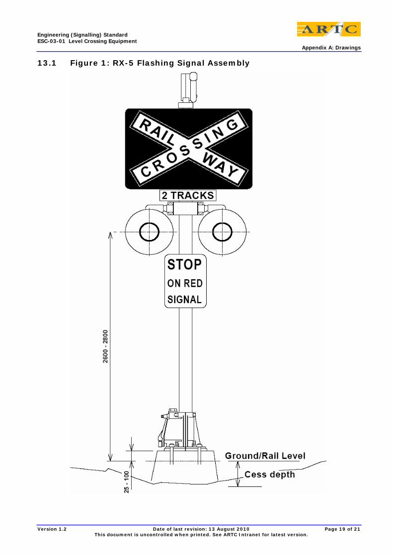
2.3 Light Unit Assemblies (RX5 Signal) Cross-arms assemblies shall be available in two light (uni-directional) and four light (bi-directional) form and generally conform to AREMA C&S Manual Part 3.2.50.
The cross-arm should preferably be made from a cast Aluminium Alloy which meets the requirements of AS 1874 for a medium strength, high corrosion resistant cast aluminium alloy. Alternatively, if fabricated, a medium strength, high corrosion resistant wrought aluminium alloy to AS 1734 may be used.
They shall be mounted on the cross-arm with approximately 760mm between centres and fitted to a pipe mast with lamp centres at a height of 2590mm above road level.
Version 1.2 Date of last revision: 13 August 2010 Page 8 of 21 This document is uncontrolled when printed. See ARTC Intranet for latest version.
Engineering (Signalling) Standard ESC-03-01 Level Crossing Equipment Road Level Crossings
Back to back mounting centres for four light assemblies shall be as shown in AREMA C&S Manual Part 3.2.50 for level crossing protection light installations.
Light units shall be fitted with hoods and backgrounds of the minimum size specified in AREMA C&S Manual Part 3.2.35.
The Active Advance Warning Assembly RX11 shall be in accordance with AS 1742.7 and the requirements of the Road Authority.
A RX-5 flashing light and boom assembly is shown in Appendix A, figures 1 and 2.
2.4 Audible Warning Devices
2.4.1 Bell
The level crossing bell shall generally comply with AREMA C&S Manual Part 3.2.60.
The bell shall be designed to mount directly on the top of the post and be provided with an adaptor, where required, to suit the diameter of the heavy steel tube used.
Nominal operating voltage shall be 10v DC and the bell shall operate to specification within the range 8 – 15 volts DC with a strike rate of 150 – 200 strikes per minute.
2.4.2 Electronic Device
The electronic audible alarm device shall be a volume adjustable audible warble alarm.
The alarm shall be mounted on a suitable corrosion protected steel or aluminium bracket fixed to the signal post and shall be enclosed in a lockable hinged cage. The top of the cage shall be solid covered to reduce the UV exposure of the alarm.
The nominal operating voltage of the audible alarm shall be 12v DC with an operating range of 8–18v DC.
2.5 Masts Masts and bases shall be hot dipped galvanized to AS 1650 after fabrication.
Where there is no bell mounted on top of the mast, galvanized sealing caps shall be provided.
Terminals used in bases and masts shall be at least 'Klippon SAK6' or equivalent.
2.5.1 Flashing Light Mast
For Flashing Light signals only installations the mast shall be a 100mm nominal bore heavy steel tube (114mm O.D) to AS 1074.
2.5.2 Boom Barrier Mast
For flashing lights and boom barrier installations the mast shall be a 125mm nominal bore heavy steel tube (140 mm O.D) to AS 1074.
2.5.3 Frangible Base
The cast base shall provide a frangible element in the post assembly to mitigate the damage to a road vehicle that may impact it.
Fully fabricated steel post base designs are not permitted, as they are not frangible.
2.6 Boom Barrier Mechanisms Mechanisms shall preferably be operated by an electric motor driving through a gearbox, with an effective low current hold – clear device, and shall generally comply with the requirements of AREMA C&S Manual Part 3.2.15.
Version 1.2 Date of last revision: 13 August 2010 Page 9 of 21 This document is uncontrolled when printed. See ARTC Intranet for latest version.
Engineering (Signalling) Standard ESC-03-01 Level Crossing Equipment Road Level Crossings
The boom mechanism shall meet the following requirements:
• Power down assist shall be provided between 90º and 50º
• Descent time:10 – 12 seconds
• Raise Time:
• With 9 volts at the motor 20 seconds
• With 16 volts at the motor 7 seconds
• Maximum current shall not exceed 15A at 9v for maximum length (approx 10 m) booms.
The circuit controller shall provide the following contacts for control and operation of the gate mechanism.
• Those required for control of the gate mechanism
• 85º - 90º for light control
• 90º - 10º for bell control
• 5º - 0º for gate down indication
Under failure conditions crossing entry booms shall free fall to the horizontal position and effective snubbing shall be provided.
Note: Exit booms in four quadrant applications shall rise under power failure conditions. See 3.2.3
2.7 Boom Barrier Arms Boom barrier arms shall be manufactured from Glass Reinforced Plastic (GRP) or from a combination of aluminium and GRP. If combination construction, the maximum nominal length of the aluminium section shall not exceed 4.8 metres.
The nominal length of a boom arm shall be measured from the centre line of the mast, on which the mechanism is mounted, to the tip of the boom arm.
The tip of the boom arm shall not extend beyond the centre line of the carriageway for undivided roads and not beyond the edge of the median strip on divided roads.
GRP or combination Aluminium / GRP boom arms may be fitted with breakaway mechanisms or shear pins or similar where attached to the gate arm support.
Boom arms shall be finished in engineering grade or high density retro-reflective red and white diagonal stripes complying with AREMA C&S Manual Part 3.2.25.
2.8 Boom Arm Lights Boom lights shall be visible to road traffic on both sides of the level crossing.
The light may take the form of a 360° red marine lantern suitably shielded from the train driver or a 75 – 100 mm diameter red double sided round light as described in the AREMA C&S Manual Part 3.2.40.
The number of boom lights for various lengths of boom shall be in accordance with AREMA C&S Manual Part 3.2.40 and as a minimum be three (3) with one (1) fixed at a point between 450mm and 150mm from the tip of the boom arm. The tip light shall display a steady red light when operated with the other two flashing alternately with the main flashing light signals.
Lamps shall be 10 volt 18 watt SC S11 single CC6 filament to AREMA C&S Manual.
LED light units provided shall be the same size and as a minimum, the same intensity of indication. In-built redundancy, operating voltage range and surge protection shall be as specified in Section 2.2.2.
Version 1.2 Date of last revision: 13 August 2010 Page 10 of 21 This document is uncontrolled when printed. See ARTC Intranet for latest version.
Engineering (Signalling) Standard ESC-03-01 Level Crossing Equipment Road Level Crossings
2.9 Signs and Road Markings
2.9.1 Constructor Supplied Items
The configurations of signs and their layout at level crossings shall comply with AS 1742.7 and AS 1743.
The Train Drivers Approach sign shall be installed such that there is one for each railway approach to the level crossing at the point at which the train initiates the level crossing warning equipment.
This signage shall be consistent with relevant addendums to the Code of Practice for the Defined Interstate Rail Network. Other Road Signs
2.9.2 Other Signage
All road side approach warning signs shall comply with AS 1742.7 and AS 1743 and any relevant Road Authority requirements.
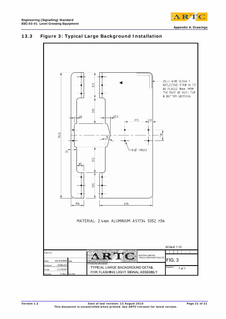
2.10 Enlarged Background When the road alignment is such that the sun will rise or set behind the level crossing signals when viewed from the road approaches, a large one piece background should be fitted to the light unit assembly. This background shall be additional to the standard backgrounds fitted to the light units. One only background is required per flashing light signal assembly.
The post and base mounting arrangements shall be appropriate for the additional wind loading of the enlarged background.
The enlarged background details are shown in Appendix A, figure 3.
2.11 Guard Rails Guard rails are not required for ARTC purposes.
In some States of Australia, the body vested with the care, control and management of the road concerned (Road Authority) require the provision of guard rails on protected level crossings. Where this is the case the Road Authority will arrange for the installation of guard rail/s. The Road Authority will be responsible for the maintenance of the Guard Rails.
The Constructor shall liaise with the Road Authority and if required position the Flashing Light and /or boom arm mechanism foundations such that the guard rail/s can be accommodated.
2.12 Foundation Flashing Light and Boom arm mechanism foundations can be either poured in situ or pre-cast concrete foundation type assembly.
The foundation shall be of sufficient size, shape and depth in ground to support fully dressed masts in wind speeds up to 160 kph with concrete strength at 28 days being not less than 20 MPa.
The centre of the foundation should be 3.5 metres from the running face of the nearest rail and minimum 2.5 metres from the edge of the sealed pavement or roadside curbing/gutter.
The top of the concrete foundation should be level with the road pavement level or, where curbing / gutters are provided no more than 75mm above the top of the curbing/gutters.
Holding down bolts in foundations shall be 24 mm hot dip galvanised steel and shall be fitted with galvanised flat washers, nuts and locknuts.
Masts shall be installed and levelled so that the signal mast is vertical.
Upon completion of the levelling, the mast base shall be grouted with low shrinkage concrete grout and all loose packers removed.
Version 1.2 Date of last revision: 13 August 2010 Page 11 of 21 This document is uncontrolled when printed. See ARTC Intranet for latest version.
Engineering (Signalling) Standard ESC-03-01 Level Crossing Equipment Pedestrian Crossings
3 Pedestrian Crossings
3.1 Pedestrian Light Units Light Units for crossings whether fitted with lights only or with swing gates or booms shall be symbolic indications such as a flashing “Red Man” to AS 2144. Unless otherwise specified, there shall be two lights on each side of the crossing, one light facing oncoming pedestrians and one light facing across the railway tracks.
“Red Man” lights shall be LED illuminated with the LED assemblies configured for either nominal 12v DC (8 – 18 v DC) or 110volt (90 – 130v) AC operation depending on the power supply at the pedestrian crossing.
In Queensland a “Green Man” (Walk) symbol shall be displayed when the “Red Man” is extinguished
Open circuit failure of a single LED shall not result in more than 33% loss of indication and the indicated symbol shall remain identifiable.
3.2 Pedestrian Gate Mechanisms
3.2.1 General
Swing gate mechanisms are the preferred method of providing protection at pedestrian level crossings where protection additional to the “Red Man” lights is required.
Pedestrian boom gate arrangements shall only be used where there is insufficient clearance between the access way and the railway line to permit a swing gate to be used. Pedestrian booms shall be driven from an approved mechanism.
3.2.2 Swing Gate Mechanism
The swing gate mechanism shall be capable of operating swing gates up to 1.5 metres in width. Nominal operating voltages shall be 12v (8 – 16v) DC or 110v (90 – 130v) 50 Hz AC. The mechanism shall be capable of:
• Closing the gate (through 90°) in 8 seconds or less.
• Tolerating the gate being restrained part way through its arc for an indefinite period without detriment to the motor or mechanism.
• Resuming movement in the intended direction when restraint is removed.
• Tolerating being forced from the closed or open position without detriment to motor or mechanism.
• Returning to the correct position when the force is removed.
Swing gates shall be of welded metal construction of sufficient strength so as not to distort or sag with a vertical load of 150 kg applied at the tip of the gate.
The gate shall not twist if restrained at top or bottom with a load of 150 kg applied at the tip of the gate opposite the pivot and opposite the restraint.
They shall be non climbable and similar in construction to swimming pool access gates. Gate supports shall not bend, twist or distort with similar loads applied or with a load of 250 kg applied to the top of the gate support in any direction.
The entire gate shall be hot dipped galvanized to AS1650 after fabrication.
3.2.3 Boom Gate Mechanism
The boom mechanism shall preferably be electric motor driven and capable of operating booms up to 3.0 metres in length. Nominal operating voltages shall be 12v (8 - 16v) DC or 110v (90 - 130v) 50 Hz AC. The maximum current for 12v DC mechanisms shall not exceed 8 Amps.
Version 1.2 Date of last revision: 13 August 2010 Page 12 of 21 This document is uncontrolled when printed. See ARTC Intranet for latest version.
Engineering (Signalling) Standard ESC-03-01 Level Crossing Equipment Pedestrian Crossings
The mechanism shall be gravity drop for entry booms (no power down assist) and shall be counterweighted and/or snubbed to provide a drop time from 90° to horizontal of 6 to 8 seconds with the time from 90° to 50° not less than 2.5 seconds.
Note: For exit booms in four quadrant applications the boom mechanism shall provide for gravity rising under the influence of the counter weights.
The mechanism and counter-weighting shall be arranged so that there is no possibility of the boom failing to drop (or rise as required) under any wind condition likely to be encountered in the location where it is installed.
The hold clear system within the mechanism shall not draw current in excess of 500 mA when in the hold position.
Boom gate arms shall be made from GRP, Aluminium or combination GRP/Aluminium. No lighting is required on the boom gate arm.
Boom gate arms shall be of sufficient length to permit the mechanism to be placed clear to one side of the pathway and to overlap the other side of the pathway (generally through a slot in the fence) by at least 100mm when in the horizontal position.
Boom gate arms shall be finished in gloss white.
3.3 Audible Warning Device The audible alarm shall be as indicated in Sections 2.4.1 and 2.4.2. Unless otherwise specified one alarm shall be fitted to each side of the crossing, facing oncoming pedestrians. The audible alarm can be turned off, in built-up areas, when the booms are fully lowered and/or Pedestrian gates are closed.
3.4 Pedestrian Masts The mast shall be 100mm nominal bore heavy tube to AS 1074 and be hot dipped galvanized after fabrication.
The mast shall be protected against corrosion to achieve the required life span of 20 years without the need to renew the protective coating.
3.5 Foundations The foundations for both Swing Gates and Boom Gates shall be of sufficient size, shape and depth in ground to support fully dressed masts in wind speeds up to 160 kph with concrete strength at 28 days being not less than 28 MPa.
The top of the concrete foundation should be 150 mm above the road pavement level or, where curbing/gutters are provided, 75 mm above the top of the curbing/gutter.
Holding down bolts in foundations shall be 12 mm hot dip galvanised steel and shall be fitted with galvanised flat washers, nuts and locknuts.
Masts shall be installed and levelled so that the signal mast is vertical.
Upon completion of the levelling, the mast base shall be grouted with low shrinkage concrete grout and all loose packers removed.
3.6 Signs The signs to be displayed at pedestrian crossings shall be in accordance with AS 1742.7. They shall be displayed on either side of the crossing in a position where they can be best viewed by approaching pedestrians.
3.7 Pedestrian Access The pedestrian access and protection includes the pathway, tactile tiles where appropriate and pedestrian mazes. Fencing may also be applicable for these.
Version 1.2 Date of last revision: 13 August 2010 Page 13 of 21 This document is uncontrolled when printed. See ARTC Intranet for latest version.
Engineering (Signalling) Standard ESC-03-01 Level Crossing Equipment Control Equipment
3.8 Fencing Fencing for gated and maze crossings shall be 1.5m high weld mesh. Note that non standard corral fencing may be considered in some circumstances such as heritage sensitive areas, on application to the ARTC Infrastructure Manger. Fencing leading up to a crossing corral (gated or maze) shall not be less than 1.0m in height and where associated with existing station platform fencing, should match that fencing. Note that boundary fencing should not be less than 1.8m in height.
4 Control Equipment
4.1 Control of Lights/Booms/Gates Equipment used to control the operation of Road and Pedestrian crossings shall have the same safety and reliability characteristics as that required for railway signalling systems and equipment, and be approved for use on the ARTC network. The controls provided must be constructed strictly in accordance with the approved design.
4.2 Flasher Units Duplicated electronic flasher units shall be provided. Westinghouse “SafeFlash” type or “Ironcore” static flashers are acceptable. The wiring to each highway signal shall be such that the failure of one flasher or the open circuit failure of one wire or connection point shall not result in the total loss of all the highway signals on one side of the level crossing and generally be in accordance with AREMA C&S Manual Part 3.1.10.
The “flash rate” for these units should be variable within the range of 40 to 50 flashes per minute and adjusted to the appropriate States requirements All flasher units used must be type approved and their application be in accordance with the approved design.
4.3 Level Crossing Predictors The level crossing predictor housing is to be located as close as possible to the intended feed point of the level crossing predictor.
The housing of level crossing predictors must be arranged so that the maximum internal temperature of the housing is 70oC for the full range of environmental temperatures likely to be experienced at the location.
Surge protection shall be provided in accordance with ARTC specification SCP 04 Lightning and Surge Protection Requirements for Electronic equipment subject to Category C exposure.
The power supply for the operation of level crossing predictors must be a float charged battery arrangement with a battery of a least 10AH capacity directly connected to the power input terminals regardless of the reliability of the supply from which it is powered.
In the case where the level crossing predictor drives flashing lights and other warning equipment the power supply may be obtained from a battery backed up source provided for this purpose.
4.4 Equipment Boxes The equipment box or hut used must be in accordance with ARTC standards and be suitable for the environmental temperatures likely to be encountered. The environmental temperature requirements should take into account a maximum environmental temperature of 50oc unless the Infrastructure Manger advises that a lower temperature may be used. The heat load of the apparatus must be carefully considered so that the temperature ratings of any equipment within the equipment box is not exceeded under normal operating conditions with the maximum environmental temperature or equipment is to be appropriately de rated.
Version 1.2 Date of last revision: 13 August 2010 Page 14 of 21 This document is uncontrolled when printed. See ARTC Intranet for latest version.
Engineering (Signalling) Standard ESC-03-01 Level Crossing Equipment Power Supply
5 Power Supply
5.1 Mains Power Where mains supply to the crossing is required by the design it shall be 240volt single phase supply derived from the Supply Authority. The installation of the power feed shall be in accordance with AS 3000 and any local applicable electrical regulations.
A 240 volt distribution board located within the equipment housings shall provide separate circuits for hut lighting and power circuits with each device being individually protected.
5.2 DC Power Supplies A 12 volt and/or 18 volt DC supply shall be provided in accordance with the design. Care shall be taken with the installation to ensure that the correct wire sizes are used and where loop feeds are provided these are implemented so that the failure of one fuse or link does not disable the supply.
Where Predictors, LX Monitors or other electronic level crossing equipment are used, then the maximum and minimum voltage ranges shall be suitable for the equipment.
5.3 Batteries Batteries shall be the type and be mounted in the location specified in the design. In the case of wet cells these must be mounted in separate enclosure to prevent corrosion from electrolyte fumes. Wet cells should be located on a wooden or non corroding plinth to prevent corrosion to the enclosed floor.
The batteries shall have sufficient capacity to operate the active level crossing protection equipment, associated control equipment, train detection equipment and any railway signalling fed from the level crossing location for a minimum period of 48 hrs (2 days) with 10% residual capacity under average rail traffic densities.
The capacity of the level crossing battery under normal power supply failure conditions is critical to the safe operation of the level crossing. The Contractor shall provide Design calculations to fully substantiate this battery capacity requirement.
The 12volt DC (nominal) flashing light battery shall be a low maintenance long life stationary type sealed Lead Acid 140AH @ 100Hr capacity.
As a preference sealed long life cells should be used wherever possible
5.4 Battery Chargers Battery chargers shall be type approved and generally 240 volts AC-50 Hz single phase units giving a regulated output suitable for maintaining the battery / batteries in a fully charged state. They should be matched to the battery technology in use. The type of battery charger used may be influenced by maintenance replacement considerations; the infrastructure manager will advise if this is the case.
5.5 Solar Power Where solar power is used, the batteries and solar panels shall be sized to cover the requirements for the specific location. The solar panels shall be protected against vandalism and theft. The glass of the solar panels shall be etched with “Property of ARTC” or “Stolen from ARTC”.
Version 1.2 Date of last revision: 13 August 2010 Page 15 of 21 This document is uncontrolled when printed. See ARTC Intranet for latest version.
Engineering (Signalling) Standard ESC-03-01 Level Crossing Equipment Cables and Wiring
6 Cables and Wiring The Termination of these cables and wiring shall be in accordance with ESC-07-03 Installation of Equipment Racks & Termination of Cables and Wiring.
The 120 Volt lead from the battery charger shall comply with AS 3191. Location power and lighting wiring shall comply with AS 3000.
Special attention shall be paid to the use of the correct connection technique for track circuit leads appropriate to the type of level crossing control equipment used.
7 Lightning and Surge Protection Lightning and surge protection shall be provided in accordance with the requirements of ESC-09-02 Lightning and Surge Protection Requirements.
8 Level Crossing Housing Equipment for the control and operation of the level crossing shall be housed in a prefabricated sandwich panel walk-in location or alternatively in aluminium or stainless steel location cases, complying with ESC-07-03 Small Buildings, Location, Terminal and General Purpose Cases.
This installation shall be located not less than 15 metres from the edge of the roadway and as close to the railway boundary as practical to reduce exposure in the event of an accident and to reduce obstruction to the line of sight of an approaching train.
The level crossing location shall be provided with an identification plate as defined in Section 11.
The test, emergency and manual operation boxes together with a weatherproof, vandal resistant telephone shall be mounted on the outside of this location usually on the side facing the railway line. Alternatively, these may be mounted within the emergency operation traffic hut located adjacent to the level crossing, where such a hut is provided.
Where the Manual Operation Box would not be in a convenient position for an operator, it may be located close to the level crossing.
Wherever possible there shall be provision made at the level crossing for a maintainer’s vehicle to be parked off road, near the equipment housing.
9 Test/Emergency/Manual Box A suitable box or boxes shall be provided to house the switches for Test Operation, Emergency Operation and Manual Operation of the Level Crossing.
For associated road and pedestrian crossings, common test and emergency boxes shall operate both.
The test box shall be mounted on the external side wall of the level crossing location and be secured with the nominated padlocks for the particular rail corridor.
It shall be assembled and wired as detailed in the signalling design.
10 Telephones Generally there is no requirement for the provision of a telephone at level crossing installations.
Communication requirements for maintenance staff should preferably be achieved by mobile telephone provided coverage is suitable.
A sign shall be provided that clearly displays sufficient information so that the general public and rail infrastructure workers can report any issues related to the level crossing installation and/or its operation, and includes:
• Level Crossing Identification Number
Version 1.2 Date of last revision: 13 August 2010 Page 16 of 21 This document is uncontrolled when printed. See ARTC Intranet for latest version.
Engineering (Signalling) Standard ESC-03-01 Level Crossing Equipment Monitor
• Contact telephone number
• Level crossing location name and
• Kilometrage
The sign shall be mounted on the roadway side of the level crossing location or alternatively be positioned such that there is clear visibility to vehicular and pedestrian users of the level crossing.
11 Monitor The level crossing monitor, monitors the status of a level crossing, logs events, reports warning or failure conditions to a central location, and provides facilities to remotely test the level crossing battery supply.
Each level crossing with active protection shall be fitted with a status monitoring system which is capable of performing tests on specified functions on command and provide indications of faults and warnings to remote control / monitoring location.
The monitoring system shall be in accordance with “Level Crossing Monitor” (Spec. No. TBA) and shall provide data that is acceptable as legal evidence in the event of an enquiry following a level crossing fatality, accident or failure condition incident and be currently type approved for use on the ARTC network.
Details of crossing protection operation shall be recorded and retained in the monitor log for a minimum period of 7 days or downloaded to the remote control/monitoring location at intervals which will preclude overwriting of the monitor log.
All stored data shall be accessible for interrogation or download at any time, via dial-up modem, from remote locations.
Any other requirements will be as specified by the Signal Design and/or nominated in the Particular Specification.
12 Track Conditions The Constructor shall ensure that the track condition is appropriate for the design in respect of:
• Rail head condition
• Ballast resistance
• Welded or Mechanically jointed track
• Insulated Steel Sleepers
If there is any doubt, the situation should be brought to the attention of the ARTC representative for resolution.
Version 1.2 Date of last revision: 13 August 2010 Page 17 of 21 This document is uncontrolled when printed. See ARTC Intranet for latest version.
Engineering (Signalling) Standard ESC-03-01 Level Crossing Equipment Appendix A: Drawings
13 Appendix A: Drawings Figure 1: RX-5 Flashing Signal Assembly
Figure 2: RX-5 Flashing Signal Assembly with Boom
Figure 3: Typical Large Background Details
Version 1.2 Date of last revision: 13 August 2010 Page 18 of 21 This document is uncontrolled when printed. See ARTC Intranet for latest version.
Engineering (Signalling) Standard ESC-03-01 Level Crossing Equipment Appendix A: Drawings
13.1 Figure 1: RX-5 Flashing Signal Assembly
Version 1.2 Date of last revision: 13 August 2010 Page 19 of 21 This document is uncontrolled when printed. See ARTC Intranet for latest version.
Engineering (Signalling) Standard ESC-03-01 Level Crossing Equipment Appendix A: Drawings
13.2 Figure 2: RX-5 Flashing Signal Assembly with Boom
Version 1.2 Date of last revision: 13 August 2010 Page 20 of 21 This document is uncontrolled when printed. See ARTC Intranet for latest version.
Engineering (Signalling) Standard ESC-03-01 Level Crossing Equipment Appendix A: Drawings
13.3 Figure 3: Typical Large Background Installation
Version 1.2 Date of last revision: 13 August 2010 Page 21 of 21 This document is uncontrolled when printed. See ARTC Intranet for latest version.