• ASME Section IX and AWS qualified welding system
• Designed to ASME B31.1 and B31.3 guidelines
• Hermetically sealed switching mechanisms available
• Stainless steel switching mechanisms
• High-temperature capability (up to 1200 °F)
• Wide variety of explosion-proof housings
• Versatile switching mechanisms which retro-fit into other manufacturers’ units
SOR® mechanical level switchesare rugged, industrial products specifically designed for versatility of application. This catalog contains application and ordering data for float and displacer-operated level switches. Switches are available with flanged or sealed chambers or as insertion models.
Options available for each type of switch include: switch type and number, housing type, chamber material, process connections, accessories, and more. Units may be customized to suit customers’ needs.
Inside this catalog you will find solutions to your level sensing puzzles. SOR mechanical level switches have many configurations available. If you don’t see what you need, we will engineer a custom solution for your application.
200 Series
700 Series
• Worldwide listings and certifications
• Quick worldwide delivery
• ASTM grade materials with certified mill test reports used
• EAC Certificate for Russia
• Safety Certified to IEC 61508 (SIL) SOR products are certified to IEC
61508 for non-redundant use in SIL1 and SIL2 Safety Instrumented Systems for most models. For more details or values applicable to a specific product, see the Safety
Standard Chamber Materials all SOR level switch chambers are constructed using aSTm grade materials with full material certification. mill Test Reports are kept on file for all raw materials. Copies are available upon request at the time of order placement.
Carbon Steel Construction Chamber Center Section ..........................................a106 Grade B Flanges/Weld Fittings ..................................................................a105 Weld Cap ............................................................................ a234-WPB Studs/Nuts ............................................................ a193-B7/a194-2H
Stainless Steel Construction Chamber Center Section .................................. a312-TP316/316L Flanges/Weld Fittings ..............................................a182-316/316L Weld Cap ....................................................................a403-316/316L Studs/Nuts ............................................................ a193-B7/a194-2H
Quality Assurance SOR maintains a high level of quality throughout our corporation. many quality assurance featuresare built into our products.
§ ISO 9001 certified engineering design and production system (certified since 1993).§ Level-welded chambers designed to the guidelines of aSme B31.1 and B31.3 (inspection certificate available – see page 29).§ all welders and weld procedures are qualified and maintained to aSme Section IX.§ all aSTm grade materials used - Certified mill Test Reports required on all raw materials.
Switching Mechanisms SOR switching mechanisms are designed for use in punishing industrial conditions.
§ all stainless steel construction - no aluminum or brass.§ Temperature ratings available from -65°F (–54°C) to 1000°F (538°C) on dry, non–condensing
services.§ Condensing service (steam) temperature ratings available up to 800°F (427°C), and up to
1200°F (649°C) with protection (see page 26).§ available switching mechanisms include hermetically sealed, standard open contacts, or
pneumatic contacts.§ agency listings are available on most switch mechanisms: UL, CSa, aTeX or IeCex.
Gaskets§ all standard models are provided with a Nitrile binder composite gasket that is selected for its
resistance to hydrocarbons and steam. § For high-temperature, high-pressure or NaCe-constructed units, a spiral-wound gasket is used
with 316SS wound-around Grafoil. § extreme high-pressure model 802 uses a soft-iron, ring-joint gasket on the chamber head flange.
Internal Trim§ all sensing elements (floats and displacers) are constructed of either 316/316LSS or porcelain
as a minimum. § attraction sleeves are available in 400SS as a standard, with 316/316LSS or other exotic
metals as an option. § all other wetted internal parts are 316SS or better. Displacer springs are made of Inconel 600.
Product Support SOR has a full-time engineering staff dedicated to solving your mechanical level switch problems.
engineers and technicians are knowledgeable about sales and production techniques, and arededicated to providing the best solution to our customers at the best price.
Float-Operated Level Switches - VerticalModel Series 100, 200 and 300
The float rides on the process liquid surface, precisely tracking liquid surface motion.
Rising liquid level lifts the float, sliding the attraction sleeve up inside the enclosing tube and into the magnetic field to actuate the electrical or pneumatic switch (signaling liquid presence).
Subsequently, falling liquid level lowers the float, drawing the attraction sleeve out of the magnetic field to deactuate the electrical or pneumatic switch (signaling liquid absence). Float-type level switches are generally able to handle high-temperature applications, and sometimes prove useful for close interface detection.
Floats can operate up to two switching elements. Independent switching levels may be obtained with tandem floats. Consult the factory for special float-switching arrangements.
Principles of Operation
Float-Operated Level Switches - HorizontalModel Series 108/208 and 400The float rides on the process liquid surface, precisely tracking liquid surface motion.
Rising liquid level lifts the float via a pivot mechanism, sliding the attraction sleeve down inside the enclosing tube and out of the magnetic field to deactuate the electrical or pneumatic switch (signaling liquid presence).
Subsequently, falling liquid level lowers the float, drawing the attraction sleeve into the magnetic field to actuate the electrical or pneumatic switch (signaling liquid absence). Float-type level switches are generally able to handle high-temperature applications.
Displacer controls offer alternative features to the float-operated control. The sensor is a weight (displacer), heavier than the liquid, that is suspended by a spring. When liquid contacts the displacer, a buoyancy force is produced, which causes the effective weight of the displacer to change. This causes the spring to retract slightly to a new equilibrium position. When the spring retracts, the attraction sleeve also moves upward into the field of the external magnet, thus overcoming the force of the bias spring and actuating the switching element.
This principle provides for narrow or wide switching differential, and allows switching point alteration by moving the displacer(s) up or down the suspension cables.
Displacers may be arranged in combinations of narrow and wide differential to operate up to three switching stages. Displacer controls operate under higher pressure conditions than float-operated switches.
Displacer-Operated Level Switches Model Series 700, 730, 740, 750 and 800
How to OrderBelow is the SOR quick select model number tree that provides you with options to configure and order a product for your application. •Youmustselectadesignator for each component (see corresponding pages) •Referencetables,chartsandadditionalinformationareprovidedthroughoutthecatalogto
help you make your selections.
Carbon Steel316/316L Stainless Steel
See Page 14 for more information
See Pages 15-17 for selection information
316/316L SS Float/Displacer material 400 SS attraction Sleeve 316/316L SS Float/Displacer material & attraction Sleeve monel 400 Float/Displacer material & attraction Sleeve 321 SS Float material400 SS attraction Sleeve 321 SS Float/Displacer material316/316L SS attraction Sleeve Porcelain Displacer material400 SS attraction Sleeve Porcelain Displacer material 316/316L SS attraction Sleeve See Page 18 for more selection information
See Pages 19-21 for selection information
See Page 22 for selection information
See Page 23-25 for selection informationmultiple accessories can be selected
See Pages 7-13 for selection information
model Selection is broken into
two steps: 1a & 1b
First, determine which model series is needed.
Then, go to the associated page to select the model
§ Indirect mount is required because tank cannot be easily shutdown for service § When turbulence is high enough to cause false readings/damage to the displacer§ Flanged service connection for maintenance, cleaning, or troubleshooting
740, 804
Sealed Non-Serviceable
external Chamber Displacer
Switch (p. 11)
§ Indirect mount is required because tank cannot be easily shutdown for service § When turbulence is high enough to cause false readings/damage to the displacer§ The chamber is welded to prevent tampering and is lower cost
700 Series
Single-Stage Top Insertion
mount Displacer Switch (p. 12)
§ Used for high alarm or level control through adjustable wide differential option§ Direct tank mount
730
Dual-Stage Top Insertion
mount Displacer Switch (p. 12)
§ Used for high-high, high-low, and low-low level alarms§ Direct tank mount
750
Triple-Stage Top Insertion
mount Displacer Switch (p. 13)
§ Three switching points to provide numerous combinations of ways to configure the point level switch outputs§ Direct tank mount
Level Switches
The first step to creating your model number is to determine whether a float or a displacer-based level switch is needed. See below for the different options for selecting the right technology for a specific application.
Model Series Application
100 Series
Flanged Serviceable
external Chamber
Float Switch (p. 8)
§ Indirect mount is required because tank cannot be easily shutdown for service § When turbulence is high enough to cause false readings/damage to the float§ Flanged service connection for maintenance, cleaning, or troubleshooting
200 Series
Sealed Non-Serviceable
external Chamber
Float Switch (p. 9)
§ Indirect mount is required because tank cannot be easily shutdown for service § When turbulence is high enough to cause false readings/damage to the float§ The chamber is welded to prevent tampering and is lower cost
108, 208Steam
Condensate external
Chamber Float Switch
(p. 9)
§ Horizontal float switch designed specifically to handle high temperature/pressure § Low SG capabilities§ Steam applications§ Serviceable/Non-serviceable options
300 Series
Top Insertion mount Float
Switch (p. 10)
§ Quick and easy installation; direct mount§ Low Cost Solution§ Used for high level alarm/overfill protection
400 Series
Side Insertion mount Float
Switch (p. 10)
§ Quick and easy installation; direct mount§ Used for specific point level indication§ Can be installed at any height of the tank
Float Selection Float switches are inherently less expensive as they have a very simple operating mechanism compared to displacer technology. Because of this, they can operate extremely well in high temperature applications. The performance and functionality of a float switch are unaffected by changes in process conditions such as temperature, pressure, and dielectric properties. Floats however have limited pressure and SG capabilities compared to displacer technologies.
Step 1a: Model Selection FLOAT or DISPLACER
316/316L SS Float/Displacer material 400 SS attraction Sleeve 316/316L SS Float/Displacer material & attraction Sleeve monel 400 Float/Displacer material & attraction Sleeve 321 SS Float material400 SS attraction Sleeve 321 SS Float/Displacer material316/316L SS attraction Sleeve Porcelain Displacer material400 SS attraction Sleeve Porcelain Displacer material 316/316L SS attraction Sleeve See Page 18 for more selection information
1amodel
numberbuilderSTEP
Displacer SelectionDisplacer based type level switches have high pressure capabilities and can be used for level control and interface detection. Because it operates as a force balance, displacers can achieve lower SG capabilities than float based technologies. Displacer technologies are limited by temperature as the higher temperatures change the properties of the spring used as a counterforce of the displacer.
*Consult the factory for pressure ratings and minimum SG of units with monel trim.
Using selected model, refer to the charts on pages 8-13 to match required pressure rating and specific gravity, based on design temperature. Once model number has been selected, go to page 14 for Step 2.
100 Series Float operated with a flanged, serviceable external chamber.
Maximum Working Pressure See page 27 for higher temperatures.
Single SwitchNote: Dual Switch, anti-vibration, pneumatic or extra-high temperature in ()
Standard w/ ET or FE Option
316SS / 400SS “B” Trim All 316SS “C” Trim 316SS / 400SS “B” Trim All 316SS “C” Trim
201202203
0.38 (0.44)0.52 (0.63)0.61 (0.72)
0.40 (0.46)0.55 (0.67)0.65 (0.76)
0.40 (0.44)0.55 (0.66)0.64 (0.75)
0.42 (0.48)0.59 (0.70)0.68 (0.79)
204205206
0.910.50 (0.56)0.65 (0.75)
0.960.52 (0.58)0.68 (0.79)
0.980.52 (0.58)0.68 (0.79)
1.030.54 (0.60)0.71 (0.82)
207209221
0.61 (0.67) 0.38 (0.41)0.64 (0.86)
0.63 (0.69)0.39 (0.42)0.72 (0.93)
0.63 (0.69)0.39 (0.42)0.71 (0.92)
0.65 (0.71)0.40 (0.43)0.78 (0.99)
*Consult the factory for pressure ratings and minimum SG of units with monel trim.
Level Switches 108 a-e1a-F-a1-N4-CRTT
108/208 Float operated, horizontal mounted switches with sealed, tamper-proof or flanged, serviceable chambers. See page 27 for pressure ratings at higher temperatures. Maximum Working Pressure
Minimum Specific Gravity For all model series 108/208, single switch only is equal to .65.Consult the factory for units used with specific gravity lower than .65.
1bmodel
numberbuilderSTEP
Step 1b: Model Selection Pressure Rating & Specific Gravity
Single SwitchNote: Dual Switch, anti-vibration, pneumatic or extra-high temperature in ()
316SS/400SS Trim (B) All 316SS Trim (C) All Monel Trim (M)
3012448
.40 (.45)
.44 (.49).42 (.48).46 (.52)
.48 (.54)
.53 (.59)
3032448
.68 (.79)
.75 (.87).72 (.84).80 (.91)
.82 (.93).91 (1.02)
3042448
.52 (.58)
.56 (.62).55 (.61).59 (.65)
.62 (.68)
.67 (.73)* Consult the factory for pressure ratings and minimum SG of units with monel trim.** Insertion depth is defined as the approximate value of a rising level setpoint at a Specific Gravity of 1.0. If more precise setpoint action is required, please select the SC option from the accessories section of the catalog. Note: an insertion depth or SC information must be supplied at the time of order on all 300 series switches.
Level Switches
Minimum Specific GravityModel Single Switch
401 .50
402 .90
403 .50
404 .60
405 .60
406 .60
400 Series Float-operated and suitable for horizontal-insertion mounting.
*Consult the factory for pressure ratings of units with monel trim. Standard displacer units are not available above 450°F (232°C).For higher temperatures up to 650°F (343°C), a special high temperature spring is available.Minimum Specific Gravity
Model Standard Switch
Anti-Vibration or Pneumatic Switch
741
0.43 0.57742
743
802 0.41 0.5
Level Switches
Minimum Specific Gravity
Model Standard Switch
Anti-Vibration or Pneumatic Switch
740 0.43 0.57
804 0.41 0.50
740 and 804 Displacer-operated with sealed, tamper-proof external chambers.
* Consult the factory for pressure ratings of units with monel trim. Standard displacer units are not available over 450oF (232oC).For higher temperatures up to 650°F (343°C), a special high temperature spring is available.
108 a-e1a-F-a1-N4-CRTT
1bmodel
numberbuilderSTEP
Step 1b: Model SelectionPressure Rating & Specific Gravity
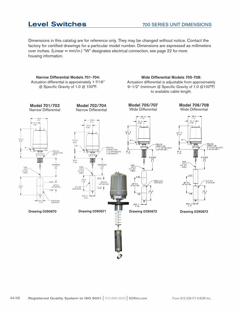
700 Series Single-stage, displacer-operated and suitable for top-insertion tank mounting.Maximum Working Pressure
ModelMinimum Specific
Gravity1 2 3Function Connection
StyleDisplacer Material
Connection Material
Pressure Rating - psi (bar)
100°F (38°C) 450°F (232°C)4
701 0.48
Narrow Differential
NPTPorcelain all 1000 (69) 750 (52)
702 0.43 SS all 1000 (69) 750 (52)
703 0.48 Flange Porcelaina105 285 (20) 185 (13)
316SS 275 (19) 182 (13)
704 0.43 Flange SSa105 285 (20) 185 (13)
316SS 275 (19) 182 (13)
705 0.32
Wide Differential
NPTPorcelain all 1000 (69) 750 (52)
706 0.29 SS all 1000 (69) 750 (52)
707 0.32 Flange Porcelaina105 285 (20) 185 (13)
316SS 275 (20) 182 (13)
708 0.29 Flange SSa105 285 (20) 185 (13)
316SS 275 (19) 182 (13)Notes: 1. an operating specific gravity is required for all 705 through 708 models at time of order. 2. minimum SG based on standard sized displacers and units without anti-vibration, pneumatic or extra high temperature switches. 3. For SS displacers, lower SG’s may be achieved using non-standard sized sensors. 4. Standard displacer units are not available over 450oF (232oC). For higher temperatures up to 650°F (343°C), a special high temperature spring is available.
730 Series Dual-stage, displacer-operated and suitable for top-insertion tank mounting.Maximum Working Pressure
ModelMinimum Specific Gravity123
Function Connection Style
Displacer Material
Connection Material
Pressure Rating - psi (bar)
100°F (38°C) 450°F (232°C)4
730 0.64
Narrow Differential
NPTPorcelain all 1000 (69) 750 (52)
731 0.57 SS all 1000 (69) 750 (52)
732 0.64 Flange Porcelaina105 285 (20) 185 (13)
316SS 275 (19) 182 (13)
733 0.57 Flange SSa105 285 (20) 185 (13)
316SS 275 (19) 182 (13)
734 0.55
Wide Differential
NPTPorcelain all 1000 (69) 750 (52)
735 0.49 SS all 1000 (69) 750 (52)
736 .055 Flange Porcelaina105 285 (20) 185 (13)
316SS 275 (20) 182 (13)
737 0.49 Flange SSa105 285 (20) 185 (13)
316SS 275 (19) 182 (13)Notes: 1. an operating specific gravity is required for all 730 models at time of order. 2. minimum SG based on standard sized displacers and units without anti-vibration, pneumatic or extra high temperature switches. 3. For SS displacers, lower SG’s may be achieved using non-standard sized sensors. 4. Standard displacer units are not available over 450oF (232oC). For higher temperatures up to 650°F (343°C), a special high temperature spring is available.
108 a-e1a-F-a1-N4-CRTT
1bmodel
numberbuilderSTEP
Step 1b: Model Selection Pressure Rating & Specific Gravity
750 Series Three-stage, displacer-operated and suitable for top-insertion tank mounting.Maximum Working Pressure
ModelMinimum Specific
Gravity1 2 3 Function Connection
StyleDisplacer Material
Connection Material
Pressure Rating - psi (bar)
100°F (38°C) 450°F (232°C)4
750 0.80
Narrow Differential
NPTPorcelain all 1000 (69) 750 (52)
751 0.71 SS all 1000 (69) 750 (52)
752 0.80 Flange Porcelaina105 285 (20) 185 (13)
316SS 275 (19) 182 (13)
753 0.71 Flange SSa105 285 (20) 185 (13)
316SS 275 (19) 182 (13)
754 0.85
Wide Differential
NPTPorcelain all 1000 (69) 750 (52)
755 0.81 SS all 1000 (69) 750 (52)
756 0.85 Flange Porcelaina105 285 (20) 185 (13)
316SS 275 (20) 182 (13)
757 0.81 Flange SSa105 285 (20) 185 (13)
316SS 275 (19) 182 (13)Notes: 1. an operating specific gravity is required for all 750 models at time of order. 2. minimum SG based on standard sized displacers and units without anti-vibration, pneumatic or extra high temperature switches. 3. For SS displacers, lower SG’s may be achieved using non-standard sized sensors. 4. Standard displacer units are not available over 450oF (232oC). For higher temperatures up to 650°F (343°C), a special high temperature spring is available.
Level Switches 108 a-e1a-F-a1-N4-CRTT
1bmodel
numberbuilderSTEP
Step 1b: Model SelectionPressure Rating & Specific Gravity
Select chamber process connection material from the following chart. maximum working pressure shown in the charts in Step 1b is based on the material selected here. Alternate materials can be provided, please consult the factory.
Step 2: Chamber/Process Connection Material
Model Material Designator
all models
Carbon Steel a
316/316L Stainless Steel C
Note: Chambered models supplied with a105 and a234-WPB fittings for Carbon steel and a182-316/316L and a403-316/316L fittings for Stainless Steel configurations.
Select a process connection, size, style and rating from the charts below. Consult the factory for variations. Flanged process connections may reduce the maximum working pressure of the unit.
100 and 200 Series See page 33-36 for dimensions.
Model Style Size
Connection Designator
Standard Flange
NPT Thread
Socket Weld 150# 300# 600#
100 Series
200 Series
VH
1”
a1a a1B a1C a1D a1e
VV - - B1C B1D B1e
VVD C1a C1B C1C C1D C1e
VVT - - D1C D1D D1e
VH
1-1/2”
a5a a5B a5C a5D a5e
VV - - B5C B5D B5e
VVD C5a C5B C5C C5D C5e
VVT - - D5C D5D D5e
VH
2”
a2a* a2B* a2C a2D a2e
VV - - B2C B2D B2e
VVD C2a* C2B* C2C C2D C2e
VVT - - D2C D2D D2e*Not available on models 121, 122, 221.
108 and 208 Series See page 37 for dimensions.
Model Size Style ConnectionDesignator
108208
1”NPT e1a
Socket Weld e1B
1-1/2”NPT e5a
Socket Weld e5B
2”NPT e2a
Socket Weld e2BNPT connections not recommended above 900°F.
300 Series See page 38 for dimensions.
Model Size
Connection Designator
Standard Flange
NPT Thread 150# 300# 600#
300 Series
1” F1a - - -
2” F2a - - -
3” F3a F3C F3D F3e
4” - F4C F4D F4e
6” - F6C F6D F6eNote: It is important to consider the installation configuration when selecting the process connection. Be sure that the float will fit through the process connection, or that the vessel has access to attach the float from inside the vessel after instrument installation. See page 38 for float dimensions.
406 3 x 6” 4” 600# RF Weld Neck Flange G4HNote: 3” flanged process connections may require the float to be installed from inside the process connection.
740 Series, 741-743, 802, 804 See page 40-43 for dimensions.
ModelStyle Connection
Size
Standard Flange
NPT Thread
Socket Weld 150# RF 300# RF 600# RF 1500# RTJ
740741-743
802804
VH
1”
a1a a1B a1C a1D a1e a1T
VV - - B1C B1D B1e B1T
VVD C1a C1B C1C C1D C1e C1T
VVT - - D1C D1D D1e D1T
VH
1-1/2”
a5a a5B a5C a5D a5e a5T
VV - - B5C B5D B5e B5T
VVD C5a C5B C5C C5D C5e C5T
VVT - - D5C D5D D5e D5T
VH
2”
a2a* a2B* a2C a2D a2e a2T
VV - - B2C B2D B2e B2T
VVD C2a* C2B* C2C C2D C2e C2T
VVT - - D2C D2D D2e D2T*Not available on models 740, 741, 742, and 743.Note: Flanged process connections may reduce the maximum working pressure of the unit.
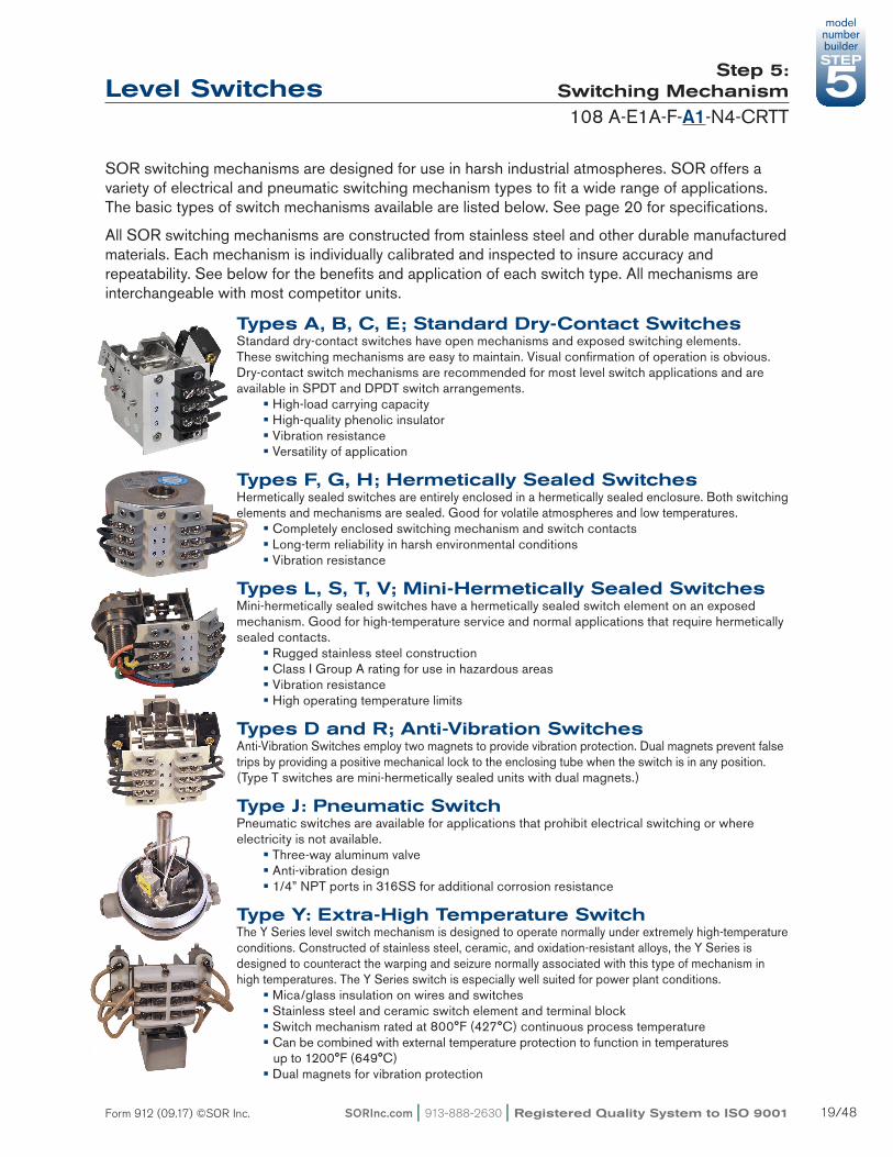
SOR switching mechanisms are designed for use in harsh industrial atmospheres. SOR offers a variety of electrical and pneumatic switching mechanism types to fit a wide range of applications. The basic types of switch mechanisms available are listed below. See page 20 for specifications.
all SOR switching mechanisms are constructed from stainless steel and other durable manufactured materials. each mechanism is individually calibrated and inspected to insure accuracy and repeatability. See below for the benefits and application of each switch type. all mechanisms are interchangeable with most competitor units.
Types A, B, C, E; Standard Dry-Contact Switches Standard dry-contact switches have open mechanisms and exposed switching elements. These switching mechanisms are easy to maintain. Visual confirmation of operation is obvious. Dry-contact switch mechanisms are recommended for most level switch applications and are available in SPDT and DPDT switch arrangements. § High-load carrying capacity § High-quality phenolic insulator § Vibration resistance § Versatility of application
Types F, G, H; Hermetically Sealed Switches Hermetically sealed switches are entirely enclosed in a hermetically sealed enclosure. Both switching elements and mechanisms are sealed. Good for volatile atmospheres and low temperatures. § Completely enclosed switching mechanism and switch contacts § Long-term reliability in harsh environmental conditions § Vibration resistance
Types L, S, T, V; Mini-Hermetically Sealed Switches mini-hermetically sealed switches have a hermetically sealed switch element on an exposed mechanism. Good for high-temperature service and normal applications that require hermetically sealed contacts. § Rugged stainless steel construction § Class I Group a rating for use in hazardous areas § Vibration resistance § High operating temperature limits
Types D and R; Anti-Vibration Switches anti-Vibration Switches employ two magnets to provide vibration protection. Dual magnets prevent false trips by providing a positive mechanical lock to the enclosing tube when the switch is in any position.(Type T switches are mini-hermetically sealed units with dual magnets.)
Type J: Pneumatic Switch Pneumatic switches are available for applications that prohibit electrical switching or where electricity is not available. § Three-way aluminum valve § anti-vibration design § 1/4” NPT ports in 316SS for additional corrosion resistance
Type Y: Extra-High Temperature Switch TheYSerieslevelswitchmechanismisdesignedtooperatenormallyunderextremelyhigh-temperatureconditions.Constructedofstainlesssteel,ceramic,andoxidation-resistantalloys,theYSeriesisdesigned to counteract the warping and seizure normally associated with this type of mechanism in hightemperatures.TheYSeriesswitchisespeciallywellsuitedforpowerplantconditions. § mica/glass insulation on wires and switches § Stainless steel and ceramic switch element and terminal block § Switch mechanism rated at 800°F (427°C) continuous process temperature § Can be combined with external temperature protection to function in temperatures up to 1200°F (649°C) § Dual magnets for vibration protection
Notes1. minimum ambient temperature at which the switch mechanism will operate normally. This may vary according to actual climatic conditions. actual minimum process temperature may be much lower. Consult the factory for details.2. maximum process temperature at which the switch mechanism will operate normally. This can be increased according to the type of process. Refer to pages 25-26 for more details.3. -40°F Temperature rating with no icing.4. Pneumatic switches must be used with clean, dry air or gas.5. These switch designators have higher current rating for SPDT than DPDT.6. manufacturer specifications state maximum operating humidity must be <85% and minimum power rating is 100mW.7. For high humidity environments and low current (<100ma), use hermetically sealed gold contact switches (S & G switches). For high temperatures, high humidity, and low current, a “V” switch is available with gold contacts upon request.
extra-High Temperature (Ceramic)Pneumatic Non-Bleed with 316SS Fittings
Y11
---
--
Y41
---
--
-J01,2
l l l l l l l
Available with models:
100-200-300-740-800 Series108/208-400 Series700 Series
lll
l lll
l lll
lll
lll
lll
lll
lll
lll
lll
730 750(enclosures N1, N8 or B5 only)
ll
ll
ll
l l l l l ll
Notes1. These switches use two magnets and must be considered dual mechanisms when figuring minimum specific gravity.2. Pneumatic switching mechanisms must be specified with P1 housing.
SOR housings are designed to protect the switching mechanisms from harsh environmental conditions, as well as protecting the surrounding atmosphere from potential ignition sources. The basic types of housings are listed below.
General Purpose, NEMA 4x Housings§ Heavy duty cast aluminum§ all housings are rated Nema 4x (IP66) as a minimum
Explosion-Proof Housings§ available in aluminum or cast iron§ Ratings as shown in chart below
Pneumatic Switch Housings§ Required for use with a pneumatic switching mechanism § General Purpose, Nema 4 (IP66) only
Switch Housings Select the housings from the chart below
HousingDesignator Description
Electical/Pneumatic
ConnectionsEnclosure Rating2
Approvals Available with ModelsC
anad
a
US
a
aTe
X
IeC
ex
Ros
tech
nadz
or
INm
eTR
O
100,
200
, 300
108,
208
, 400
740,
800
700’
s
730’
s
750’
s
B1 aluminum
1” NPT
Groups B C D e F G n n £ £ £ £ £ £
B2 Cast Iron Groups B C D e F G n n £ £ £ £ £ £
B52 aluminum extended
Groups B C D e F G n n £ £
N1aluminum extended
Nema 4, 4X n £ £
N4 aluminum Nema 4, 4X £ n £ £ £ £ £ £
N7 aluminum Groups C D F G n n £ £ £ £ £ £
N8aluminum extended
Groups C D e F G n n £ £
P11 aluminum Pneumatic
(3) 1/4” NPT Nema 4, 4X £ £ £ £
S3 aluminum 1” NPT w/ m20 x
1.5 adapter3
ex d IIC T6 Gb £ n £ £ £ £ £ £ £
S82 Cast Iron ex d IIC T6 n £ £ £ £ £ £
T62 Cast Iron ex d IIC T6 Gb n n £ £ £ £ £ £
£ — available n — StandardNotes:1. P1 housing must be used with pneumatic switch mechanisms.2. B5 housing is rated for Groups B C D e F G in Canada, and Groups C D F G in the USa.3. m20 adapters are brass. Consult factory for alternate materials.
SOR accessories are provided for customizing the level switches in this catalog according to the requirements of the application. Place accessory designator(s) from the table below at the end of the model number. Check the compatibility chart below for correct use of each accessory.
Acc
esso
ry
Des
igna
tor
Description
Model Series
100 200 108/208 300 400
741-743802
740804 700 730 750
aF1
CLair Filter & GaugeaTeX/IeCex approval for S3 Hsg
mill Test Reportmag Particle examinationNaCe ConstructionINmeTRO approved for S3 Hsg
llll
llll
llll
lll
llll
llll
llll
lll
lll
l
l
PPPTPY
RR
Fiber TagDye Penetration examinationPowder coat epoxy coating. No coating on stainless steel parts or plated screws. (500 hrs. salt spray)SS Tag wired to housing
YY epoxy Coating (enclosure only) l l l l l l l l l l
Notes: C/F = Consult the Factory 1. Pneumatic switching mechanisms only (P1) 2. Consult switch and housing sections for agency availability. 3. Process media must be known prior to manufacture. Different processes (service categories) require different quality inspection procedures. Consult the factory for details. 4. appropriate for model Series 701 through 704 & 730 through 733. See page 28 for details. Not available with NaCe. 5. See high-temperature selection for application. Pages 26-27
6. Not available with agency-listed housings. 7. Not available with T6 and S3 (aTeX) housings. 8. Need connection size, type, and location on chamber. 9. The upper & lower specific gravity required to determine functionality. 10. No mT option on Stainless Steel 11. Operating specific gravity, Set Point (referenced from upper process connection) and if Set Point is rising or falling are required. 12. Specific details of chamber dimensional changes. 13. Length of cable required (10 ft. is standard).
SOR level switches can accommodate high-temperature applications up to 1200°F (649°C). These temperatures may be safely reached by a proper combination of chamber material, switch mechanism and temperature extension. Refer to page 26 to select the proper components for your process temperature.
ET Accessory
The straight temperature extension provides physical distance between the process and the switching mechanism. It is constructed of a straight piece of pipe welded between the chamber and enclosing tube connection.
How It WorksThe straight temperature extension is designed to remove the switch from direct radiant heat in dry heat processes. Consult the chart on page 26 for application.
To Specifyadd accessory Designator eT to the end of the SOR level switch model number per the selection chart on page 26.
The eT accessory automatically matches the material and rating of the specified level switch chamber. This option can be supplied on SOR level switches 100, 200, 300 and 400 Series.
FE Accessories
The finned temperature extension is designed to protect the electrical portion of a level switch from heat damage due to condensing processes. When used in combination with high-temperature switch mechanisms, this option allows operation in process temperatures up to 1200oF (649oC).
How It WorksThe finned temperature extension condenses process steam and reduces its heat before it can reach the switching mechanism. The design reduces steam to its saturation temperature in the enclosing tube, protecting the switching mechanism from deterioration due to high temperatures. The process pressure dictates the saturation temperature, see page 32.
To Specifyadd accessory Designator Fe to the end of the SOR level switch model number per the selection chart on page 26.
The finned temperature extension automatically matches the material and rating of the specified level switch chamber. These options can be supplied on SOR level switches 100, 200,108/208, 300 and 400 Series.
Note: For proper cooling, temperature extensions must not be insulated or placed inside an enclosed structure. High ambient temperatures (over 100oF/38oC), intense direct sunlight, or heat loading from adjacent piping or vessels will affect cooling performance. Consult the factory if any of these conditions exist.
ISO-9001
14685 W 105TH ST LENEXA, KS 66215 USA913-888-2630SORINC.COM
180.97.12
101.64.00
*228.69.00
DRAWING NUMBER
0390676
Model Name: MODEL NAME.DRAFT/2/1+
PRODUCT CERTIFICATION DRAWINGALL DIMENSIONS ARE ±1/16 INUNLESS OTHERWISE SPECIFIED
MMLINEAR = IN
DRAWN BY
M SMITHCHECKED BY
J REHMENGINEER APPROVAL
J FIFEDATE
3/15/11THIS DRAWING IS THE EXCLUSIVE PROPERTY OF SOR.
NO USE WHATSOEVER OF THE INFORMATION CONTAINEDHEREON, NOR REPRODUCTION IN WHOLE OR PART MAY BE
MADE WITHOUT THE EXPRESS WRITTEN PERMISSION OF SOR.
TITLE
DIM DWG STRAIGHT TEMP EXTENSION
EO NUMBER: 5090
SCALE: DRAWING SCALE
DO NOT SCALE PRINT
DRAWING NUMBER REV
0390676 2
SHEET 1 OF 1DWG SIZE
A
MODEL #
LINE ITEM #
SALES ORDER #
PURCHASE ORDER #
146.1* MINIMUM OVERHEAD CLEARANCE5.75 REQUIRED TO REMOVE HOUSING COVER
Fundamental differences in condensing (steam) and non-condensing (dry) heat require different methods of protection.
Steam Heat processes carry it’s heat with the vapor. These processes effectively heat every portion of their enclosure. To reduce the heat effects of condensing processes, we must either condense or physically block the vapor. SOR uses a condensing system to avoid the sealing problems associated with blocking the steam.
Dry Heat processes transfer heat through direct conduction. Heat is only passed to the areas where they touch the enclosure. Therefore, radiant heat is the only concern with these processes. This may be resolved by adding distance between the process and the protected portion of the control.
Using the charts below, find your desired maximum temperature and select a corresponding chamber material. In the process type chart, select a switch mechanism based on whether you are using Steam Heat or Dry Heat. The symbol will indicate if a temperature reduction device is required.
For proper cooling, temperature extensions and finned extensions must not be insulated or placed inside an enclosed structure. High ambient temperatures (over 100ºF/38ºC), intense direct sunlight or heat loading from adjacent piping or vessels will affect cooling performance. Consult the factory if any of these conditions exist.
n = Switch Only v = Finned extension l = Temperature extension
manual Check (mC) and Tru-Check (TC) options permit manual actuation of vertical displacer level switches, addressing ePa and OSHa safety requirements. The standard 30-foot stainless steel chain allows manual actuation from the tank base, eliminating potentially hazardous trips to the top of the tank. Specify either an mC or TC option by placing the designator in the accessory section of the model number.
Designator Application
TC Tanks or vessels pressurized to 100 psi
mC atmospheric vented tanks or vessels
These options are available on SOR level switch Series 701 through 704 and 730 through 733. mC and TC option available on carbon steel units only. Series 730 through 733 are more sensitive to both high and low SG values. Please consult factory before ordering the mC or TC options for these models.
How It WorksPulling the handle transfers downward motion to the actuator lever by means of the beaded stainless steel chain. The resultant motion lifts the entire level sensing assembly which moves the attraction sleeve and actuates the switching element to simulate a high-level condition.Switching action for alarm, shutdown or control is verified.
Dimensions
Product Specifications
Pressure Range TC (Tru-Check) *0 to 100 psi MC (Manual Check) 0 psi (vented to atmosphere)
*maximum pressure for entire level sensing assembly is 100 psi with Tru-Check installed.
Temperature Range -40 to 300°F (–40 to 150°C)Wetted Parts Ball Chrome Plated Brass Seal Teflon Spring Spring Steel Body 1018 Steel
Design and specifications are subject to change without notice. For latest revision, see www.sorinc.com.
ISO-9001
14685 W 105TH ST LENEXA, KS 66215 USA913-888-2630SORINC.COM
101.64.00
229.49.03
*456.417.97
393.715.50
CUSTOMERSPECIFIED
DIMENSION
Model Name: 0390674.ASSEM/1/5+
PRODUCT CERTIFICATION DRAWINGALL DIMENSIONS ARE ±1/16 INUNLESS OTHERWISE SPECIFIED
MMLINEAR = IN
DRAWN BY
K MITCHELLCHECKED BY
M SMITHENGINEER APPROVAL
J FIFEDATE
16 MAY 2011THIS DRAWING IS THE EXCLUSIVE PROPERTY OF SOR.
NO USE WHATSOEVER OF THE INFORMATION CONTAINEDHEREON, NOR REPRODUCTION IN WHOLE OR PART MAY BE
MADE WITHOUT THE EXPRESS WRITTEN PERMISSION OF SOR.
TITLE
DIM DWG 700 SERIES W/MANUAL CHECK
EO NUMBER: 5116
SCALE: 0.20
DO NOT SCALE PRINT
DRAWING NUMBER REV
0390674 3
SHEET 1 OF 1DWG SIZE
B
MODEL # SALES ORDER # LINE ITEM # PURCHASE ORDER #
ELECTRICALCONNECTION "W"
146.1* MINIMUM OVERHEAD CLEARANCE5.75 REQUIRED TO REMOVE HOUSING COVER
ASME B31.3 Fluid CategoryNormal a fluid service not subject to the following four categories.
Category D a fluid service in which all of the following apply: 1. The fluid handled is non-flammable, non-toxic, and not damaging to human skin. 2. The design gage pressure does not exceed 150 psi. 3. The design temperature is between -20°F and 366°F.
Category M a fluid service in which the potential for personnel exposure is judged to be significant and in which a single exposure to a very small quantity of a toxic fluid, caused by leakage, can produce serious irreversible harm to persons on breathing or bodily contact, even when prompt restorative measures are taken.
High Pressure Pressure in excess of that allowed by the aSme B16.5 Class 2500 rating for the specified temperature and material group or any piping so designated by the customer.
If certification to B31.3 is required, SOR Inc. must know the fluid category per the chart below. Read the aSme B31.3 Fluid Category Section at the bottom of this page to determine the applicable category.
Units Covered Visual Examination1
Radiographic (X-Ray) RT
Magnetic Particle MT
Dye Penetrant PT Hydrotest
Standard Inspection
all Chambers 100% 0% 0% 0%1.5 x pressure for
3 minutes
CY Option (ASME B31.1)
Below 750°FBelow 1025 psi
100% - - -
1.5 x pressure for 10 minutes
Below 350°F all pressures
100% - - -
350°F - 750°Fabove 1025 psi
100% all butt welds >2” - -
above 750°F all pressures
100% all butt welds >2”Butt welds >2” all
other weldsButt welds >2” all
other welds
CZ Option (ASME B31.3)
Normal Fluid 5% 5%2 - -
1.5 x pressure for 10 minutes
Category Dengineering/Qa
Choice- - -
Category m 100% 20% of all welds3 - -
High Pressure 100%100% of girth/branch welds
- -
Notes1. In process visual inspection: inspecting pipe bevel prior to welding, check fit-up, check after-tack weld, and check during weld passes. after completion visual inspection: welding and grinding is checked.2. In process examination may be substituted on a weld-for-weld basis.3. In process examination supplemented by appropriate NDe (mT or PT) may be substituted on a weld-for-weld basis.
SOR uses all aSTm grade materials in the construction of mechanical level switches. The following chart lists the specific aSTm (or UNS) materials that are normally used for each component in our switches. Consult the factory if you do not see the specific material required for your application.
Notes1. UNS numbers are given for special alloys.2. These materials are available by special order only.
Level Switches aSTm maTeRIaL DeSIGNaTIONS
Ring Tight Joint Flanges (RTJ)
The side surfaces of RTJ gasket surfaces shall not exceed 63µ” (1.6µm) roughness per aNSI B16.5.
Raised Face Flanges (RF)all raised-face flange finishes are given as a range. aaRH (average arithmetic Root Height) values are given with their metric equivalent.
Flange Face Finishes
The most common flange face finishes are shown in the table below.
The approximate shipping weights shown below are for standard models. Weights will vary based on pipe size, length and flange size. Consult the factory for the weight of a specific unit.
Floats Displacers
Model pounds kilograms Page Model pounds kilograms Page
101*102*103*
5580
130
253760
333333
701702703
181830
8.58.5
13.5
444444
108109*121*
13012540
595318
373333
704705706
302030
13.599
444444
122*123*124*
508090
233642
333333
707708730
323220
14.514.5
9
444445
201*202*203*
452626
20.51212
353535
731732733
203232
914.514.5
454545
204*205*206*
264545
1220.520.5
353535
734735736
222234
1010
15.5
454545
207*208209*
458962
20.52229
353735
737740*741*
342848
15.512.522
454240
221*301303
221212
105.55.5
353838
742*743*750
606824
273111
404046
304401402
121512
5.57
5.5
383939
751752753
243636
111616
464646
403404405
281512
12.57
19
393939
754755756
262638
121217
464646
406 70 32 39 757802804
3818550
1782
22.5
464042
* add weights from the table below to the base model weight for VV, VVT, or VH configurations with flanges.
2” 12 5.5 16 7.5 18 8.5Weights shown in this table include two flanges, pipe nipples, and fittings.Note: Consult the factory for additional weight due to accessories or non-standard requirements.
The specific gravity of water changes depending on its temperature and pressure. The chart below lists properties of saturated steam. Saturated steam is the state where water is in transition between liquid and vapor. The chart provides the process temperature with the associated pressure and specific gravity of the condensate water. If a water application has a high temperature and low pressure, condensate will only be present at the temperature that corresponds to the maximum pressure. Select the proper row based on the temperature and pressure, and read the specific gravity.
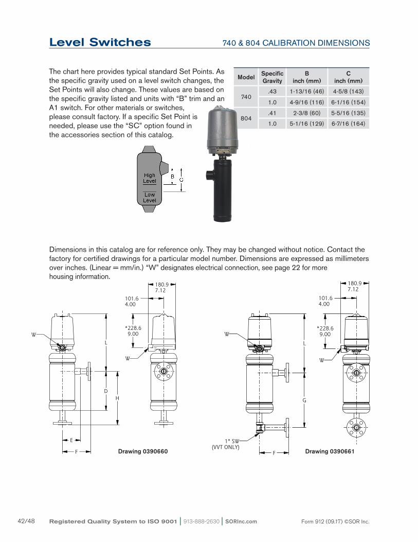
The chart here provides typical standard Set Points. as the specific gravity used on a level switch changes, the Set Points will also change. These values are based on the specific gravity listed and units with “B” trim and an a1 switch. For other materials or switches, please consult factory. If a specific Set Point is needed, please use the “SC” option found in the accessories section of this catalog.
Chamber Dimensions listed are for reference only and are expressed as millimeters over inches. (Linear = mm/in.) They are subject to change without notice. Contact SOR for certified drawings of particular models or if special dimensions are required. “W” designates electrical connection, see page 22 for more housing information.
Drawing 0390019
ISO-9001
14685 W 105TH ST LENEXA, KS 66215 USA913-888-2630SORINC.COM
L
DH
E
F
*228.69.00
101.64.00
180.97.12
DRAWING NUMBER
0390019
Model Name: MODEL NAME.DRAFT/3/1+
PRODUCT CERTIFICATION DRAWINGALL DIMENSIONS ARE ±1/16 INUNLESS OTHERWISE SPECIFIED
MMLINEAR = IN
DRAWN BY
M SMITHCHECKED BY
J REHMENGINEER APPROVAL
J FIFEDATE
3/14/11THIS DRAWING IS THE EXCLUSIVE PROPERTY OF SOR.
NO USE WHATSOEVER OF THE INFORMATION CONTAINEDHEREON, NOR REPRODUCTION IN WHOLE OR PART MAY BE
MADE WITHOUT THE EXPRESS WRITTEN PERMISSION OF SOR.
TITLE
DIM DWG 100 SERIES SERVICEABLEEXTERNAL CHAMBER VH STYLE
EO NUMBER: 5090
SCALE: DRAWING SCALE
DO NOT SCALE PRINT
DRAWING NUMBER REV
0390019 3
SHEET 1 OF 1DWG SIZE
A
MODEL #
LINE ITEM #
SALES ORDER #
PURCHASE ORDER #
146.1* MINIMUM OVERHEAD CLEARANCE5.75 REQUIRED TO REMOVE HOUSING COVER.
W
W
THIS DRAWING WAS CREATED USINGTHE VERTICAL_MOUNT_ASSY AND TEXTFILE 0390019.txt LOCATED ON THEK:\$Engineering Services\Concept text filesTHEN THE DRAWING WAS CHANGED TODRAFT ENTITIES.
Reset Form
Drawing 0390021
ISO-9001
14685 W 105TH ST LENEXA, KS 66215 USA913-888-2630SORINC.COM
G
L
F
180.97.12
101.64.00
*228.69.00
DRAWING NUMBER
0390021
Model Name: MODEL NAME.DRAFT/3/0+
PRODUCT CERTIFICATION DRAWINGALL DIMENSIONS ARE ±1/16 INUNLESS OTHERWISE SPECIFIED
MMLINEAR = IN
DRAWN BY
M SMITHCHECKED BY
J REHMENGINEER APPROVAL
J FIFEDATE
3/15/11THIS DRAWING IS THE EXCLUSIVE PROPERTY OF SOR.
NO USE WHATSOEVER OF THE INFORMATION CONTAINEDHEREON, NOR REPRODUCTION IN WHOLE OR PART MAY BE
MADE WITHOUT THE EXPRESS WRITTEN PERMISSION OF SOR.
TITLE
DIM DWG 100 SERIES SERVICEABLEEXTERNAL CHAMBER VV, VVT STYLE
EO NUMBER: 5090
SCALE: DRAWING SCALE
DO NOT SCALE PRINT
DRAWING NUMBER REV
0390021 3
SHEET 1 OF 1DWG SIZE
A
MODEL #
LINE ITEM #
SALES ORDER #
PURCHASE ORDER #
146.1* MINIMUM OVERHEAD CLEARANCE5.75 REQUIRED TO REMOVE HOUSING COVER.
THIS DRAWING WAS CREATED USINGTHE VERTICAL_MOUNT_ASSY AND TEXTFILE 0390021.txt LOCATED ON THEK:\$Engineering Services\Concept text filesTHEN THE DRAWING WAS CHANGED TODRAFT ENTITIES.
W
W
1" SW(VVT ONLY)
Reset Form
Drawing 0390010
ISO-9001
14685 W 105TH ST LENEXA, KS 66215 USA913-888-2630SORINC.COM
I
355.614.00
L
F
E
*228.69.00
180.97.12
101.64.00
DRAWING NUMBER
0390010
Model Name: MODEL NAME.DRAFT/3/0+
PRODUCT CERTIFICATION DRAWINGALL DIMENSIONS ARE ±1/16 INUNLESS OTHERWISE SPECIFIED
MMLINEAR = IN
DRAWN BY
M SMITHCHECKED BY
J REHMENGINEER APPROVAL
J FIFEDATE
3/14/11THIS DRAWING IS THE EXCLUSIVE PROPERTY OF SOR.
NO USE WHATSOEVER OF THE INFORMATION CONTAINEDHEREON, NOR REPRODUCTION IN WHOLE OR PART MAY BE
MADE WITHOUT THE EXPRESS WRITTEN PERMISSION OF SOR.
TITLE
DIM DWG 100 SERIES SERVICEABLEEXTERNAL CHAMBER VVD STYLE
EO NUMBER: 5090
SCALE: DRAWING SCALE
DO NOT SCALE PRINT
DRAWING NUMBER REV
0390010 3
SHEET 1 OF 1DWG SIZE
A
MODEL #
LINE ITEM #
SALES ORDER #
PURCHASE ORDER #
146.1* MINIMUM OVERHEAD CLEARANCE5.75 REQUIRED TO REMOVE HOUSING COVER.
DRAIN CONN1"NPT OR SW
W
W
THIS DRAWING WAS CREATED USINGTHE VERTICAL_MOUNT_ASSY AND TEXTFILE 0390010.txt LOCATED ON THEK:\$Engineering Services\Concept text filesTHEN THE DRAWING WAS CHANGED TODRAFT ENTITIES.
Notes 1. Dimensions D and e apply to socket-weld connections only. Consult factory for NPT dimensions.2. Consult factory for dimensions for materials other than carbon steel.3. applies to socket weld or NPT process connections only.4. Consult the factory if weld neck process flanges are required. Dimensions may vary from those shown above.5. applies to flanged process connections only.
The chart here provides typical standard Set Points. as the specific gravity used on a level switch changes, the Set Points will also change. These values are based on the specific gravity listed and units with “B” trim and an a1 switch. For other materials or switches, please consult factory. If a specific Set Point is needed, please use the “SC” option found in the accessories section of this catalog.
200 SeRIeS CaLIBRaTION DImeNSIONS
Model Specific Gravity
Binch (mm)
Cinch (mm)
201.38 3-3/16 (81) 4 (102)
1.0 5-3/16 (132) 5-9/16 (141)
202.52 3-1/4 (83) 4-7/16 (113)
1.0 5-1/4 (133) 5-15/16 (151)
203.61 3 (76) 4-1/16 (103)
1.0 4-3/4 (121) 5-7/16 (138)
204.91 3 (76) 3-15/16 (100)
1.0 3-3/8 (86) 4-1/4 (108)
205.50 3 (76) 3-11/16 (94)
1.0 4-11/16 (119) 5 (127)
206.65 3-1/2 (89) 4-1/4 (108)
1.0 4-5/8 (117) 5-1/16 (129)
207.61 3 (76) 3-9/16 (90)
1.0 4-5/16 (110) 4-5/8 (117)
209.38 4-3/4 (121) 5-1/4 (133)
1.0 7-1/4 (184) 7-1/2 (191)
221.64 2-9/16 (65) 4-1/16 (103)
1.0 3-13/16 (97) 4-13/16 (122)
Level Switches
Dimensions listed are for reference only and are expressed as millimeters over inches. (Linear = mm/in.) They are subject to change without notice. Contact SOR for certified drawings of particular models or if special dimensions are required. “W” designates electrical connection, see page 22 for more housing information.
Drawing 0390660
ISO-9001
14685 W 105TH ST LENEXA, KS 66215 USA913-888-2630SORINC.COM
E
F
DH
L
180.97.12
101.64.00
*228.69.00
DRAWING NUMBER
0390660
Model Name: MODEL NAME.DRAFT/2/0+
PRODUCT CERTIFICATION DRAWINGALL DIMENSIONS ARE ±1/16 INUNLESS OTHERWISE SPECIFIED
MMLINEAR = IN
DRAWN BY
M SMITHCHECKED BY
J REHMENGINEER APPROVAL
J FIFEDATE
3/15/11THIS DRAWING IS THE EXCLUSIVE PROPERTY OF SOR.
NO USE WHATSOEVER OF THE INFORMATION CONTAINEDHEREON, NOR REPRODUCTION IN WHOLE OR PART MAY BE
MADE WITHOUT THE EXPRESS WRITTEN PERMISSION OF SOR.
TITLE
DIM DWG 200 SERIES SEALED CHAMBERVH
EO NUMBER: 5090
SCALE: DRAWING SCALE
DO NOT SCALE PRINT
DRAWING NUMBER REV
0390660 2
SHEET 1 OF 1DWG SIZE
A
MODEL #
LINE ITEM #
SALES ORDER #
PURCHASE ORDER #
146.1* MINIMUM OVERHEAD CLEARANCE5.75 REQUIRED TO REMOVE HOUSING COVER.
THIS DRAWING WAS CREATED USINGTHE VERTICAL_MOUNT_ASSY AND TEXTFILE 0390660.txt LOCATED ON THEK:\$Engineering Services\Concept text filesTHEN THE DRAWING WAS CHANGED TODRAFT ENTITIES.
W
W
Reset Form
ISO-9001
14685 W 105TH ST LENEXA, KS 66215 USA913-888-2630SORINC.COM
I
355.614.00
L
E
F
180.97.12
101.64.00
*228.69.00
DRAWING NUMBER
0390662
Model Name: MODEL NAME.DRAFT/1/3+
PRODUCT CERTIFICATION DRAWINGALL DIMENSIONS ARE ±1/16 INUNLESS OTHERWISE SPECIFIED
MMLINEAR = IN
DRAWN BY
M SMITHCHECKED BY
J REHMENGINEER APPROVAL
J FIFEDATE
3/15/11THIS DRAWING IS THE EXCLUSIVE PROPERTY OF SOR.
NO USE WHATSOEVER OF THE INFORMATION CONTAINEDHEREON, NOR REPRODUCTION IN WHOLE OR PART MAY BE
MADE WITHOUT THE EXPRESS WRITTEN PERMISSION OF SOR.
TITLE
DIM DWG 200 SERIES SEALED CHAMBERVVD
EO NUMBER: 5090
SCALE: DRAWING SCALE
DO NOT SCALE PRINT
DRAWING NUMBER REV
0390662 2
SHEET 1 OF 1DWG SIZE
A
MODEL #
LINE ITEM #
SALES ORDER #
PURCHASE ORDER #
146.1* MINIMUM OVERHEAD CLEARANCE5.75 REQUIRED TO REMOVE HOUSING COVER.
THIS DRAWING WAS CREATED USINGTHE VERTICAL_MOUNT_ASSY AND TEXTFILE 0390662.txt LOCATED ON THEK:\$Engineering Services\Concept text filesTHEN THE DRAWING WAS CHANGED TODRAFT ENTITIES.
W
W
DRAIN CONN1"NPT OR SW
Reset Form
ISO-9001
14685 W 105TH ST LENEXA, KS 66215 USA913-888-2630SORINC.COM
F
G
L
180.97.12
101.64.00
*228.69.00
DRAWING NUMBER
0390661
Model Name: MODEL NAME.DRAFT/1/4+
PRODUCT CERTIFICATION DRAWINGALL DIMENSIONS ARE ±1/16 INUNLESS OTHERWISE SPECIFIED
MMLINEAR = IN
DRAWN BY
M SMITHCHECKED BY
J REHMENGINEER APPROVAL
J FIFEDATE
3/15/11THIS DRAWING IS THE EXCLUSIVE PROPERTY OF SOR.
NO USE WHATSOEVER OF THE INFORMATION CONTAINEDHEREON, NOR REPRODUCTION IN WHOLE OR PART MAY BE
MADE WITHOUT THE EXPRESS WRITTEN PERMISSION OF SOR.
TITLE
DIM DWG 200 SERIES SEALED CHAMBERVV, VVT
EO NUMBER: 5090
SCALE: DRAWING SCALE
DO NOT SCALE PRINT
DRAWING NUMBER REV
0390661 2
SHEET 1 OF 1DWG SIZE
A
MODEL #
LINE ITEM #
SALES ORDER #
PURCHASE ORDER #
146.1* MINIMUM OVERHEAD CLEARANCE5.75 REQUIRED TO REMOVE HOUSING COVER.
THIS DRAWING WAS CREATED USINGTHE VERTICAL_MOUNT_ASSY AND TEXTFILE 0390661.txt LOCATED ON THEK:\$Engineering Services\Concept text filesTHEN THE DRAWING WAS CHANGED TODRAFT ENTITIES.
Notes 1. Dimensions D and e apply to socket-weld connections only. Consult factory for NPT dimensions.2. Consult factory for dimensions for materials other than carbon steel.3. applies to socket weld or NPT process connections only.4. Consult the factory if weld neck process flanges are required. Dimensions may vary from those shown above.5. applies to flanged process connections only.
14685 W 105TH ST LENEXA, KS 66215 USA913-888-2630SORINC.COM
A
B
*228.69.00
187.37.38
180.97.12
101.64.00
500.019.69
164.36.47
C
MODEL CONNECTIONSIZE A B C
208A(CS)
1" 125.44.94
250.89.88
399.015.71
1-1/2" 128.55.06
257.010.12
402.115.83
2" 138.25.44
276.410.88
411.716.21
208C(316SST)
1" 120.74.75
241.39.50
394.215.52
1-1/2" 130.35.13
260.610.26
403.915.90
2" 143.05.63
186.011.25
416.616.40
DRAWING NUMBER
0390666
Model Name: MODEL NAME.DRAFT/2/0+
PRODUCT CERTIFICATION DRAWINGALL DIMENSIONS ARE ±1/16 INUNLESS OTHERWISE SPECIFIED
MMLINEAR = IN
DRAWN BY
M SMITHCHECKED BY
J REHMENGINEER APPROVAL
J FIFEDATE
3/16/11THIS DRAWING IS THE EXCLUSIVE PROPERTY OF SOR.
NO USE WHATSOEVER OF THE INFORMATION CONTAINEDHEREON, NOR REPRODUCTION IN WHOLE OR PART MAY BE
MADE WITHOUT THE EXPRESS WRITTEN PERMISSION OF SOR.
TITLE
DIM DWG 208 SERIES HORIZONITALMOUNT FLOAT OPERATED
EO NUMBER: 5090
SCALE: DRAWING SCALE
DO NOT SCALE PRINT
DRAWING NUMBER REV
0390666 2
SHEET 1 OF 1DWG SIZE
A
MODEL #
LINE ITEM #
SALES ORDER #
PURCHASE ORDER #
146.1* OVERHEAD CLEARANCE5.75 REQUIRED TO REMOVE COVER.
W
THIS DRAWING WAS CREATED USINGTHE HORIZ_MOUNT_ASSY AND TEXTFILE 0390666.txt LOCATED ON THEK:\$Engineering Services\Concept text filesTHEN THE DRAWING WAS CHANGED TODRAFT ENTITIES.
Reset Form
ISO-9001
14685 W 105TH ST LENEXA, KS 66215 USA913-888-2630SORINC.COM
187.37.38
200.87.91
A
B317.512.50
C
*228.69.00
180.97.12
101.64.00
573.122.56
MODEL CONNECTIONSIZE A B C
108A(CS)
1" 125.44.94
250.89.88
399.015.71
1-1/2" 128.55.06
257.010.12
402.115.83
2" 138.25.44
276.410.88
411.716.21
108C(316SST)
1" 120.74.75
241.39.50
394.215.52
1-1/2" 130.35.13
260.610.26
403.915.90
2" 143.05.63
186.011.25
416.616.40
DRAWING NUMBER
0390667
Model Name: MODEL NAME.DRAFT/2/0+
PRODUCT CERTIFICATION DRAWINGALL DIMENSIONS ARE ±1/16 INUNLESS OTHERWISE SPECIFIED
MMLINEAR = IN
DRAWN BY
M SMITHCHECKED BY
J REHMENGINEER APPROVAL
J FIFEDATE
3/16/11THIS DRAWING IS THE EXCLUSIVE PROPERTY OF SOR.
NO USE WHATSOEVER OF THE INFORMATION CONTAINEDHEREON, NOR REPRODUCTION IN WHOLE OR PART MAY BE
MADE WITHOUT THE EXPRESS WRITTEN PERMISSION OF SOR.
TITLE
DIM DWG 108 SERIES HORIZONITALMOUNT FLOAT OPERATED
EO NUMBER: 5090
SCALE: DRAWING SCALE
DO NOT SCALE PRINT
DRAWING NUMBER REV
0390667 2
SHEET 1 OF 1DWG SIZE
A
MODEL #
LINE ITEM #
SALES ORDER #
PURCHASE ORDER #
146.1* OVERHEAD CLEARANCE5.75 REQUIRED TO REMOVE COVER.
THIS DRAWING WAS CREATED USINGTHE HORIZ_MOUNT_ASSY AND TEXTFILE 0390667.txt LOCATED ON THEK:\$Engineering Services\Concept text filesTHEN THE DRAWING WAS CHANGED TODRAFT ENTITIES.
W
Reset Form
Model 108
Drawing 0390667
Model 208
Drawing 0390666
108/208 CHamBeR DImeNSIONS
Dimensions listed are for reference only and are expressed as millimeters over inches. (Linear = mm/in.) They are subject to change without notice. Contact SOR for certified drawings of particular models or if special dimensions are required. “W” designates electrical connection, see page 22 for more housing information.
Model Connection Size
A B C
inch (mm) inch (mm) inch (mm)
108
1” 4-13/16 (122)* 9-5/8 (244)* 15-1/2 (394)
1-1/2” 5-1/16 (129)* 10-1/8 (258)* 15-3/4 (401)*
2” 5-3/8 (137)* 10-3/4 (274)* 16-1/8 (409)*
208
1” 4-15/16 (125) 9-7/8 (250) 15-5/8 (396)
1-1/2” 5-1/16 (129)* 10-1/8 (258)* 15-3/4 (401)*
2” 5-3/8 (137)* 10-3/4 (274)* 16-1/8 (409)**Dimensions valid for socket weld process connections. Consult factory for threaded connection dimensions.
Dimensions in this catalog are for reference only. They may be changed without notice. Contact the factory for certified drawings for a particular model number. Dimensions are expressed as millimeters over inches. (Linear = mm/in.) “W” designates electrical connection, see page 22 for more housing information.
ISO-9001
14685 W 105TH ST LENEXA, KS 66215 USA913-888-2630SORINC.COM
101.64.00
180.97.12
99.23.91
FLOAT
227.08.94
Model Name: 0390053.ASSEM/3/3+
PRODUCT CERTIFICATION DRAWINGALL DIMENSIONS ARE ±1/16 INUNLESS OTHERWISE SPECIFIED
MMLINEAR = IN
DRAWN BY
J REHMCHECKED BY
M SMITHENGINEER APPROVAL
J FIFEDATE
3/6/12THIS DRAWING IS THE EXCLUSIVE PROPERTY OF SOR.
NO USE WHATSOEVER OF THE INFORMATION CONTAINEDHEREON, NOR REPRODUCTION IN WHOLE OR PART MAY BE
MADE WITHOUT THE EXPRESS WRITTEN PERMISSION OF SOR.
TITLE
DIM DWG 300 SERIES 1" NPT(FLOAT OPERATED)
EO NUMBER: 5154
SCALE: 0.33
DO NOT SCALE PRINT
DRAWING NUMBER REV
0390053 4
SHEET 1 OF 1DWG SIZE
B
NOTES:1. FLOAT SIZE IS BASED ON MINIMUM DIFFERENTIAL SETTING, MINIMUM LIQUID SPECIFIC GRAVITY, AND SINGLE SWITCH FUNCTION.2. CAUTION MUST BE USED IN SELECTING MOUNTING NOZZLE PIPE SCHEDULE TO PROVIDE FLOAT INSERTION CLEARANCE.
PROCESSCONNECTION1 NPT(M)
W
Drawing 0390053
ISO-9001
14685 W 105TH ST LENEXA, KS 66215 USA913-888-2630SORINC.COM
C
101.64.00
180.97.12
FLOAT
227.08.94
Model Name: 0390007.ASSEM/3/0+
PRODUCT CERTIFICATION DRAWINGALL DIMENSIONS ARE ±1/16 INUNLESS OTHERWISE SPECIFIED
MMLINEAR = IN
DRAWN BY
J REHMCHECKED BY
M SMITHENGINEER APPROVAL
J FIFEDATE
3/6/12THIS DRAWING IS THE EXCLUSIVE PROPERTY OF SOR.
NO USE WHATSOEVER OF THE INFORMATION CONTAINEDHEREON, NOR REPRODUCTION IN WHOLE OR PART MAY BE
MADE WITHOUT THE EXPRESS WRITTEN PERMISSION OF SOR.
TITLE
DIM DWG 300 SERIES FLANGEDFLOAT OPERATED
EO NUMBER: 5154
SCALE: 0.33
DO NOT SCALE PRINT
DRAWING NUMBER REV
0390007 4
SHEET 1 OF 1DWG SIZE
B
NOTES: 1. FLOAT SIZE IS BASED ON MINIMUM DIFFERENTIAL SETTING, MINIMUM LIQUID SPECIFIC GRAVITY, AND SINGLE SWITCH FUNCTION. 2. CAUTION MUST BE USED IN SELECTING MOUNTING NOZZLE PIPE SCHEDULE TO PROVIDE FLOAT INSERTION CLEARANCE.
W
PROCESSCONNECTIONFLANGE B
Drawing 0390007
ISO-9001
14685 W 105TH ST LENEXA, KS 66215 USA913-888-2630SORINC.COM
62.72.47
C
A
B
227.08.94
180.97.12
101.64.00
A
C
B
62.72.47
227.08.94
101.64.00
180.97.12
MODEL FLOAT SIZE
301 139.75.50
303 88.9 152.4 X 3.5 6.00
304 13.75.50
Model Name: 0390665_OPT.ASSEM//0
PRODUCT CERTIFICATION DRAWINGALL DIMENSIONS ARE ±1/16 INUNLESS OTHERWISE SPECIFIED
MMLINEAR = IN
DRAWN BY
M SMITHCHECKED BY
K MITCHELLENGINEER APPROVAL
R CARLSONDATE
4/4/13THIS DRAWING IS THE EXCLUSIVE PROPERTY OF SOR.
NO USE WHATSOEVER OF THE INFORMATION CONTAINEDHEREON, NOR REPRODUCTION IN WHOLE OR PART MAY BE
MADE WITHOUT THE EXPRESS WRITTEN PERMISSION OF SOR.
TITLE
DIM DWG 300 SERIES FLANGED TANDEM(FLOAT OPERATED)
EO NUMBER: 5195
SCALE: 0.20
DO NOT SCALE PRINT
DRAWING NUMBER REV
0390665 2
SHEET 1 OF 1DWG SIZE
B
MODEL # SALES ORDER # LINE ITEM # PURCHASE ORDER #SALES PAGE
146.1* OVERHEAD CLEARANCE5.75 REQUIRED TO REMOVE COVER.
NOTE:1. FLOAT SIZE IS BASED ON MINIMUM DIFFERENTIAL SETTING, MINIMUM LIQUID SPECIFIC GRAVITY, AND SINGLE SWITCH FUNCTION.2. CAUTION MUST BE USED IN SELECTING MOUNTING NOZZLE PIPE SCHEDULE TO PROVIDE FLOAT INSERTION CLEARANCE.
MODEL301/304
MODEL303
W
PROCESSCONNECTIONFLANGE D
UPPER FLOAT
LOWER FLOAT
W
PROCESSCONNECTIONFLANGE D
UPPER FLOAT
LOWER FLOAT
2
2
1
Reset Form
Drawing 0390665
300 SeRIeS UNIT DImeNSIONS
Standard Units
Tandem Float Unit
Standard Units
Series Float SizeMinimumInsertion
Maximum Insertion
inch (mm) inch (mm)
303 3-1/2 x 6” 4-1/2 (114)
48 (1219)3015-1/2” 4-1/4 (108)
304** See Housing section (page 22).*** m20 adapters are brass. Contact the factory for alternate materials.
Tandem Float Units in inches (mm)
Series Float SizeHigh Insertion Low Insertion Differential
304Notes1. Standard Units: It is important to consider the installation configuration when selecting the process connection. Be
sure that the float will fit through the process connection, or that the vessel has access to attach the float from inside the vessel after instrument installation. minimum 5-3/4’’ (146 mm) overhead clearance required to remove housing cover.
2. Tandem Float Units: It is important to consider the installation configuration when selecting the process connection. Be sure that the float will fit through the process connection. Tandem floats are not removable and must be installed through the nozzle opening. Operating specific gravity and insertion depths must be specified. minimum 5-3/4’’ (146 mm) overhead clearance required to remove housing cover.
14685 W 105TH ST LENEXA, KS 66215 USA913-888-2630SORINC.COM
D
45718.0
N
118.34.66
101.64.00
180.97.12
*227.08.94
FLOAT
263.510.38
217.58.56 MAXIMUM DIFFERENTIAL (D)
FLANGEDUNITS NOZZLE LENGTH (N)
MODEL 512.0
1024.0
1526.0
2038.0
25410.0
403 33013.0
2299.0
1787.0
1275.0
1144.5
405**1526.0
1275.0
406**
STANDARD DIFFERENTIAL (D)
MODEL "D" @ MIN. S.G.
403 512.0
40544.51.75
406
Model Name: 0390669.ASSEM/1/5+
PRODUCT CERTIFICATION DRAWINGALL DIMENSIONS ARE ±1/16 INUNLESS OTHERWISE SPECIFIED
MMLINEAR = IN
DRAWN BY
K MITCHELLCHECKED BY
J REHMENGINEER APPROVAL
J FIFEDATE
08 APR 2011THIS DRAWING IS THE EXCLUSIVE PROPERTY OF SOR.
NO USE WHATSOEVER OF THE INFORMATION CONTAINEDHEREON, NOR REPRODUCTION IN WHOLE OR PART MAY BE
MADE WITHOUT THE EXPRESS WRITTEN PERMISSION OF SOR.
TITLE
DIM DWG 403,405,406FLOAT OPERATED
EO NUMBER: 5090
SCALE: 0.33
DO NOT SCALE PRINT
DRAWING NUMBER REV
0390669 2
SHEET 1 OF 1DWG SIZE
B
MODEL # SALES ORDER # LINE ITEM # PURCHASE ORDER #
146.1* MINIMUM OVERHEAD CLEARANCE5.75 REQUIRED TO REMOVE HOUSING COVER.
**BASED ON 4" FLANGE SIZE
NOTES: 1. STANDARD DIFFERENTIAL. FOR MAXIMUM DIFFERENTIAL, SEE TABLE.ELECTRICAL CONN. "W" : __________
PROCESSCONNECTION
WELD NECKFLANGE
CUSTOMERPROCESSCONNECTION
W
1
1
1
Reset Form
Models 403, 405, 406
Drawing 0390669
Dimensions in this catalog are for reference only. They may be changed without notice. Contact the factory for certified drawings for a particular model number. Dimensions are expressed as millimeters over inches. (Linear = mm/in.) “W” designates electrical connection, see page 22 for more housing information.
Standard Differential (D)
ModelD @ Minimum
Specific Gravity
inch (mm)
401
3 (76)402
403
404
4052-3/4 (70)
406Note: With anti-vibration, extra-high temperature and pneumatic switch, minimum differential will increase.
ModelFlanged Units - Customer Nozzle Length (N)
2 (51) 4 (102) 6 (152) 8 (203) 10 (254)
403 13 (330) 9 (229) 7 (178) 5 (127) 4-1/2 (114)
405*6 (152) 5 (127)
406**Based on 4-inch flange size.
Maximum Differential (D) Differential Dimension “D” is calibrated to the minimum shown above as standard. Wider differentials are available by placing an SC in the accessory section of the model number. The charts below give the maximum differentials available.
The chart here provides typical standard Set Points. as the specific gravity used on a level switch changes, the Set Points will also change. These values are based on the specific gravity listed and units with “B” trim and an a1 switch. For other materials or switches, please consult factory. If a specific Set Point is needed, please use the “SC” option found in the accessories section of this catalog.
ISO-9001
14685 W 105TH ST LENEXA, KS 66215 USA913-888-2630SORINC.COM
G
L
F
180.97.12
101.64.00
*228.69.00
DRAWING NUMBER
0390021
Model Name: MODEL NAME.DRAFT/3/0+
PRODUCT CERTIFICATION DRAWINGALL DIMENSIONS ARE ±1/16 INUNLESS OTHERWISE SPECIFIED
MMLINEAR = IN
DRAWN BY
M SMITHCHECKED BY
J REHMENGINEER APPROVAL
J FIFEDATE
3/15/11THIS DRAWING IS THE EXCLUSIVE PROPERTY OF SOR.
NO USE WHATSOEVER OF THE INFORMATION CONTAINEDHEREON, NOR REPRODUCTION IN WHOLE OR PART MAY BE
MADE WITHOUT THE EXPRESS WRITTEN PERMISSION OF SOR.
TITLE
DIM DWG 100 SERIES SERVICEABLEEXTERNAL CHAMBER VV, VVT STYLE
EO NUMBER: 5090
SCALE: DRAWING SCALE
DO NOT SCALE PRINT
DRAWING NUMBER REV
0390021 3
SHEET 1 OF 1DWG SIZE
A
MODEL #
LINE ITEM #
SALES ORDER #
PURCHASE ORDER #
146.1* MINIMUM OVERHEAD CLEARANCE5.75 REQUIRED TO REMOVE HOUSING COVER.
THIS DRAWING WAS CREATED USINGTHE VERTICAL_MOUNT_ASSY AND TEXTFILE 0390021.txt LOCATED ON THEK:\$Engineering Services\Concept text filesTHEN THE DRAWING WAS CHANGED TODRAFT ENTITIES.
W
W
1" SW(VVT ONLY)
Reset Form
ISO-9001
14685 W 105TH ST LENEXA, KS 66215 USA913-888-2630SORINC.COM
L
DH
E
F
*228.69.00
101.64.00
180.97.12
DRAWING NUMBER
0390019
Model Name: MODEL NAME.DRAFT/3/1+
PRODUCT CERTIFICATION DRAWINGALL DIMENSIONS ARE ±1/16 INUNLESS OTHERWISE SPECIFIED
MMLINEAR = IN
DRAWN BY
M SMITHCHECKED BY
J REHMENGINEER APPROVAL
J FIFEDATE
3/14/11THIS DRAWING IS THE EXCLUSIVE PROPERTY OF SOR.
NO USE WHATSOEVER OF THE INFORMATION CONTAINEDHEREON, NOR REPRODUCTION IN WHOLE OR PART MAY BE
MADE WITHOUT THE EXPRESS WRITTEN PERMISSION OF SOR.
TITLE
DIM DWG 100 SERIES SERVICEABLEEXTERNAL CHAMBER VH STYLE
EO NUMBER: 5090
SCALE: DRAWING SCALE
DO NOT SCALE PRINT
DRAWING NUMBER REV
0390019 3
SHEET 1 OF 1DWG SIZE
A
MODEL #
LINE ITEM #
SALES ORDER #
PURCHASE ORDER #
146.1* MINIMUM OVERHEAD CLEARANCE5.75 REQUIRED TO REMOVE HOUSING COVER.
W
W
THIS DRAWING WAS CREATED USINGTHE VERTICAL_MOUNT_ASSY AND TEXTFILE 0390019.txt LOCATED ON THEK:\$Engineering Services\Concept text filesTHEN THE DRAWING WAS CHANGED TODRAFT ENTITIES.
Reset Form
Drawing 0390019 Drawing 0390021
741-743 & 802 CHamBeR DImeNSIONS
Model Specific Gravity
Binch (mm)
Cinch (mm)
741.43 1-13/16 (46) 4-5/8 (117)
1.0 4-9/16 (116) 6-1/16 (154)
742.43 1-13/16 (46) 4-5/8 (117)
1.0 4-9/16 (116) 6-1/16 (154)
743.43 1-13/16 (46) 4-5/8 (117)
1.0 4-9/16 (116) 6-1/16 (154)
802.41 2-3/8 (60) 5-5/16 (135)
1.0 5-1/16 (129) 6-7/16 (164)
Dimensions in this catalog are for reference only. They may be changed without notice. Contact the factory for certified drawings for a particular model number. Dimensions are expressed as millimeters over inches. (Linear = mm/in.) “W” designates electrical connection, see page 22 for more housing information.
14685 W 105TH ST LENEXA, KS 66215 USA913-888-2630SORINC.COM
I
355.614.00
L
F
E
*228.69.00
180.97.12
101.64.00
DRAWING NUMBER
0390010
Model Name: MODEL NAME.DRAFT/3/0+
PRODUCT CERTIFICATION DRAWINGALL DIMENSIONS ARE ±1/16 INUNLESS OTHERWISE SPECIFIED
MMLINEAR = IN
DRAWN BY
M SMITHCHECKED BY
J REHMENGINEER APPROVAL
J FIFEDATE
3/14/11THIS DRAWING IS THE EXCLUSIVE PROPERTY OF SOR.
NO USE WHATSOEVER OF THE INFORMATION CONTAINEDHEREON, NOR REPRODUCTION IN WHOLE OR PART MAY BE
MADE WITHOUT THE EXPRESS WRITTEN PERMISSION OF SOR.
TITLE
DIM DWG 100 SERIES SERVICEABLEEXTERNAL CHAMBER VVD STYLE
EO NUMBER: 5090
SCALE: DRAWING SCALE
DO NOT SCALE PRINT
DRAWING NUMBER REV
0390010 3
SHEET 1 OF 1DWG SIZE
A
MODEL #
LINE ITEM #
SALES ORDER #
PURCHASE ORDER #
146.1* MINIMUM OVERHEAD CLEARANCE5.75 REQUIRED TO REMOVE HOUSING COVER.
DRAIN CONN1"NPT OR SW
W
W
THIS DRAWING WAS CREATED USINGTHE VERTICAL_MOUNT_ASSY AND TEXTFILE 0390010.txt LOCATED ON THEK:\$Engineering Services\Concept text filesTHEN THE DRAWING WAS CHANGED TODRAFT ENTITIES.
Reset Form
1” Connections
ModelD1, 2 E1, 2 F4 G H4 I2 L2
inch (mm) inch (mm) inch (mm) inch (mm) inch (mm) inch (mm) inch (mm)
inch (mm) inch (mm) inch (mm) inch (mm) inch (mm) inch (mm) inch (mm)
741
- - 6 (152) 16 (406) 16 (406) 3-3/4 (95)5
19-5/16 (491)5
742 19-1/2 (495)5
743 19-7/8 (505)5
802 13-3/16 (335) 4-5/16 (110) 8 (203) 16 (406) 16 (406) 7-3/4 (197) 21-5/16 (541)Notes 1. Dimensions D and e apply to socket-weld connections only. Consult factory for NPT dimensions.2. Consult factory for dimensions for materials other than carbon steel.3. applies to socket weld or NPT process connections only.4. Consult the factory if weld neck process flanges are required. Dimensions may vary from those shown above.5. applies to flanged process connections only.
741-743 & 802 CHamBeR DImeNSIONSLevel Switches
ISO-9001
14685 W 105TH ST LENEXA, KS 66215 USA913-888-2630SORINC.COM
I
355.614.00
L
F
E
*228.69.00
180.97.12
101.64.00
DRAWING NUMBER
0390010
Model Name: MODEL NAME.DRAFT/3/0+
PRODUCT CERTIFICATION DRAWINGALL DIMENSIONS ARE ±1/16 INUNLESS OTHERWISE SPECIFIED
MMLINEAR = IN
DRAWN BY
M SMITHCHECKED BY
J REHMENGINEER APPROVAL
J FIFEDATE
3/14/11THIS DRAWING IS THE EXCLUSIVE PROPERTY OF SOR.
NO USE WHATSOEVER OF THE INFORMATION CONTAINEDHEREON, NOR REPRODUCTION IN WHOLE OR PART MAY BE
MADE WITHOUT THE EXPRESS WRITTEN PERMISSION OF SOR.
TITLE
DIM DWG 100 SERIES SERVICEABLEEXTERNAL CHAMBER VVD STYLE
EO NUMBER: 5090
SCALE: DRAWING SCALE
DO NOT SCALE PRINT
DRAWING NUMBER REV
0390010 3
SHEET 1 OF 1DWG SIZE
A
MODEL #
LINE ITEM #
SALES ORDER #
PURCHASE ORDER #
146.1* MINIMUM OVERHEAD CLEARANCE5.75 REQUIRED TO REMOVE HOUSING COVER.
DRAIN CONN1"NPT OR SW
W
W
THIS DRAWING WAS CREATED USINGTHE VERTICAL_MOUNT_ASSY AND TEXTFILE 0390010.txt LOCATED ON THEK:\$Engineering Services\Concept text filesTHEN THE DRAWING WAS CHANGED TODRAFT ENTITIES.
The chart here provides typical standard Set Points. as the specific gravity used on a level switch changes, the Set Points will also change. These values are based on the specific gravity listed and units with “B” trim and an a1 switch. For other materials or switches, please consult factory. If a specific Set Point is needed, please use the “SC” option found in the accessories section of this catalog.
740 & 804 CaLIBRaTION DImeNSIONS
Model Specific Gravity
Binch (mm)
Cinch (mm)
740.43 1-13/16 (46) 4-5/8 (143)
1.0 4-9/16 (116) 6-1/16 (154)
804.41 2-3/8 (60) 5-5/16 (135)
1.0 5-1/16 (129) 6-7/16 (164)
ISO-9001
14685 W 105TH ST LENEXA, KS 66215 USA913-888-2630SORINC.COM
E
F
DH
L
180.97.12
101.64.00
*228.69.00
DRAWING NUMBER
0390660
Model Name: MODEL NAME.DRAFT/2/0+
PRODUCT CERTIFICATION DRAWINGALL DIMENSIONS ARE ±1/16 INUNLESS OTHERWISE SPECIFIED
MMLINEAR = IN
DRAWN BY
M SMITHCHECKED BY
J REHMENGINEER APPROVAL
J FIFEDATE
3/15/11THIS DRAWING IS THE EXCLUSIVE PROPERTY OF SOR.
NO USE WHATSOEVER OF THE INFORMATION CONTAINEDHEREON, NOR REPRODUCTION IN WHOLE OR PART MAY BE
MADE WITHOUT THE EXPRESS WRITTEN PERMISSION OF SOR.
TITLE
DIM DWG 200 SERIES SEALED CHAMBERVH
EO NUMBER: 5090
SCALE: DRAWING SCALE
DO NOT SCALE PRINT
DRAWING NUMBER REV
0390660 2
SHEET 1 OF 1DWG SIZE
A
MODEL #
LINE ITEM #
SALES ORDER #
PURCHASE ORDER #
146.1* MINIMUM OVERHEAD CLEARANCE5.75 REQUIRED TO REMOVE HOUSING COVER.
THIS DRAWING WAS CREATED USINGTHE VERTICAL_MOUNT_ASSY AND TEXTFILE 0390660.txt LOCATED ON THEK:\$Engineering Services\Concept text filesTHEN THE DRAWING WAS CHANGED TODRAFT ENTITIES.
W
W
Reset Form
Drawing 0390660
ISO-9001
14685 W 105TH ST LENEXA, KS 66215 USA913-888-2630SORINC.COM
F
G
L
180.97.12
101.64.00
*228.69.00
DRAWING NUMBER
0390661
Model Name: MODEL NAME.DRAFT/1/4+
PRODUCT CERTIFICATION DRAWINGALL DIMENSIONS ARE ±1/16 INUNLESS OTHERWISE SPECIFIED
MMLINEAR = IN
DRAWN BY
M SMITHCHECKED BY
J REHMENGINEER APPROVAL
J FIFEDATE
3/15/11THIS DRAWING IS THE EXCLUSIVE PROPERTY OF SOR.
NO USE WHATSOEVER OF THE INFORMATION CONTAINEDHEREON, NOR REPRODUCTION IN WHOLE OR PART MAY BE
MADE WITHOUT THE EXPRESS WRITTEN PERMISSION OF SOR.
TITLE
DIM DWG 200 SERIES SEALED CHAMBERVV, VVT
EO NUMBER: 5090
SCALE: DRAWING SCALE
DO NOT SCALE PRINT
DRAWING NUMBER REV
0390661 2
SHEET 1 OF 1DWG SIZE
A
MODEL #
LINE ITEM #
SALES ORDER #
PURCHASE ORDER #
146.1* MINIMUM OVERHEAD CLEARANCE5.75 REQUIRED TO REMOVE HOUSING COVER.
THIS DRAWING WAS CREATED USINGTHE VERTICAL_MOUNT_ASSY AND TEXTFILE 0390661.txt LOCATED ON THEK:\$Engineering Services\Concept text filesTHEN THE DRAWING WAS CHANGED TODRAFT ENTITIES.
W
W
1" SW(VVT ONLY)
Reset Form
Drawing 0390661
Dimensions in this catalog are for reference only. They may be changed without notice. Contact the factory for certified drawings for a particular model number. Dimensions are expressed as millimeters over inches. (Linear = mm/in.) “W” designates electrical connection, see page 22 for more housing information.
Notes 1. Dimensions D and e apply to socket-weld connections only. Consult factory for NPT dimensions.2. Consult factory for dimensions for materials other than carbon steel.3. applies to socket weld or NPT process connections only.4. Consult the factory if weld neck process flanges are required. Dimensions may vary from those shown above.5. applies to flanged process connections only.
ISO-9001
14685 W 105TH ST LENEXA, KS 66215 USA913-888-2630SORINC.COM
I
355.614.00
L
E
F
180.97.12
101.64.00
*228.69.00
DRAWING NUMBER
0390662
Model Name: MODEL NAME.DRAFT/1/3+
PRODUCT CERTIFICATION DRAWINGALL DIMENSIONS ARE ±1/16 INUNLESS OTHERWISE SPECIFIED
MMLINEAR = IN
DRAWN BY
M SMITHCHECKED BY
J REHMENGINEER APPROVAL
J FIFEDATE
3/15/11THIS DRAWING IS THE EXCLUSIVE PROPERTY OF SOR.
NO USE WHATSOEVER OF THE INFORMATION CONTAINEDHEREON, NOR REPRODUCTION IN WHOLE OR PART MAY BE
MADE WITHOUT THE EXPRESS WRITTEN PERMISSION OF SOR.
TITLE
DIM DWG 200 SERIES SEALED CHAMBERVVD
EO NUMBER: 5090
SCALE: DRAWING SCALE
DO NOT SCALE PRINT
DRAWING NUMBER REV
0390662 2
SHEET 1 OF 1DWG SIZE
A
MODEL #
LINE ITEM #
SALES ORDER #
PURCHASE ORDER #
146.1* MINIMUM OVERHEAD CLEARANCE5.75 REQUIRED TO REMOVE HOUSING COVER.
THIS DRAWING WAS CREATED USINGTHE VERTICAL_MOUNT_ASSY AND TEXTFILE 0390662.txt LOCATED ON THEK:\$Engineering Services\Concept text filesTHEN THE DRAWING WAS CHANGED TODRAFT ENTITIES.
W
W
DRAIN CONN1"NPT OR SW
Reset Form
Drawing 0390662
740 & 804 CHamBeR DImeNSIONSLevel Switches
ISO-9001
14685 W 105TH ST LENEXA, KS 66215 USA913-888-2630SORINC.COM
I
355.614.00
L
E
F
180.97.12
101.64.00
*228.69.00
DRAWING NUMBER
0390662
Model Name: MODEL NAME.DRAFT/1/3+
PRODUCT CERTIFICATION DRAWINGALL DIMENSIONS ARE ±1/16 INUNLESS OTHERWISE SPECIFIED
MMLINEAR = IN
DRAWN BY
M SMITHCHECKED BY
J REHMENGINEER APPROVAL
J FIFEDATE
3/15/11THIS DRAWING IS THE EXCLUSIVE PROPERTY OF SOR.
NO USE WHATSOEVER OF THE INFORMATION CONTAINEDHEREON, NOR REPRODUCTION IN WHOLE OR PART MAY BE
MADE WITHOUT THE EXPRESS WRITTEN PERMISSION OF SOR.
TITLE
DIM DWG 200 SERIES SEALED CHAMBERVVD
EO NUMBER: 5090
SCALE: DRAWING SCALE
DO NOT SCALE PRINT
DRAWING NUMBER REV
0390662 2
SHEET 1 OF 1DWG SIZE
A
MODEL #
LINE ITEM #
SALES ORDER #
PURCHASE ORDER #
146.1* MINIMUM OVERHEAD CLEARANCE5.75 REQUIRED TO REMOVE HOUSING COVER.
THIS DRAWING WAS CREATED USINGTHE VERTICAL_MOUNT_ASSY AND TEXTFILE 0390662.txt LOCATED ON THEK:\$Engineering Services\Concept text filesTHEN THE DRAWING WAS CHANGED TODRAFT ENTITIES.
Narrow Differential Models 701-704:actuation differential is approximately 1-7/16’’
@ Specific Gravity of 1.0 @ 100°F.
Dimensions in this catalog are for reference only. They may be changed without notice. Contact the factory for certified drawings for a particular model number. Dimensions are expressed as millimeters over inches. (Linear = mm/in.) “W” designates electrical connection, see page 22 for more housing information.
ISO-9001
14685 W 105TH ST LENEXA, KS 66215 USA913-888-2630SORINC.COM
*227.08.94
101.64.00
180.97.12
MINIMUM2299.0
SWITCHACTUATION
195.67.70
65.72.59
D
180.97.12
101.64.00
*227.08.94
MINIMUM2299.0
C
SWITCHACTUATION
65.72.59
195.67.70
Model Name: 0390670.ASSEM/1/7+
PRODUCT CERTIFICATION DRAWINGALL DIMENSIONS ARE ±1/16 INUNLESS OTHERWISE SPECIFIED
MMLINEAR = IN
DRAWN BY
K MITCHELLCHECKED BY
J REHMENGINEER APPROVAL
R SAVERINODATE
27 JUL 2011THIS DRAWING IS THE EXCLUSIVE PROPERTY OF SOR.
NO USE WHATSOEVER OF THE INFORMATION CONTAINEDHEREON, NOR REPRODUCTION IN WHOLE OR PART MAY BE
MADE WITHOUT THE EXPRESS WRITTEN PERMISSION OF SOR.
TITLE
DIMENSION DRAWING 701, 703NARROW DIFFERENTIAL
EO NUMBER: 4441
SCALE: 0.25
DO NOT SCALE PRINT
DRAWING NUMBER REV
0390670 1
SHEET 1 OF 1DWG SIZE
B
MODEL # SALES ORDER # LINE ITEM # PURCHASE ORDER #SALES PAGE
NPT A
FLANGE B
DIMENSION C SEE CHART
DIMENSION D SEE CHART
ELECTRICAL CONNECTION W
DIMENSION C
SIZEFLANGE
150 # 300 # 600 #
3" 62.72.47
67.62.66
70.62.78
4" 62.72.47
70.62.78
77.03.03
6" 64.32.53
75.42.97
86.63.41
DIMENSION D
2-1/2 NPTM 84.93.34
3 NPTM 87.93.46
146.1* MINIMUM OVERHEAD CLEARANCE5.75 REQUIRED TO REMOVE HOUSING COVER
W
PROCESSCONNECTIONNPT A
3048120.0
316 SSTCABLE
PORCELAINDISPLACER
MODEL 701SCALE 0.25
HIGH
LOW
W
PROCESSCONNECTIONFLANGE B
3048120.0
316 SSTCABLE
PORCELAINDISPLACER
MODEL 703SCALE 0.25
HIGH
LOW
1
Reset FormDrawing 0390670
ISO-9001
14685 W 105TH ST LENEXA, KS 66215 USA913-888-2630SORINC.COM
180.97.12
101.64.00
*227.08.94
62.72.47
101.64.00
84.93.34
*227.08.94
180.97.12
MINIMUM2299.0
SWITCHACTUATION
190.57.50
63.52.50
MINIMUM2299.0
SWITCHACTUATION
190.57.50
63.52.50
Model Name: 0390671_704.ASSEM/1/4+Model Name: 0390671_704.ASSEM/1/4+
PRODUCT CERTIFICATION DRAWINGALL DIMENSIONS ARE ±1/16 INUNLESS OTHERWISE SPECIFIED
MMLINEAR = IN
DRAWN BY
JFIXSENCHECKED BY
JKENTENGINEER APPROVAL
SBOALDATE
2/4/03THIS DRAWING IS THE EXCLUSIVE PROPERTY OF SOR.
NO USE WHATSOEVER OF THE INFORMATION CONTAINEDHEREON, NOR REPRODUCTION IN WHOLE OR PART MAY BE
MADE WITHOUT THE EXPRESS WRITTEN PERMISSION OF SOR.
TITLE
DIM DWG 702, 704NARROW DIFFERENTIAL
EO NUMBER: 4441
SCALE: 0.20
DO NOT SCALE PRINT
DRAWING NUMBER REV
0390671 1
SHEET 1 OF 1DWG SIZE
B
MODEL # SALES ORDER # LINE ITEM # PURCHASE ORDER #
146.1* MINIMUM OVERHEAD CLEARANCE REQUIRED5.75 TO REMOVE HOUSING COVER.
ELECTRICAL CONN. "W" : __________
PROCESSCONNECTION2-1/2 NPT(M)(STD)3 NPT(M)(OPT)
W
3048120.0
316 SSTCABLE
316 SSTDISPLACER
MODEL 702SCALE 0.2
HIGH
LOW
PROCESSCONNECTIONFLANGED
W
3048120.0
316 SSTCABLE
316 SSTDISPLACER
MODEL 704SCALE 0.2
HIGH
LOW
Reset Form
Drawing 0390671
Model 706/708 Wide Differential
Model 705/707 Wide Differential
Drawing 0390672 Drawing 0390673
Wide Differential Models 705-708:actuation differential is adjustable from approximately 9–1/2” (minimum @ Specific Gravity of 1.0 @100°F)
Dimensions in this catalog are for reference only. They may be changed without notice. Contact the factory for certified drawings for a particular model number. Dimensions are expressed as millimeters over inches. (Linear = mm/in.) “W” designates electrical connection, see page 22 for more housing information.
730 UNIT DImeNSIONS
Optional Switching Arrangements
Dual-stage, wide differential switches may be ordered with switching arrangements different from those shown above. To order, select the desired arrangement below and add SC to the accessory section of the model number. at the time of order, specify the required arrangement number. Porcelain displacers are shown for pictorial purposes only.
Switch Position
Model 730/732Narrow Differential
ISO-9001
14685 W 105TH ST LENEXA, KS 66215 USA913-888-2630SORINC.COM
DC
*227.08.94
101.64.00
180.97.12
MINIMUM2299.0
65.72.59
HIGHSWITCH
ACTUATION
LOWSWITCH
ACTUATION
195.67.70
*227.08.94
101.64.00
180.97.12
MINIMUM2299.0
65.72.59
HIGHSWITCH
ACTUATION
LOWSWITCH
ACTUATION
195.67.70
Model Name: 0390672.ASSEM/1/6+
PRODUCT CERTIFICATION DRAWINGALL DIMENSIONS ARE ±1/16 INUNLESS OTHERWISE SPECIFIED
MMLINEAR = IN
DRAWN BY
K MITCHELLCHECKED BY
M SMITHENGINEER APPROVAL
J FIFEDATE
21 JUN 2011THIS DRAWING IS THE EXCLUSIVE PROPERTY OF SOR.
NO USE WHATSOEVER OF THE INFORMATION CONTAINEDHEREON, NOR REPRODUCTION IN WHOLE OR PART MAY BE
MADE WITHOUT THE EXPRESS WRITTEN PERMISSION OF SOR.
TITLE
DIMENSION DRAWING 730, 732NARROW DIFFERENTIAL
EO NUMBER: 5090
SCALE: 0.20
DO NOT SCALE PRINT
DRAWING NUMBER REV
0390677 3
SHEET 1 OF 1DWG SIZE
B
MODEL # SALES ORDER # LINE ITEM # PURCHASE ORDER #SALES PAGE
NPT A
FLANGE B
DIMENSION C SEE CHART
DIMENSION D SEE CHART
ELECTRICAL CONNECTION W
DIMENSION C
SIZEFLANGE
150 # 300 # 600 #
3" 62.72.47
67.62.66
70.62.78
4" 62.72.47
70.62.78
77.03.03
6" 64.32.53
75.42.97
86.63.41
DIMENSION D
2-1/2 NPTM 84.93.34
3 NPTM 87.93.46
146.1* MINIMUM OVERHEAD CLEARANCE5.75 REQUIRED TO REMOVE HOUSING COVER
W
PROCESSCONNECTION
NPT A
MODEL 730SCALE 0.2
3048120.0
316 SSTCABLE
PORCELAINDISPLACER
HIGH
LOW
HIGH
LOW
W
PROCESSCONNECTION
FLANGE B
MODEL 732SCALE 0.2
3048120.0
316 SSTCABLE
PORCELAINDISPLACER
HIGH
LOW
HIGH
LOW
1
Reset FormDrawing 0390677
Model 731/733Narrow Differential
ISO-9001
14685 W 105TH ST LENEXA, KS 66215 USA913-888-2630SORINC.COM
180.97.12
MINIMUM2299.0
*227.08.94
101.64.00
180.97.12
62.72.47
63.52.50
HIGHSWITCH
ACTUATIONLOW
SWITCHACTUATION
MINIMUM2299.0
*227.08.94
101.64.00
63.52.50
HIGHSWITCH
ACTUATION
LOWSWITCH
ACTUATION
84.93.34
Model Name: 0390673.ASSEM/1/7+
PRODUCT CERTIFICATION DRAWINGALL DIMENSIONS ARE ±1/16 INUNLESS OTHERWISE SPECIFIED
MMLINEAR = IN
DRAWN BY
JFIXSENCHECKED BY
JKENTENGINEER APPROVAL
SBOALDATE
2/4/03THIS DRAWING IS THE EXCLUSIVE PROPERTY OF SOR.
NO USE WHATSOEVER OF THE INFORMATION CONTAINEDHEREON, NOR REPRODUCTION IN WHOLE OR PART MAY BE
MADE WITHOUT THE EXPRESS WRITTEN PERMISSION OF SOR.
TITLE
DIM DWG 731, 733NARROW DIFFERENTIAL
EO NUMBER: 4441
SCALE: 0.20
DO NOT SCALE PRINT
DRAWING NUMBER REV
0390678 1
SHEET 1 OF 1DWG SIZE
B
MODEL # SALES ORDER # LINE ITEM # PURCHASE ORDER #
146.1* MINIMUM OVERHEAD CLEARANCE REQUIRED5.75 TO REMOVE HOUSING COVER.
Dimensions in this catalog are for reference only. They may be changed without notice. Contact the factory for certified drawings for a particular model number. Dimensions are expressed as millimeters over inches. (Linear = mm/in.) “W” designates electrical connection.
750 UNIT DImeNSIONS
Optional Switching Arrangements
Three-stage, wide differential switches may be ordered with switching arrangements different from those shown above. To order, select the desired arrangement below and add SC to the accessory section of the model number. at the time of order, specify the required arrangement number. Porcelain displacers are shown for pictorial purposes only.
SwitchPosition
Drawing 0390681
Model 751/753Narrow Differential
ISO-9001
14685 W 105TH ST LENEXA, KS 66215 USA913-888-2630SORINC.COM
63.52.50
190.57.50
*306.412.06
101.64.00
180.97.12
MINIMUM2299.0
TOPSWITCH
ACTUATION
MIDDLESWITCH
ACTUATION
BOTTOMSWITCH
ACTUATION
D
63.52.50
190.57.50
180.97.12
101.64.00
*306.412.06
C
MINIMUM2299.0
TOPSWITCH
ACTUATION
MIDDLESWITCH
ACTUATION
BOTTOMSWITCH
ACTUATION
NPT A
FLANGE B
DIMENSION C SEE CHART
DIMENSION D SEE CHART
ELECTRICAL CONNECTION W
DIMENSION C
SIZEFLANGE
150 # 300 # 600 #
3" 62.72.47
67.62.66
70.62.78
4" 62.72.47
70.62.78
77.03.03
6" 64.32.53
75.42.97
86.63.41
DIMENSION D
2-1/2 NPTM 84.93.34
3 NPTM 87.93.46
222.3* MINIMUM OVERHEAD CLEARANCE8.75 REQUIRED TO REMOVE HOUSING COVER
Model Name: 0390682.ASSEM/2/0
PRODUCT CERTIFICATION DRAWINGALL DIMENSIONS ARE ±1/16 INUNLESS OTHERWISE SPECIFIED
MMLINEAR = IN
DRAWN BY
K MITCHELLCHECKED BY
J REHMENGINEER APPROVAL
R SAVERINODATE
27 JUL 2011THIS DRAWING IS THE EXCLUSIVE PROPERTY OF SOR.
NO USE WHATSOEVER OF THE INFORMATION CONTAINEDHEREON, NOR REPRODUCTION IN WHOLE OR PART MAY BE
MADE WITHOUT THE EXPRESS WRITTEN PERMISSION OF SOR.
TITLE
DIMENSION DRAWING 751, 753NARROW DIFFERENTIAL
EO NUMBER: 5123
SCALE: 0.15
DO NOT SCALE PRINT
DRAWING NUMBER REV
0390682 3
SHEET 1 OF 1DWG SIZE
B
MODEL # SALES ORDER # LINE ITEM # PURCHASE ORDER #SALES PAGE