30
Rajesh Berigei, MathWorks Kishore Karnane, Cadence Leveraging Virtuoso/ MATLAB and PSpice/Simulink Integration for AMS Product Development

Rajesh Berigei, MathWorks
Kishore Karnane, Cadence
Leveraging Virtuoso/ MATLAB and PSpice/Simulink Integration for AMS
Product Development
2
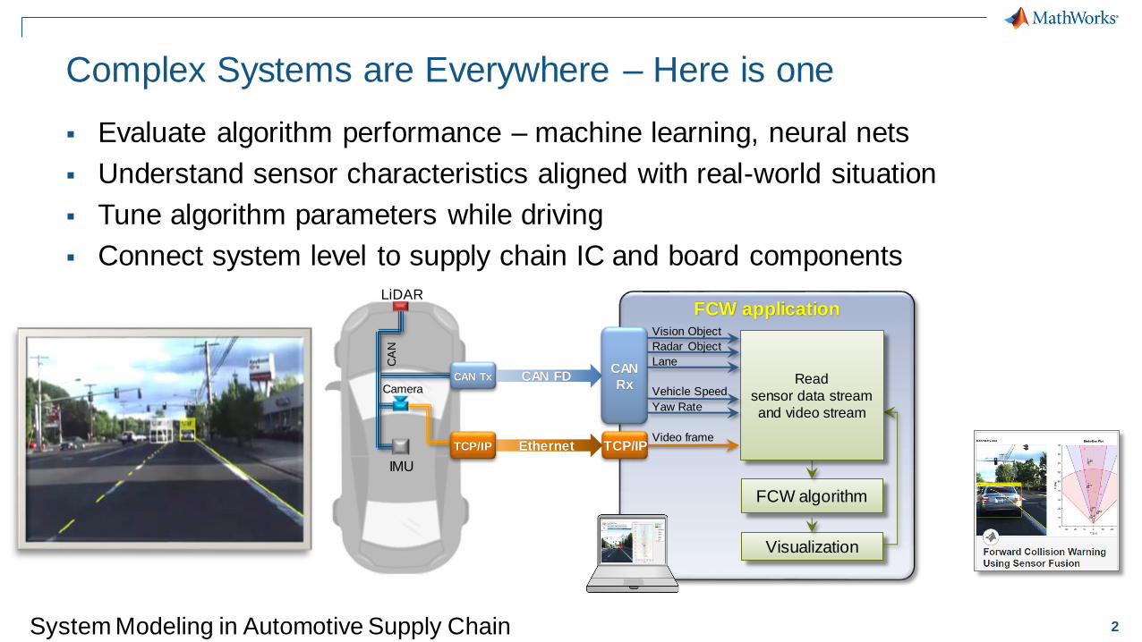
Complex Systems are Everywhere – Here is one
▪ Evaluate algorithm performance – machine learning, neural nets
▪ Understand sensor characteristics aligned with real-world situation
▪ Tune algorithm parameters while driving
▪ Connect system level to supply chain IC and board components
FCW applicationLiDAR
Camera
IMU
CA
N
CAN Tx CAN FD
EthernetTCP/IP
FCW algorithm
Visualization
Read
sensor data stream
and video stream
CAN
Rx
TCP/IP
Vision Object
Radar Object
Lane
Vehicle Speed
Yaw Rate
Video frame
Automated Driving
System Toolbox
System Modeling in Automotive Supply Chain

3
How to tame complexity?
LiDAR Tranceiver Motor Drive Control
Prototype
On FPGA?
Volume
Production
On ASIC?
Prototype
On
Board?
Volume
Production
On SOM?
Embedded
Software?

4
VERIFICATION / INTEGRATION / PROTOTYPE
Top-Down Design With MATLAB and SimulinkFocus on Simulation and Model Refinement at the System Level
Rapid design
construction
Easier analog
modeling
SPECIFICATIONS
IMPLEMENTATION
Spice-likeVHDL, Verilog
AMS IC Tools, Board Tools
Multi-domain
simulation
Fast simulation
Fixed-point and
bit-accurate
simulation
Hardware /
Software
codesign

5
Options to Integrate Workflow with Downstream IC and PCB Tools
• Cosimulation
Option 1
• Code Generation
Option 2
• Post-Processing
Option 3

6
Option 1: Cosimulation
▪ Verify the transistor implementation against the executable specifications
INTEGRATION
IMPLEMENTATION
DESIGN
TE
ST
& V
ER
IFIC
AT
ION
FPGA ASIC
VHDL, Verilog
ASIC SMPS
Spice-like
Algorithms
AnalogDigital
PhysicalFixed-Point
SPECIFICATION

7
Option 2: DPI-C Compliant System Verilog Generation
1. Make the Simulink model / MATLAB code compliant with C code generation
2. Generate C code
3. Automatically wrap the C code using the DPI-C interface
4. Import, build and simulate an equivalent behavioral SystemVerilog model in your IC design tool
2. SystemVerilog wrapper
1. C Code3. IC Design Tool

8
Option 3: Simulation Data Post Processing in MATLAB
Standard design input methods including the creation of
design tests inside Virtuoso ADE Explorer/Assembler/Verifier. These tests can include MATLAB expressions or make calls to MATLAB scripts for post-processing.
MATLAB can read and produce the PSF XL database for ADE
and ViVA. MATLAB can be launched in a real time mode from within ADE for on the fly data-processing.
Virtuoso
Schematic Editor
Virtuoso
ADE Explorer/
Assembler
MATLAB
Virtuoso
Integration With
MATLAB Option
High Performance Data
Processing and Exchange+
Machine Learning
Deep Neural NetsSurrogate ModelingVisualization
OptimizationData Mining

9
Option 3: Workflow Using Neural Net Based Design Optimization
Texas Instruments: “A Surrogate Model Optimization Flow for Analog IC Sizing”

10
Mixed-Signal Example LibraryDownload from: https://www.mathworks.com/campaigns/products/offer/mixed-signal.html

©2018 Cadence Design Systems, Inc. All rights reserved.
• Our software helps engineers move between various stages of electronic design so that your favorite electronic gadget is ready for the holiday rush!
Cadence System Design EnvironmentIntegrating IP, IC, package, PCB, and analysis
Printed Circuit Board (PCB)
Package
Integrated
Circuit (IC)
Intellectual Property (IP)
©2018 Cadence Design Systems, Inc. All rights reserved.
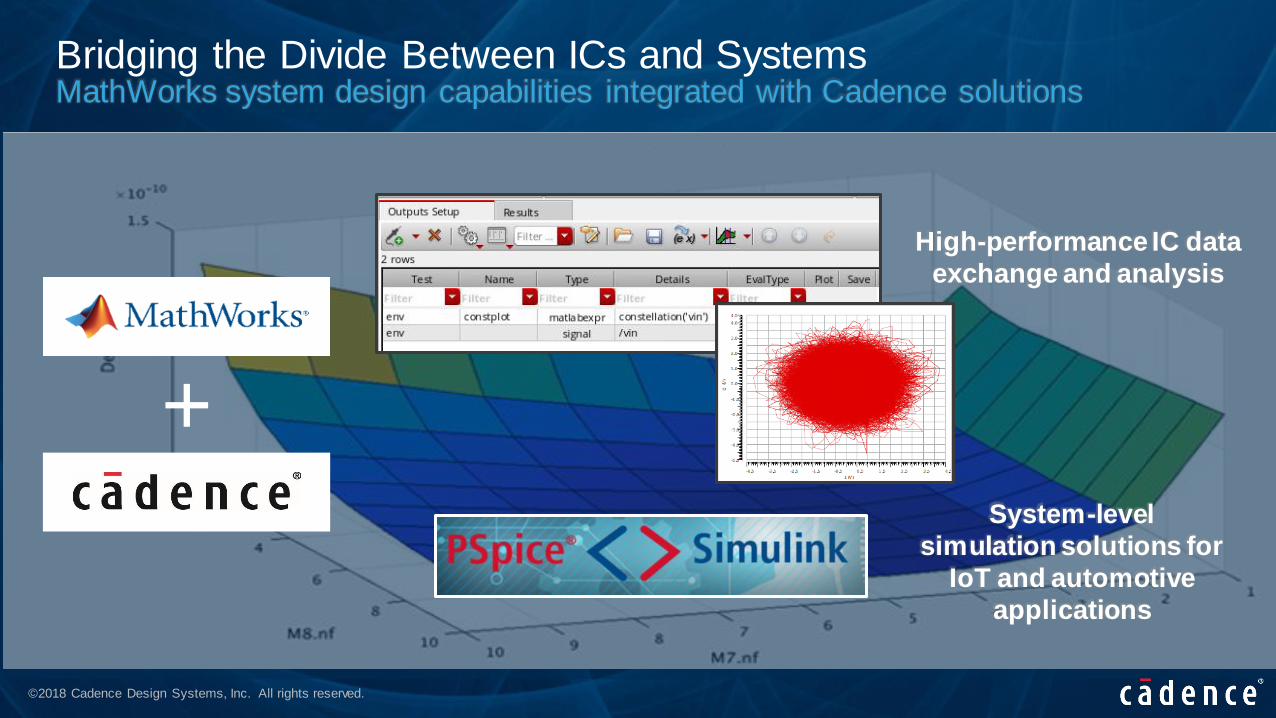
Bridging the Divide Between ICs and SystemsMathWorks system design capabilities integrated with Cadence solutions
+System-level
simulation solutions for
IoT and automotive
applications
High-performance IC data
exchange and analysis
©2018 Cadence Design Systems, Inc. All rights reserved.
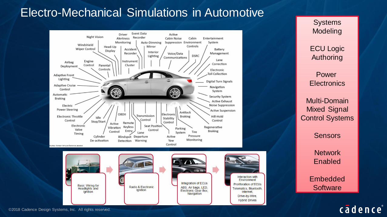
Systems
Modeling
ECU Logic
Authoring
Power
Electronics
Multi-DomainMixed Signal
Control Systems
Sensors
Network
Enabled
Embedded
Software
Electro-Mechanical Simulations in Automotive

©2018 Cadence Design Systems, Inc. All rights reserved.
Easily Integrate MATLAB Models for Mechanical Components
• Eases process of modeling Physical Systems
– Build models that reflect structure of physical system
– Leverage MATLAB to create reusable models
• An electrohydraulic servo-valve example
– Shows multidomain modeling, with electrical, mechanical, and hydraulic components
V+
V-
BPA TT

©2018 Cadence Design Systems, Inc. All rights reserved.
• Field-Oriented Control of a PMSM Drive
• Commonly used in hybrid electric vehicles, manufacturing machinery, and
industrial automation
Permanent Magnet Synchronous Motor Drives
Analog/Mixed-Signal Design
Digital Analog Electro-mechanical
Field-Oriented
ControllerPWM
Power
InverterPMSM
LoadI
v
vexp

©2018 Cadence Design Systems, Inc. All rights reserved.
• From actuators toelectric vehiclemotors
• Acceleration of 0-60mph in 2.7 secs
• Example control of a permanent-magnet-synchrone-machine for motor powertrains
Automotive System Design for Electric VehiclesMATLAB / Simulink / PSpice integration
Digital / Firmware Analog Electro-Mechanical
Field-Oriented
ControllerPWM
Power
InverterPMSM
LoadIv
vexp
Load and Vibration Co-Simulation

©2018 Cadence Design Systems, Inc. All rights reserved.
Model-Based Design for PCB
• Top-Down Workflow
– Starting point:
– Mathematical Model
– Physical Model
– Needs
– Simulation speed (proof of concept)
– Reuse of existing testbench
– Sign-off Transistor-level simulation
– Solution
– Co-simulation with Simulink and PSpice using PSpice Systems Option
– Model integration through automatic C code generation and PSpice DMI
INTEGRATION
IMPLEMENTATION
TE
ST
& V
ER
IFIC
AT
ION
SPICE
SiliconMCU DSPFPGA ASICTEST
SYSTEM
HDL SPICE
DESIGN
REQUIREMENTS
Environment Models
Timing and Control Logic
Digital Models Analog Models
Algorithms
RESEARCH
Timing and Control Logic
Algorithms
Digital Models Analog Models
C/C++C/C++

©2018 Cadence Design Systems, Inc. All rights reserved.
PSpice Simulink Co-Simulation - Benefits
• Co-simulate electrical, mechanical, and systems
• Simulate with ideal models for faster simulation
• Simulate with actual electrical designs using PSpice models
• Electrical simulations with PSpice models exhibit non-linearities, delay, andother real-world effects
• Full access to PSpice and MATLAB environments for in-depth design anddebugging and visualizing data
MATLAB & Simulink

©2018 Cadence Design Systems, Inc. All rights reserved.
PSpice Systems Option
PSpice
Systems
Option
Evaluate
MATLAB®
functions in PSpice
PSpice-MATLAB®
Visualization
Interface
MATLAB ®
Simulink – PSpice
co-simulation
interface.
Import MATLAB
module as
simulation model in
PSpice using
PSpice DMI

©2018 Cadence Design Systems, Inc. All rights reserved.
Examples: PSpice – MATLAB Visualization Interface
• DC Sweep at Multiple Temperature
• Plot multiple B-H loops • Polar Plots on AC Analysis

©2018 Cadence Design Systems, Inc. All rights reserved.
PSpice Systems Option
PSpice
Systems
Option
Evaluate
MATLAB®
functions in PSpice
PSpice-MATLAB®
Visualization
Interface
MATLAB ®
Simulink – PSpice
co-simulation
interface.
Import MATLAB
module as
simulation model in
PSpice using
PSpice DMI

©2018 Cadence Design Systems, Inc. All rights reserved.
Evaluate MATLAB functions in PSpice
Include MATLAB functions for measurements Use MATLAB functions in simulation

©2018 Cadence Design Systems, Inc. All rights reserved.
PSpice Systems Option
PSpice
Systems
Option
Evaluate
MATLAB®
functions in PSpice
PSpice-MATLAB®
Visualization
Interface
MATLAB ®
Simulink – PSpice
co-simulation
interface.
Import MATLAB
module as
simulation model in
PSpice using
PSpice DMI

©2018 Cadence Design Systems, Inc. All rights reserved.
PSpice Simulink Co-Simulation– High Level User Flow
Initial block level
implementation in
Simulink
Implement circuit
level design
with PSpice
Integrate Block and
Circuit level
together using
PSpice CoSim
Fine tune design for
various operating
conditions
1
2
3
4
1
2
3
4

©2018 Cadence Design Systems, Inc. All rights reserved.
PSpice Systems Option
PSpice
Systems
Option
Evaluate
MATLAB®
functions in PSpice
PSpice-MATLAB®
Visualization
Interface
MATLAB ®
Simulink – PSpice
co-simulation
interface.
Import MATLAB
module as
simulation model in
PSpice using
PSpice DMI

©2018 Cadence Design Systems, Inc. All rights reserved.
Import MATLAB module as simulation model in PSpice

©2018 Cadence Design Systems, Inc. All rights reserved.
Summary
• Cadence and MathWorks:
– Provide powerful tools to mine information and visualize results from
simulation data
– Allow you to “shift left” and make correct architecture decisions and reduce
long, costly design iterations
– Enable you to bring system-level considerations into your IC and PCB design
and verification flows
• Next Steps:
– Come visit Cadence Booth in the MATLAB Expo Exhibition area

©2018 Cadence Design Systems, Inc. All rights reserved.
Contacts
• MathWorks Contact:
– Rajesh Berigei [email protected]
• Cadence Contacts :
– Kishore Karnane [email protected]
– Steve Lewis [email protected]
©2018 Cadence Design Systems, Inc. All rights reserved.
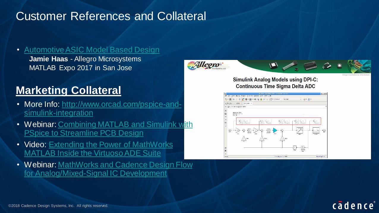
Customer References and Collateral
• Automotive ASIC Model Based DesignJamie Haas - Allegro Microsystems
MATLAB Expo 2017 in San Jose
• More Info: http://www.orcad.com/pspice-and-simulink-integration
• Webinar: Combining MATLAB and Simulink with PSpice to Streamline PCB Design
• Video: Extending the Power of MathWorks MATLAB Inside the Virtuoso ADE Suite
• Webinar: MathWorks and Cadence Design Flow for Analog/Mixed-Signal IC Development
Marketing Collateral

©2018 Cadence Design Systems, Inc. All rights reserved.
© 2018 Cadence Design Systems, Inc. All rights reserved worldwide. Cadence, the Cadence logo, and the other Cadence marks found at www.cadence.com/go/trademarks are trademarks or registered trademarks ofCadence Design Systems, Inc. All other trademarks are the property of their respective owners.


