Constructional Project LF and VLF Converter Raymond Haigh Simple practical circuits for exploring the lower reaches of the electromagnetic spectrum F OLLOWING on from the popular series on Practical Radio Circuits (June ’03 to Jan ’05), a number of readers have asked for a further article dealing specifically with reception on low (LF) and very low frequencies (VLF). This additional material has been prepared in response to their request and, as before, the emphasis is on practical circuits for experimenters. The simple converter unit outlined here will allow a high performance receiver to tune into transmission from below 10kHz to 350kHz. Also, alternative aerial systems are described. What’s There? Britain, Ireland, France, Germany and Russia, operate high-power broadcast transmitters in what is known as the long- wave band, covering 150kHz to 350kHz. An amateur band is centred on 136kHz and various other transmissions are radiat- ed from 150kHz to below 10kHz. In the 1kHz to 20kHz region whistlers or howlers can be found – these are a natural electromagnetic phenomenon caused by distant lightning. Longwave broadcasting did not take hold outside Europe. In the Americas, Canada, Australia and New Zealand, fre- quencies below 550kHz are allocated for time signals, military, government and commercial data, and marker beacons used primarily by the aviation industry. As the frequency is lowered, electromag- netic waves penetrate water and earth to an increasing depth. Frequencies below 10kHz are used by the military for commu- nicating with submarines. On a more peaceful note, localized communications with cavers or potholers are achieved on a frequency of 874Hz (the Molefone). Whistlers Natural electromagnetic phenomena, known as whistlers or howlers, occur at frequencies between 1kHz and 20kHz. Electromagnetic waves, caused by dis- tant lightning, are distorted as they trav- el around the earth, and this produces a whistling or howling sound at the receiver. Greatest activity is usually dur- ing the summer months, between sunset and dawn. Whistler receivers are no more than sen- sitive audio amplifiers connected to a short aerial. They incorporate filtering to exclude higher radio frequencies, and to curtail the response of the amplifier to mains hum and its harmonics. Despite these measures, whistler receivers must be battery powered and operated some distance from mains wiring and power lines. Listening In Receiving signals radiated at low (LF) and very low frequencies (VLF) presents no major difficulties, and the add-on circuits described here will extend the coverage of the two high performance receiver designs, Regenerative and Superhet, included in the Practical Radio Circuits series. Serious listeners often use commercial communications receivers, again with add-on units to extend coverage and/or improve per- formance. The circuits presented in this article are equally suitable for equipment of this kind. The tuning circuits must, of course, con- tain much more inductance and capacitance to resonate at the lower frequencies. Wire aerials, even when physically quite long, are only a small fraction of a wavelength. Because of this, they terminate at a high impedance which needs to be matched to the receiver. Man-made and natural electrical distur- bances result in comparatively high noise levels at low frequencies. The problem is inevitably worse in urban areas, and is often the limiting factor in resolving very weak signals. Converter Unit Some communications receivers can be tuned to the lowest reaches of the spectrum, but most end their coverage at or above 100kHz. Many incorporate broadband input filters, and performance deteriorates at low frequencies. Even if the receiver has fully variable front end tuning, there is 478 Everyday Practical Electronics, July 2005 The three circuit boards that make up the LF and VLF Converter Unit. From left to right: variable tuner, fixed/switched tuner, and mixer/oscillator
Transcript
Constructional Project
LF and VLF Converter
RRaayymmoonndd HHaaiigghh
Simple practical circuits for exploring the lower reaches of the
electromagnetic spectrum
FOLLOWING on from the popularseries on Practical Radio Circuits(June ’03 to Jan ’05), a number of
readers have asked for a further articledealing specifically with reception on low(LF) and very low frequencies (VLF).This additional material has been preparedin response to their request and, as before,the emphasis is on practical circuits forexperimenters.
The simple converter unit outlined herewill allow a high performance receiver totune into transmission from below 10kHzto 350kHz. Also, alternative aerial systemsare described.
What’s There? Britain, Ireland, France, Germany and
Russia, operate high-power broadcasttransmitters in what is known as the long-wave band, covering 150kHz to 350kHz.An amateur band is centred on 136kHzand various other transmissions are radiat-ed from 150kHz to below 10kHz. In the1kHz to 20kHz region whistlers orhowlers can be found – these are a naturalelectromagnetic phenomenon caused bydistant lightning.
Longwave broadcasting did not takehold outside Europe. In the Americas,Canada, Australia and New Zealand, fre-quencies below 550kHz are allocated fortime signals, military, government andcommercial data, and marker beacons usedprimarily by the aviation industry.
As the frequency is lowered, electromag-netic waves penetrate water and earth to anincreasing depth. Frequencies below10kHz are used by the military for commu-nicating with submarines. On a morepeaceful note, localized communicationswith cavers or potholers are achieved on afrequency of 874Hz (the Molefone).
Whistlers Natural electromagnetic phenomena,
known as whistlers or howlers, occur atfrequencies between 1kHz and 20kHz.Electromagnetic waves, caused by dis-tant lightning, are distorted as they trav-el around the earth, and this produces awhistling or howling sound at thereceiver. Greatest activity is usually dur-ing the summer months, between sunsetand dawn.
Whistler receivers are no more than sen-sitive audio amplifiers connected to a shortaerial. They incorporate filtering to excludehigher radio frequencies, and to curtail theresponse of the amplifier to mains hum andits harmonics. Despite these measures,whistler receivers must be battery poweredand operated some distance from mainswiring and power lines.
Listening InReceiving signals radiated at low (LF)
and very low frequencies (VLF) presents nomajor difficulties, and the add-on circuitsdescribed here will extend the coverage ofthe two high performance receiver designs,Regenerative and Superhet, included in thePractical Radio Circuits series.
Serious listeners often use commercialcommunications receivers, again with add-onunits to extend coverage and/or improve per-formance. The circuits presented in this articleare equally suitable for equipment of this kind.
The tuning circuits must, of course, con-tain much more inductance and capacitanceto resonate at the lower frequencies. Wireaerials, even when physically quite long, areonly a small fraction of a wavelength.Because of this, they terminate at a highimpedance which needs to be matched tothe receiver.
Man-made and natural electrical distur-bances result in comparatively high noiselevels at low frequencies. The problem isinevitably worse in urban areas, and isoften the limiting factor in resolving veryweak signals.
Converter UnitSome communications receivers can be
tuned to the lowest reaches of the spectrum,but most end their coverage at or above100kHz. Many incorporate broadbandinput filters, and performance deterioratesat low frequencies. Even if the receiver hasfully variable front end tuning, there is
478 Everyday Practical Electronics, July 2005
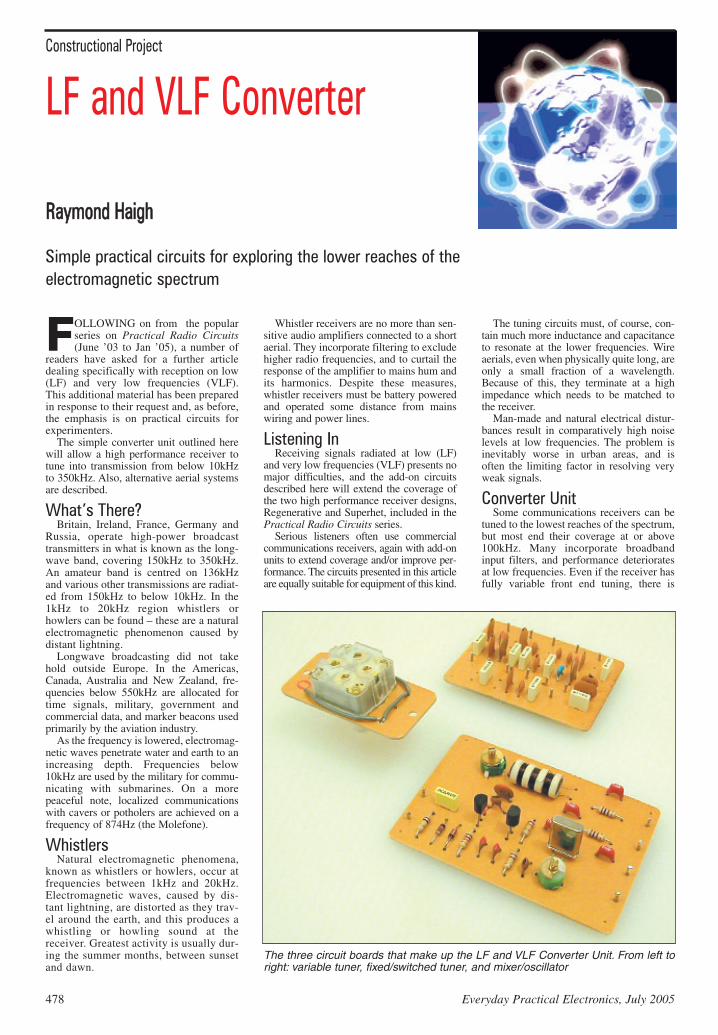
The three circuit boards that make up the LF and VLF Converter Unit. From left toright: variable tuner, fixed/switched tuner, and mixer/oscillator
Positive feedback, from TR2 emitter (e),is injected via capacitors C16 and C18, andresistors R5 and R6 set the bias on the base(b) of TR2. The oscillator output is devel-oped across emitter resistor R3. This com-ponent also acts as the source bias resistorfor transistor TR1, and the local oscillationis thereby injected directly into the mixer.
The stage is decoupled from the supplyrail by resistor R4 and capacitor C15.
I.F. OutputThe tuned circuit formed by coil L1,
trimmer capacitor VC2 and capacitor C13,selects the 4MHz i.f. output (it passes aband of frequencies from 4MHz to4·350MHz, see earlier). Matching to thelow impedance input of the communica-tions receiver is achieved by coil L2, andC17 acts as a d.c. blocking capacitor (somereceivers can have d.c. voltages on theirinput circuitry).
The mixer stage, TR1, is decoupled fromthe supply by resistor R2 and capacitor C14.
Powering UpCurrent drain is very modest, around 4mA
plus the current taken by the optional l.e.d.,D3, On indicator and its ballast resistor, R7.
A PP3 type battery is, therefore, anappropriate and convenient means of pow-ering the Converter. Switch S2 connectspower to the circuit and bypass capacitorC20 ensures stability and consistentoperation as the battery ages.
Everyday Practical Electronics, July 2005 479
often a considerable mismatch to the aerialon longwaves, and signal transfer is lessthan optimum.
A step-up converter, which changes thefrequency of incoming signals to, say,4MHz, overcomes the problem of cover-age. With appropriate input circuits, signallosses due to broad tuning and aerial mis-match can be reduced significantly.
All ChangeFrequency changing, which is funda-
mental to superhet receivers, was cov-ered at length in the “Radio” series(June’03 to Jan’04). In brief, a locallygenerated oscillation is combined withthe incoming signal in a mixer stage, andthe difference between the two, knownas the intermediate frequency, is selectedby a tuned circuit connected to themixer’s output port.
The intermediate frequency (i.f.) isusually fixed, and the receiver tuned byaltering the oscillator frequency andadjusting the input circuits. When only anarrow band of frequencies has to be cov-ered, it is often more convenient to fix theoscillator frequency and tune the systemby varying the intermediate frequencyinstead.
The entire VLF/LF spectrum is locatedwithin a band of frequencies no morethan 350kHz wide, and a single 4MHzi.f. transformer, “damped” by the mixerand the feeder to the receiver, will tunebroadly enough to accommodate it. Theprecise i.f. is varied by sweeping thecommunication receiver’s tuning from4MHz to 4·350MHz, which gives a sig-nal frequency coverage from zero to350kHz.
LF/VLF Converter CircuitThe circuit diagram for the LF/VLF
Converter is shown in Fig.1, where thefixed tuning capacitors, C1 to C11 areselected by rotary switch S1. The switched
increments ofcapacitance aresmaller than themaximum valueof the variabletuning capacitor,VC1, and thea r r a n g e m e n tthus provides ac o n t i n u o u s l yvariable capaci-tance swing ofaround 20pF to 2800pF.
Details of an inductor (coil), which com-pletes the tuned circuit, are given later,together with details of a Loop Aerial.
MixerThe received signal is applied, via d.c.
blocking capacitor C12, to the gate (g) ofthe field-effect transistor mixer stage TR1.High impedance at the gate minimizesdamping on the input tuned circuit.
Diodes D1 and D2 shunt signals inexcess of around 0·6V and protect thetransistor against static damage. (Longwire aerials and high value tuning induc-tors increase the vulnerability of theunit).
The gate (g) of TR1 is connected to the0V rail via resistor R1 in order to ensurecorrect biasing.
OscillatorTransistor TR2 is configured as a
Colpitt’s oscillator. The operating fre-quency is fixed, with a high degree ofaccuracy and stability, by quartz crystalX1.
The crystal is loaded by capacitor C19and trimmer VC3: the latter permits the fre-quency of oscillation to be set at precisely4MHz. Readers who do not require themain receiver’s dial reading to be very pre-cise can delete VC3 (the dial readings willstill be accurate enough for all but the mostdemanding applications).
Fig.1. Full circuit diagram for the LF/VLF Converter. Thecircuit is split in two sections; tuning and mixer/oscillator
Front panel controls of the Converter
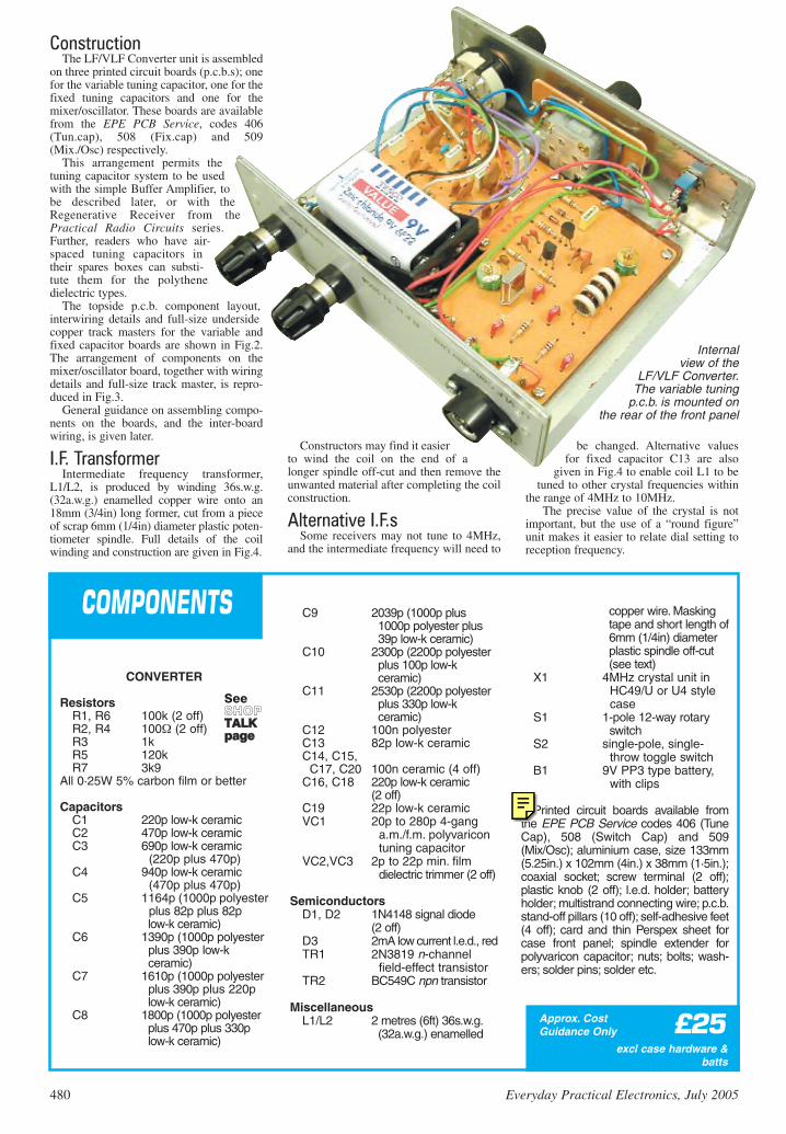
ConstructionThe LF/VLF Converter unit is assembled
on three printed circuit boards (p.c.b.s); onefor the variable tuning capacitor, one for thefixed tuning capacitors and one for themixer/oscillator. These boards are availablefrom the EPE PCB Service, codes 406(Tun.cap), 508 (Fix.cap) and 509(Mix./Osc) respectively.
This arrangement permits thetuning capacitor system to be usedwith the simple Buffer Amplifier, tobe described later, or with theRegenerative Receiver from thePractical Radio Circuits series.Further, readers who have air-spaced tuning capacitors intheir spares boxes can substi-tute them for the polythenedielectric types.
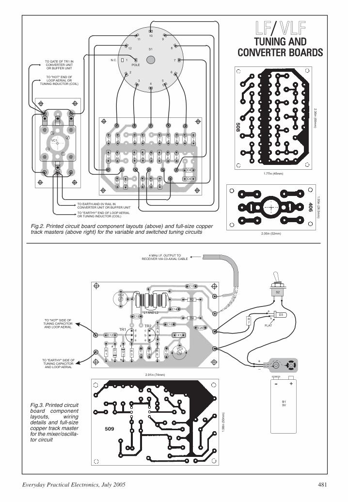
The topside p.c.b. component layout,interwiring details and full-size undersidecopper track masters for the variable andfixed capacitor boards are shown in Fig.2.The arrangement of components on themixer/oscillator board, together with wiringdetails and full-size track master, is repro-duced in Fig.3.
General guidance on assembling compo-nents on the boards, and the inter-boardwiring, is given later.
I.F. TransformerIntermediate frequency transformer,
L1/L2, is produced by winding 36s.w.g.(32a.w.g.) enamelled copper wire onto an18mm (3/4in) long former, cut from a pieceof scrap 6mm (1/4in) diameter plastic poten-tiometer spindle. Full details of the coilwinding and construction are given in Fig.4.
Constructors may find it easierto wind the coil on the end of alonger spindle off-cut and then remove theunwanted material after completing the coilconstruction.
Alternative I.F.sSome receivers may not tune to 4MHz,
and the intermediate frequency will need to
be changed. Alternative valuesfor fixed capacitor C13 are also
given in Fig.4 to enable coil L1 to betuned to other crystal frequencies within
the range of 4MHz to 10MHz.The precise value of the crystal is not
important, but the use of a “round figure”unit makes it easier to relate dial setting toreception frequency.
(2 off)C19 22p low-k ceramicVC1 20p to 280p 4-gang
a.m./f.m. polyvaricon tuning capacitor
VC2,VC3 2p to 22p min. film dielectric trimmer (2 off)
SemiconductorsD1, D2 1N4148 signal diode
(2 off)D3 2mA low current l.e.d., redTR1 2N3819 n-channel
field-effect transistorTR2 BC549C npn transistor
MiscellaneousL1/L2 2 metres (6ft) 36s.w.g.
(32a.w.g.) enamelled
copper wire. Masking tape and short length of 6mm (1/4in) diameter plastic spindle off-cut (see text)
X1 4MHz crystal unit in HC49/U or U4 style case
S1 1-pole 12-way rotary switch
S2 single-pole, single-throw toggle switch
B1 9V PP3 type battery, with clips
Printed circuit boards available fromthe EPE PCB Service codes 406 (TuneCap), 508 (Switch Cap) and 509(Mix/Osc); aluminium case, size 133mm(5.25in.) x 102mm (4in.) x 38mm (1·5in.);coaxial socket; screw terminal (2 off);plastic knob (2 off); l.e.d. holder; batteryholder; multistrand connecting wire; p.c.b.stand-off pillars (10 off); self-adhesive feet(4 off); card and thin Perspex sheet forcase front panel; spindle extender forpolyvaricon capacitor; nuts; bolts; wash-ers; solder pins; solder etc.
SeeSSHHOOPPTTAALLKKppaaggee
480 Everyday Practical Electronics, July 2005
EPE-Online
Note that the circuit boards used in EPE Online projects are available from the EPE Online Store at www.epemag.com (also note that the codes for the boards in the online store are prefixed with 7000, so a board with a code of say 256 will appear as 7000256 in the online store).
Fig.2. Printed circuit board component layouts (above) and full-size coppertrack masters (above right) for the variable and switched tuning circuits
LLFF/ VVLLFFTTUUNNIINNGG AANNDD
CCOONNVVEERRTTEERR BBOOAARRDDSS
Everyday Practical Electronics, July 2005 481
Fig.3. Printed circuitboard componentlayouts, wiringdetails and full-sizecopper track masterfor the mixer/oscilla-tor circuit
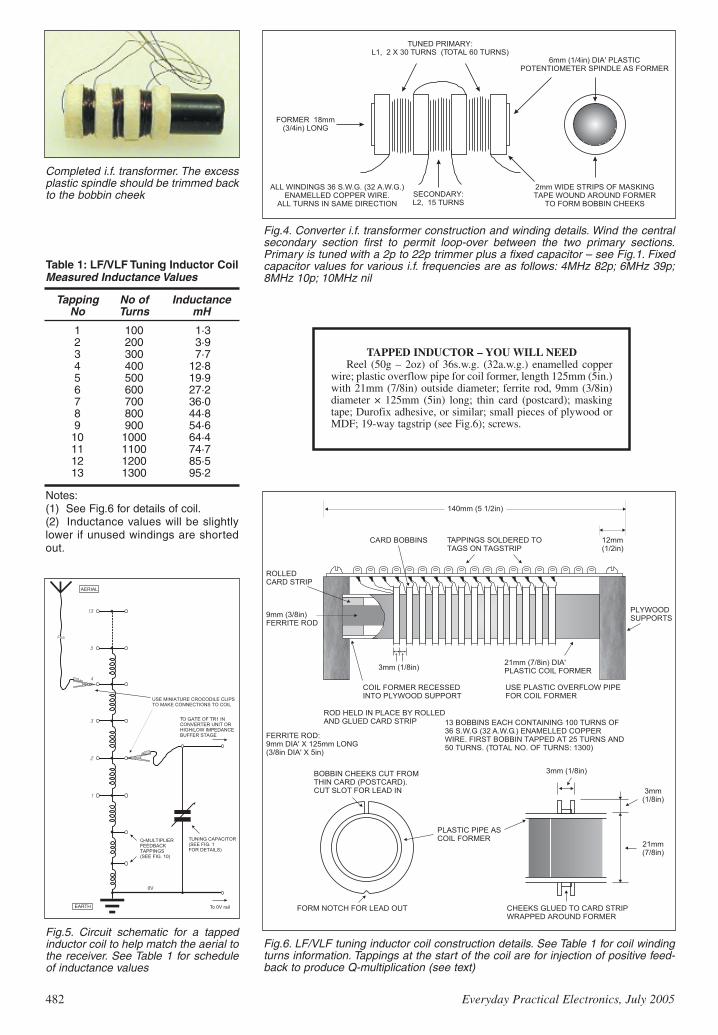
Completed i.f. transformer. The excessplastic spindle should be trimmed backto the bobbin cheek
Fig.4. Converter i.f. transformer construction and winding details. Wind the centralsecondary section first to permit loop-over between the two primary sections.Primary is tuned with a 2p to 22p trimmer plus a fixed capacitor – see Fig.1. Fixedcapacitor values for various i.f. frequencies are as follows: 4MHz 82p; 6MHz 39p;8MHz 10p; 10MHz nil
Fig.6. LF/VLF tuning inductor coil construction details. See Table 1 for coil windingturns information. Tappings at the start of the coil are for injection of positive feed-back to produce Q-multiplication (see text)
TAPPED INDUCTOR – YOU WILL NEEDReel (50g – 2oz) of 36s.w.g. (32a.w.g.) enamelled copper
wire; plastic overflow pipe for coil former, length 125mm (5in.)with 21mm (7/8in) outside diameter; ferrite rod, 9mm (3/8in)diameter × 125mm (5in) long; thin card (postcard); maskingtape; Durofix adhesive, or similar; small pieces of plywood orMDF; 19-way tagstrip (see Fig.6); screws.
Fig.5. Circuit schematic for a tappedinductor coil to help match the aerial tothe receiver. See Table 1 for scheduleof inductance values
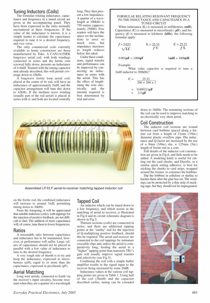
itance and frequency in a tuned circuit aregiven in the accompanying panel. Theyhave been expressed in the units normallyencountered at these frequencies. If thevalue of the inductance is known, it is asimple matter to calculate the capacitancerequired to tune it to a desired frequency,and vice versa.
The only commercial coils currentlyavailable to home constructors are thosemanufactured by Toko. A CAN1A350EKlongwave aerial coil, with both windingsconnected in series and the ferrite corescrewed fully down, presents an inductanceof 4·4mH. Teamed with the tuning capacitorunit already described, this will permit cov-erage down to 45kHz.
A longwave ferrite loop aerial coil,placed at the centre of its rod, will have aninductance of approximately 5mH, and thecapacitor arrangement will tune this downto 42kHz. If the medium wave winding(usually part of the rod aerial) is placed inseries with it, and both are located centrally
on the ferrite rod, the combined inductancewill increase to around 7mH, permittingtuning down to 36kHz.
From the foregoing, it will be appreciatedthat suitable inductors (coils), with tappings forthe injection of positive feedback, are not diffi-cult to find. The addition of more capacitancewill, of course, tune them to lower frequencies.
Ratios A reasonable ratio between capacitance
and inductance has to be maintained, how-ever, or performance will suffer. Large val-ues of capacitance should not be placed inparallel with a low value of inductance totune to the desired frequency.
A very rough rule of thumb is to try andkeep the inductance, expressed in micro-henries (µH), equal to or more than thecapacitance, expressed in picofarads (pF).
Aerial MatchingLong wire aerials, connected to Earth via
the receiver’s input circuitry, become reso-nant when they are a quarter of a wavelength
long. They then pres-ent a low impedance.A quarter of a wave-length at 100kHz is750 metres (approxi-mately 2500ft). Fewreaders will have thespace (or the inclina-tion) to erect somuch wire, butimpedance increasesas length reducesbelow this ideal.
Under these condi-tions, signal transferand performance canbe improved by con-necting an induc-tance in series withthe aerial. This hasthe effect of length-ening the wire elec-trically, and theamount required isbest determined bytrial and error.
Tapped CoilAn inductor which can be tuned down to
a low frequency, and which assists in thematching of aerial to receiver, is illustratedin Fig.6 and its circuit schematic diagram isshown in Fig.5.
Thirteen sections (coils) are connected inseries, and there are additional tappingpoints at the “earthy” end for the injectionof Q-multiplying positive feedback, shouldthis be required. The aerial and receiver areconnected to the coil tappings by miniaturecrocodile clips and, unless the aerial is com-paratively long, feeding the aerial to a“higher” tapping point than transistor TR1’sgate will usually improve signal transferand selectivity (see Fig.5).
Combining the coil with a simple bufferamplifier results in the signal input to thereceiver being increased by some 20dB.
Inductance values at the various coil tap-ping points are given in Table 1. Using halfof the coil (36mH) and the capacitordescribed earlier, tuning can be extended
down to 16kHz. The remaining sections ofthe coil can be used to improve matching toan electrically very short aerial.
Coil ConstructionThe inductor coil sections are wound
between card bobbins spaced along a for-mer cut from a length of 21mm (7/8in.)diameter plastic overflow pipe. The induc-tance and Q-factor are increased by the useof a 9mm (3/8in.) dia. × 125mm (5in.)length of ferrite rod as a core.
Full details of the inductor coil construc-tion are given in Fig.6, and little needs to beadded. A modeling knife is useful for cut-ting out the card cheeks, and Durofix, or asimilar quick setting adhesive, is best forsticking the cheeks to card strips, wrappedaround the former, to construct the bobbins.
Dip the bobbins in cellulose or shellac toharden them after the glue has set. The wind-ings can be protected by a thin strip of mask-ing tape, but they should not be impregnated.
FORMULAE RELATING RESONANT FREQUENCYTO THE INDUCTANCE AND CAPACITANCE IN A
TUNED CIRCUITWhen inductance (L) is measured in millihenries (mH),
Capacitance (C) is measured in microfarads ( µµF), and fre-quency (f) is measured in kilohertz (kHz), the followingformulae apply:
0·001µµF = 1000pF 1mH = 1000µµH
Example:What value capacitor is required to tune a
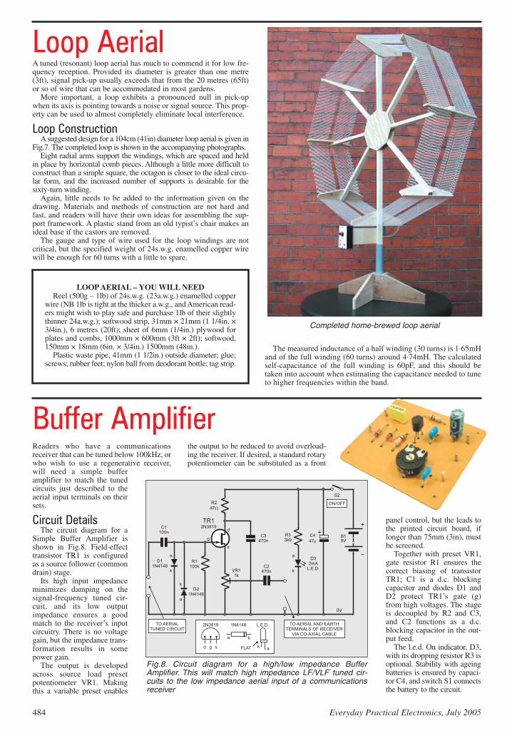
Loop AerialA tuned (resonant) loop aerial has much to commend it for low fre-quency reception. Provided its diameter is greater than one metre(3ft), signal pick-up usually exceeds that from the 20 metres (65ft)or so of wire that can be accommodated in most gardens.
More important, a loop exhibits a pronounced null in pick-upwhen its axis is pointing towards a noise or signal source. This prop-erty can be used to almost completely eliminate local interference.
Loop Construction Asuggested design for a 104cm (41in) diameter loop aerial is given in
Fig.7. The completed loop is shown in the accompanying photographs. Eight radial arms support the windings, which are spaced and held
in place by horizontal comb pieces. Although a little more difficult toconstruct than a simple square, the octagon is closer to the ideal circu-lar form, and the increased number of supports is desirable for thesixty-turn winding.
Again, little needs to be added to the information given on thedrawing. Materials and methods of construction are not hard andfast, and readers will have their own ideas for assembling the sup-port framework. A plastic stand from an old typist’s chair makes anideal base if the castors are removed.
The gauge and type of wire used for the loop windings are notcritical, but the specified weight of 24s.w.g. enamelled copper wirewill be enough for 60 turns with a little to spare.
The measured inductance of a half winding (30 turns) is 1·65mHand of the full winding (60 turns) around 4·74mH. The calculatedself-capacitance of the full winding is 60pF, and this should betaken into account when estimating the capacitance needed to tuneto higher frequencies within the band.
Completed home-brewed loop aerial
Readers who have a communicationsreceiver that can be tuned below 100kHz, orwho wish to use a regenerative receiver,will need a simple bufferamplifier to match the tunedcircuits just described to theaerial input terminals on theirsets.
Circuit DetailsThe circuit diagram for a
Simple Buffer Amplifier isshown in Fig.8. Field-effecttransistor TR1 is configuredas a source follower (commondrain) stage.
Its high input impedanceminimizes damping on thesignal-frequency tuned cir-cuit, and its low outputimpedance ensures a goodmatch to the receiver’s inputcircuitry. There is no voltagegain, but the impedance trans-formation results in somepower gain.
The output is developedacross source load presetpotentiometer VR1. Makingthis a variable preset enables
the output to be reduced to avoid overload-ing the receiver. If desired, a standard rotarypotentiometer can be substituted as a front
panel control, but the leads tothe printed circuit board, iflonger than 75mm (3in), mustbe screened.
Together with preset VR1,gate resistor R1 ensures thecorrect biasing of transistorTR1; C1 is a d.c. blockingcapacitor and diodes D1 andD2 protect TR1’s gate (g)from high voltages. The stageis decoupled by R2 and C3,and C2 functions as a d.c.blocking capacitor in the out-put feed.
The l.e.d. On indicator, D3,with its dropping resistor R3 isoptional. Stability with ageingbatteries is ensured by capaci-tor C4, and switch S1 connectsthe battery to the circuit.
LOOP AERIAL – YOU WILL NEEDReel (500g – 1lb) of 24s.w.g. (23a.w.g.) enamelled copper
wire (NB 1lb is tight at the thicker a.w.g., and American read-ers might wish to play safe and purchase 1lb of their slightlythinner 24a.w.g.); softwood strip, 31mm × 21mm (1 1/4in. ×3/4in.), 6 metres (20ft); sheet of 6mm (1/4in.) plywood forplates and combs, 1000mm × 600mm (3ft × 2ft); softwood,150mm × 18mm (6in. × 3/4in.) 1500mm (48in.).
Plastic waste pipe, 41mm (1 1/2in.) outside diameter; glue;screws; rubber feet; nylon ball from deodorant bottle; tag strip.
Buffer Amplifier
Fig.8. Circuit diagram for a high/low impedance BufferAmplifier. This will match high impedance LF/VLF tuned cir-cuits to the low impedance aerial input of a communicationsreceiver
484 Everyday Practical Electronics, July 2005
Fig.7. Constructional details for an LF/VLF Loop Aerial withoptimal Q-Multiplier. Eight radial arms support the 24s.w.g.
enamelled copper wire windings
Everyday Practical Electronics, July 2005 485
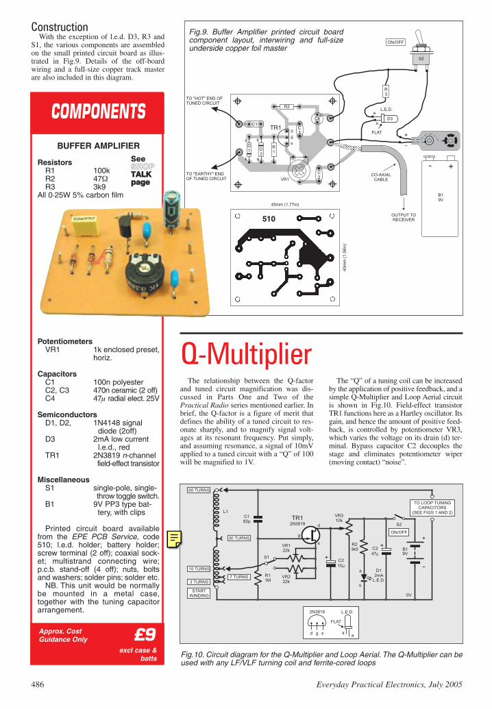
ConstructionWith the exception of l.e.d. D3, R3 and
S1, the various components are assembledon the small printed circuit board as illus-trated in Fig.9. Details of the off-boardwiring and a full-size copper track masterare also included in this diagram.
The relationship between the Q-factorand tuned circuit magnification was dis-cussed in Parts One and Two of thePractical Radio series mentioned earlier. Inbrief, the Q-factor is a figure of merit thatdefines the ability of a tuned circuit to res-onate sharply, and to magnify signal volt-ages at its resonant frequency. Put simply,and assuming resonance, a signal of 10mVapplied to a tuned circuit with a “Q” of 100will be magnified to 1V.
The “Q” of a tuning coil can be increasedby the application of positive feedback, and asimple Q-Multiplier and Loop Aerial circuitis shown in Fig.10. Field-effect transistorTR1 functions here as a Hartley oscillator. Itsgain, and hence the amount of positive feed-back, is controlled by potentiometer VR3,which varies the voltage on its drain (d) ter-minal. Bypass capacitor C2 decouples thestage and eliminates potentiometer wiper(moving contact) “noise”.
NB. This unit would be normallybe mounted in a metal case,together with the tuning capacitorarrangement.
SeeSSHHOOPPTTAALLKKppaaggee
Q-Multiplier
Fig.10. Circuit diagram for the Q-Multiplier and Loop Aerial. The Q-Multiplier can beused with any LF/VLF turning coil and ferrite-cored loops
486 Everyday Practical Electronics, July 2005
EPE-Online
Note that the circuit boards used in EPE Online projects are available from the EPE Online Store at www.epemag.com (also note that the codes for the boards in the online store are prefixed with 7000, so a board with a code of say 256 will appear as 7000256 in the online store).
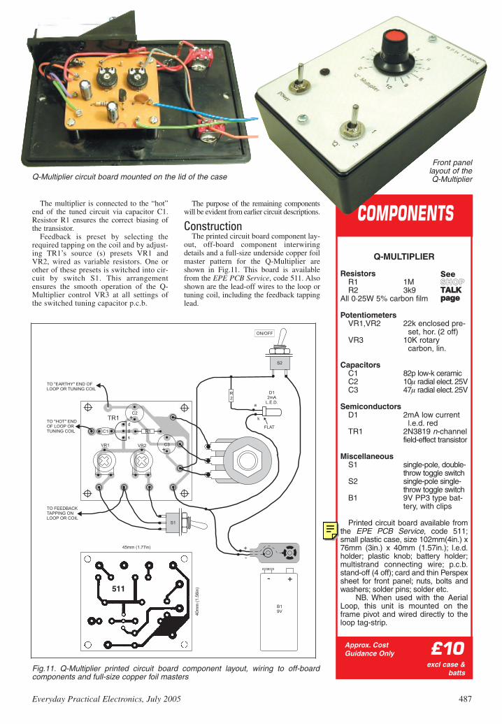
The multiplier is connected to the “hot”end of the tuned circuit via capacitor C1.Resistor R1 ensures the correct biasing ofthe transistor.
Feedback is preset by selecting therequired tapping on the coil and by adjust-ing TR1’s source (s) presets VR1 andVR2, wired as variable resistors. One orother of these presets is switched into cir-cuit by switch S1. This arrangementensures the smooth operation of the Q-Multiplier control VR3 at all settings ofthe switched tuning capacitor p.c.b.
The purpose of the remaining componentswill be evident from earlier circuit descriptions.
out, off-board component interwiringdetails and a full-size underside copper foilmaster pattern for the Q-Multiplier areshown in Fig.11. This board is availablefrom the EPE PCB Service, code 511. Alsoshown are the lead-off wires to the loop ortuning coil, including the feedback tappinglead.
Fig.11. Q-Multiplier printed circuit board component layout, wiring to off-boardcomponents and full-size copper foil masters
511
Q-Multiplier circuit board mounted on the lid of the case
Printed circuit board available fromthe EPE PCB Service, code 511;small plastic case, size 102mm(4in.) x76mm (3in.) x 40mm (1.57in.); l.e.d.holder; plastic knob; battery holder;multistrand connecting wire; p.c.b.stand-off (4 off); card and thin Perspexsheet for front panel; nuts, bolts andwashers; solder pins; solder etc.
NB. When used with the AerialLoop, this unit is mounted on theframe pivot and wired directly to theloop tag-strip.
SeeSSHHOOPPTTAALLKKppaaggee
COMPONENTS
Everyday Practical Electronics, July 2005 487
Front panel layout of the Q-Multiplier
EPE-Online
Note that the circuit boards used in EPE Online projects are available from the EPE Online Store at www.epemag.com (also note that the codes for the boards in the online store are prefixed with 7000, so a board with a code of say 256 will appear as 7000256 in the online store).
ComponentsAlmost any n-channel junction field-
effect transistor should be suitable for thesecircuits. But check base connections assome are bound to vary. Similarly, almostany small-signal npn bipolar transistorshould function as the oscillator, TR2, in theConverter unit. However, reliable oscilla-tion and a decent input to the mixer will beensured by the use a device with good hfe
and fT figures, especially if the i.f. frequen-cy is increased to 10MHz.
Close tolerance polystyrene capacitorsare the preferred components for theswitched tuning system. High value exam-ples are, however, expensive and bulky.With this in mind, low-k ceramic capacitorshave been specified for values up to 470pF,and polyester components for the 1nF and2·2nF units. Do not use high value ceramiccapacitors. Their “Q” factor and stabilitycan be low, and they are unsuitable for usein tuned circuits.
All four sections of an a.m./f.m. poly-varicon tuning capacitor are connectedtogether to produce the 20pF to 280pFcapacitance swing required for the variabletuning element. Most small polyvariconswill have maximum capacitance values ofthis order, and some greater.
AssemblyAlmost all of the components for the LF
and VLF Converter are mounted on smallprinted circuit boards. Solder pins, insertedat the lead-out points, will simplify off-board wiring, and they should be insertedinto the board first.
When populating the Converter p.c.b.,mount the i.f. transformer, L1/L2, next,after inserting the solder pins. It can besecured to the board by a drop of Superglue(cyanoacrylate adhesive).
Follow this with the resistors, then thecapacitors, smallest first. The semiconduc-tors and the crystal should be soldered ontothe board last in order to avoid the repeatedheating of these components. It is goodpractice to use a miniature crocodile clip asa heat shunt when mounting the field-effecttransistor.
The optional l.e.d. On indicators, andtheir dropping resistors, are wired betweenthe On/Off switch and/or the appropriatepins on the boards.
Setting Up and TestingCheck all the printed circuit boards for
poor soldered joints and bridged tracks.Double-check the placement of componentson the p.c.b.s and the orientation of semi-conductors and electrolytic capacitors. If allis in order, proceed as follows:
Converter Unit Starting with the Converter Unit, connect
a fresh 9V battery. Current consumptionshould be approximately 4mA (excludingthe current drawn by any l.e.d. indicator).
Connect the unit to the Receiver via ashort (no more than 1 metre or 3ft) length ofcoaxial cable and set the dial of the receiverto 4MHz (4000kHz) plus the frequency ofsome powerful longwave transmitter. BBCRadio 4 on 198kHz is ideal in many parts ofthe UK, and this would require a receiverdial reading of 4198kHz.
Connect an aerial to capacitor C12 (theinput is not tuned for this initial test). The
chosen station should now beheard. Adjust the i.f. transformertuning capacitor VC2 for highestreading on the receiver’s signalstrength meter.
Note that provision is made, onthe p.c.b., for the insertion of anadditional fixed capacitor in orderto refine the tuning of coil L1. Ifthe coil is constructed as specified,it should come to resonance withtrimmer VC2 at about mid-swing,and the need for an additional, ortwo smaller capacitors, is mostunlikely.
Tuning CapacitorsThe 10 per cent tolerance of the
larger capacitors in the switchedbank tuning board can exceed theoverlap between the ranges. If theconstructor has some means ofmeasuring capacitance, the conti-nuity of change should bechecked. A check carried out onthe prototype, which was assem-bled without selecting capacitors,revealed a short-fall of 20pFbetween the penultimate and thehighest range.
With up to 2800pF in circuit atthis point, the short-fall is not particularlyserious. However, constructors who cancarry out a check will no doubt wish to doso, and the p.c.b. has provision for the inser-tion of addition capacitors, on most of thehigher ranges, in order to refine values.
Connect the capacitor tuning bankacross a suitable inductor (coil), and con-nect the resulting tuned circuit to the con-verter. Tune in a weak signal on thereceiver (remember, the receiver dial set-ting is 4000kHz plus the frequency of thewanted station). Connect an aerial andadjust the variable and fixed capacitors totune the input circuits to the chosen long-wave station. The receiver’s signalstrength meter should reveal the effects oftuning the input.
Inductors (Coils)Readers who have some means of meas-
uring inductance may wish to establish theinductance of the tapped coil and the loopaerial. Otherwise, all that can be done is tocarry out a continuity and resistance check.
The measured resistance of individualsections of the prototype tapped coil isaround 7·4 ohms, and the resistance of theentire winding totals 96 ohms.
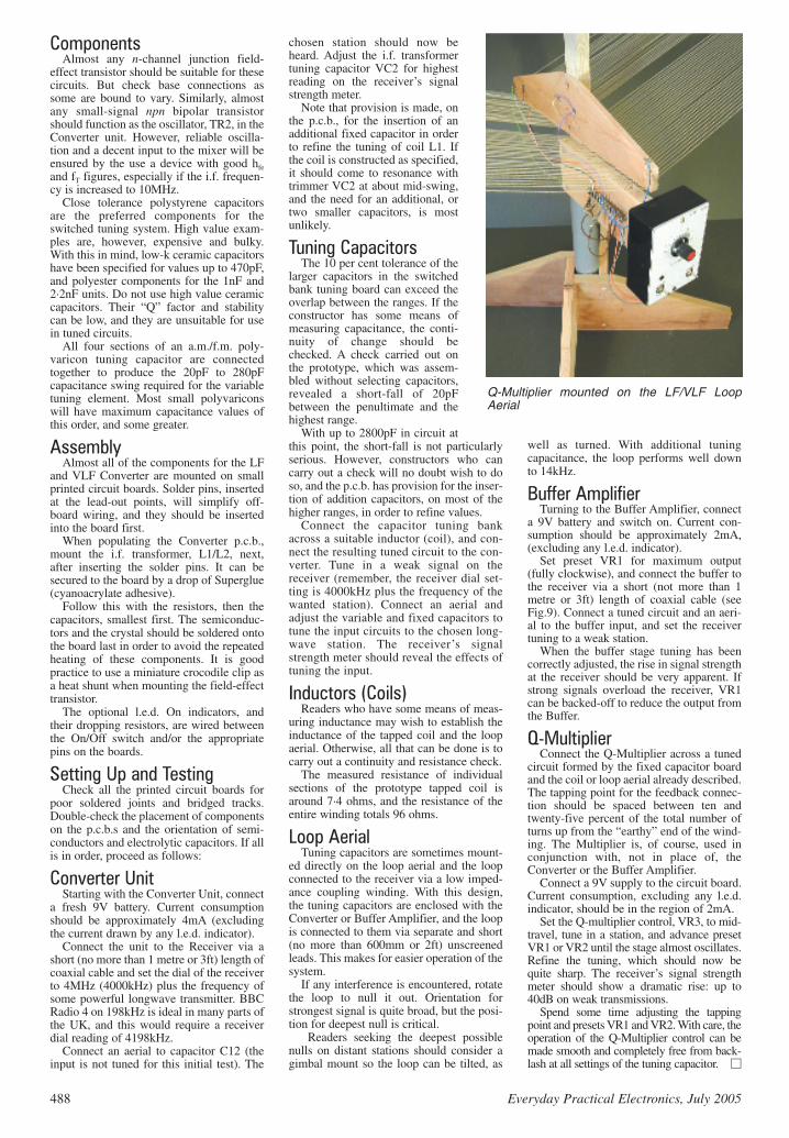
Loop AerialTuning capacitors are sometimes mount-
ed directly on the loop aerial and the loopconnected to the receiver via a low imped-ance coupling winding. With this design,the tuning capacitors are enclosed with theConverter or Buffer Amplifier, and the loopis connected to them via separate and short(no more than 600mm or 2ft) unscreenedleads. This makes for easier operation of thesystem.
If any interference is encountered, rotatethe loop to null it out. Orientation forstrongest signal is quite broad, but the posi-tion for deepest null is critical.
Readers seeking the deepest possiblenulls on distant stations should consider agimbal mount so the loop can be tilted, as
well as turned. With additional tuningcapacitance, the loop performs well downto 14kHz.
Buffer AmplifierTurning to the Buffer Amplifier, connect
a 9V battery and switch on. Current con-sumption should be approximately 2mA,(excluding any l.e.d. indicator).
Set preset VR1 for maximum output(fully clockwise), and connect the buffer tothe receiver via a short (not more than 1metre or 3ft) length of coaxial cable (seeFig.9). Connect a tuned circuit and an aeri-al to the buffer input, and set the receivertuning to a weak station.
When the buffer stage tuning has beencorrectly adjusted, the rise in signal strengthat the receiver should be very apparent. Ifstrong signals overload the receiver, VR1can be backed-off to reduce the output fromthe Buffer.
Q-MultiplierConnect the Q-Multiplier across a tuned
circuit formed by the fixed capacitor boardand the coil or loop aerial already described.The tapping point for the feedback connec-tion should be spaced between ten andtwenty-five percent of the total number ofturns up from the “earthy” end of the wind-ing. The Multiplier is, of course, used inconjunction with, not in place of, theConverter or the Buffer Amplifier.
Connect a 9V supply to the circuit board.Current consumption, excluding any l.e.d.indicator, should be in the region of 2mA.
Set the Q-multiplier control, VR3, to mid-travel, tune in a station, and advance presetVR1 or VR2 until the stage almost oscillates.Refine the tuning, which should now bequite sharp. The receiver’s signal strengthmeter should show a dramatic rise: up to40dB on weak transmissions.
Spend some time adjusting the tappingpoint and presets VR1 and VR2. With care, theoperation of the Q-Multiplier control can bemade smooth and completely free from back-lash at all settings of the tuning capacitor.