Page 1
LG data – Commercial in Confidence; Proprietary; US
Export Controlled
©2016 LG Fuel Cell Systems Inc.
The information in this document is the property of LG Fuel Cell Systems Inc. and may not be copied or communicated to a third
party, or used for any purpose other than that for which it is supplied without the express written consent of LG Fuel Cell Systems
Inc.
This information is given in good faith based upon the latest information available to LG Fuel Cell Systems Inc. No warranty or
representation is given concerning such information, which must not be taken as establishing any contractual or other commitment
binding upon LG Fuel Cell Systems Inc. or any of its subsidiary or associated companies.
LG Fuel Cell Systems Program and Technology Update
DOE 17th Annual SOFC Review, 19 July 2016
Shung Ik Lee and Adam Babcock
Page 2
LG data – Commercial in Confidence; Proprietary; US
Export Controlled
Contracts
Work performed by LG Fuel Cell
Systems under DOE contracts:
DE-FE0012077: SECA Coal-Based
Systems LGFCS
DE-FE0023337:Improved Reliability of
SOFC Systems
DE-FE0026098: Advanced Materials and
Manufacturing
2
Page 3
•LG data – Commercial in Confidence; Proprietary; US
Export Controlled
Outline
Performance Improvement
Cost Reduction
Durability
Block Testing
Advanced Materials and Manufacturing
Summary
3
Page 4
•LG data – Commercial in Confidence; Proprietary; US
Export Controlled
Outline
Performance Improvement
Fuel cell system operation strategy
ASR improvement for longer service life
and cost reduction
Cost reduction
Durability
Block Testing
Advanced Materials and Manufacturing
LGFCS Program
4
Page 5
•LG data – Commercial in Confidence; Proprietary; US
Export Controlled
Plant Operation Options Based on Stack Performance
Initial ASR and ASR degradation rate are key metrics for benchmarking cell technology
System design must be able to operate over a wide range of ASR (starting to end-of-life) while maintaining specified stack temperature range
Operation based on current technology developed to date
5
0%
20%
40%
60%
80%
100%
40%
50%
60%
70%
80%
90%
100%
0 1 2 3 4 5
Po
we
r O
utp
ut,
% R
ati
ng
DC
Eff
icie
nc
y
Time, Years
Plant Operation Options - Constant Power/Heat Release
ASR = 0.28 ohm-cm2
Power Rating →
← DC Efficiency
440 to 485 mA/cm2 current density
Page 6
•LG data – Commercial in Confidence; Proprietary; US
Export Controlled
EIS Tech. provide ASR benefit (0.04~0.05 Ω) compared with
IST Tech.
ASR Reduction Achievements
•* Manufacturing QA data
6
Page 7
•LG data – Commercial in Confidence; Proprietary; US
Export Controlled
Additional ASR Reduction Achieved using Nickelate Cathodes
Candidate nickelate cathodes have ~0.02 Ohm cm2 lower cell ASR
at 860C, 4bar
7
•4bar
Page 8
•LG data – Commercial in Confidence; Proprietary; US
Export Controlled
Current Status for Nickelates Difficult to achieve complete phase stability
But, still promising durability even with multiple
phases present
Recent further improvements in degree of phase
instability
8
•Nickelate composite II (PCT238 A2) Elapsed time : 7200hr
•Nickelate composite I (PCT222 B1) Elapsed time : 9500hr
~6 mohm-cm2/1000hr
•New Composite, 870C 500hrs
Page 9
•LG data – Commercial in Confidence; Proprietary; US
Export Controlled
Outline
Performance improvement
Cost reduction
Cell and stack design changes
Current density
System simplification for cost reduction
Durability
Block Testing
Advanced Materials and Manufacturing
LGFCS Program
9
Page 10
•LG data – Commercial in Confidence; Proprietary; US
Export Controlled
Cell & Tube Design Options for ASR Reduction & Power Increase
10
Smaller PIC dimension has
lower ASR contribution
Power increased using
longer tube (~100W/tube)
•P-Value=0.001
PIC ASR reduction: 0.012 Ohm cm2 (PCT)
Baseline
66Cells
82Cells longer tube
Page 11
•LG data – Commercial in Confidence; Proprietary; US
Export Controlled
In-Block Reforming Enables Higher Power Density
In Block Reforming reduces stack DT to allow higher power density for the
same air flow
Single tube mapping tests showed no evidence of performance loss with
various levels of IBR
Low ASR enables higher current density while maintaining efficiency
P = 19 kW
DT = 80 °C
IST configuration
P = 25 kW
DT = 80 °C
IBR configuration
Cell performance
•75% IBR
DNG + Recycle
DNG + Recycle
Partially Reformed
Increasing % IBR
No change in anode peak
11
Page 12
•LG data – Commercial in Confidence; Proprietary; US
Export Controlled
Anode Protection System Simplification for Cost Reduction
Operational scheme results in anode redox
A minimal number of redox cycles required for product
cost reduction by 75% from early design of Anode Protection Unit
•Early system designs utilized a
separate subsystem for system
scale APG generation
• Pellet Redox
• Exposure to air for 2 hrs at 900C
• 5 cycles
12
Page 13
•LG data – Commercial in Confidence; Proprietary; US
Export Controlled
Outline
Performance improvement
Cost reduction
Durability
Cathode
Anode
PIC
Degradation rate
Block Testing
Advanced Materials and Manufacturing
LGFCS Program
13
Page 14
•LG data – Commercial in Confidence; Proprietary; US
Export Controlled
MnOx Accumulation, Redistribution Status of Understanding, Solutions
Mn enrichment greater at low
temperature
14
Page 15
•LG data – Commercial in Confidence; Proprietary; US
Export Controlled
MnOx Accumulation, Redistribution Status of Understanding, Solutions
Mn enrichment greater at low
temperature
15
MnOx source appears to be from
throughout the cathode and CCC
layers. No significant localized
LSM stochiometry change
Even 5% A-site deficient CCC
has free-MnOx as-fabricated.
Page 16
•LG data – Commercial in Confidence; Proprietary; US
Export Controlled
MnOx Accumulation, Redistribution Status of Understanding, Solutions
Mn enrichment greater at low
temperature
16
MnOx source appears to be from
throughout the cathode and CCC
layers. No significant localized
LSM stochiometry change
Even 5% A-site deficient CCC
has free-MnOx as-fabricated.
Localized at interface (driving
force?)
Overpotential and/or pO2
Page 17
•LG data – Commercial in Confidence; Proprietary; US
Export Controlled
MnOx Accumulation, Redistribution Status of Understanding, Solutions
Mn enrichment greater at low
temperature
17
MnOx source appears to be from
throughout the cathode and CCC
layers. No significant localized
LSM stochiometry change
Even 5% A-site deficient CCC
has free-MnOx as-fabricated.
Localized at interface (driving
force?)
Overpotential and/or pO2
Mn valence along interface
Using EELS
As fired
900C
800
Page 18
•LG data – Commercial in Confidence; Proprietary; US
Export Controlled
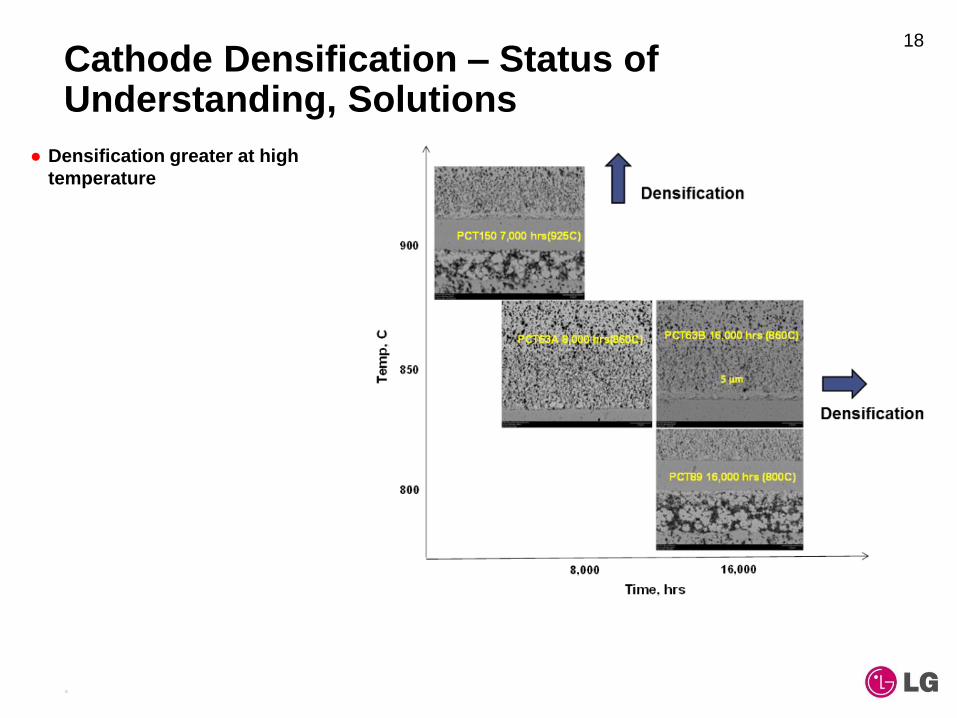
Cathode Densification – Status of Understanding, Solutions
Densification greater at high
temperature
18
Page 19
•LG data – Commercial in Confidence; Proprietary; US
Export Controlled
Cathode Densification – Status of Understanding, Solutions
Densification greater at high
temperature
Densification is greatest under
localized low pO2 if kinetics are
high
Pressurized SOFC benefit higher
pO2
19
Degree of A-site deficiency
influences densification
Page 20
•LG data – Commercial in Confidence; Proprietary; US
Export Controlled
Cathode Densification – Status of Understanding, Solutions
Densification greater at high
temperature
Densification is greatest under
localized low pO2 if kinetics are
high
Pressurized SOFC benefit higher
pO2
20
Degree of A-site deficiency
influences densification
B-site dopant selection can
reduce densification
(B site doping)
Acceleration test 1000hr
Page 21
•LG data – Commercial in Confidence; Proprietary; US
Export Controlled
8um CA
7um DL 8um CA 15um CA
Cathode Densification – Status of Understanding, Solutions
Densification greater at high
temperature
Densification is greatest under
localized low pO2 if kinetics are
high
Pressurized SOFC benefit higher
pO2
21
Degree of A-site deficiency
influences densification
B-site dopant selection can
reduce densification
Densification increases Rp
Page 22
•LG data – Commercial in Confidence; Proprietary; US
Export Controlled
Anode Degradation– Status of Understanding, Solutions
Bilayer anode+ACC versus single
layer
Avoidance of interfaces
resistance
22
925C, 4000hr
925oC 5000hr
Page 23
•LG data – Commercial in Confidence; Proprietary; US
Export Controlled
925C, high steam ,4000Hr
Anode Degradation– Status of Understanding, Solutions
Bilayer anode+ACC versus single
layer
Avoidance of interfaces
resistance
23
Ni accumulation along interface
at high temp and higher Uf
Page 24
•LG data – Commercial in Confidence; Proprietary; US
Export Controlled
Anode Degradation– Status of Understanding, Solutions
Bilayer anode+ACC versus single
layer
Avoidance of interfaces
resistance
24
Ni accumulation along interface
at high temp and higher Uf
Loss of TPB
Redox event
Page 25
•LG data – Commercial in Confidence; Proprietary; US
Export Controlled
Anode Degradation– Status of Understanding, Solutions
Bilayer anode+ACC versus single
layer
Avoidance of interfaces
resistance
25
Ni accumulation along interface
at high temp and higher Uf
Loss of TPB
Anode-side conductivity
retention important for durability
Page 26
•LG data – Commercial in Confidence; Proprietary; US
Export Controlled
Anode Degradation– Status of Understanding, Solutions
Bilayer anode+ACC versus single
layer
Avoidance of interfaces
resistance
26
Ni accumulation along interface
at high temp and higher Uf
Loss of TPB
Anode-side conductivity
retention important for durability
Mn penetration through
Electrolyte was not observed
thus far (16000hrs)
925C, 4000hr
925oC 5000hr
925C, high steam ,4000Hr
Page 27
•LG data – Commercial in Confidence; Proprietary; US
Export Controlled
Primary Interconnect Degradation– Status of Understanding, Solutions
Anode-side barrier layers
were applied to primary
interconnect region to
improve durability
Cathode side barrier layers
further improving interface
quality
Lower initial ASR
Improved long term
durability
27
Page 28
•LG data – Commercial in Confidence; Proprietary; US
Export Controlled
Durability Trends: 3-10 mohm-cm2/1000 hrs
New cathode bundle test (ATBT6) at 1 bar demonstrated < 7
mohm-cm2/1k hrs over 2 year test
Subscale cells (PCT189) demonstrated < 3mohm-cm2/1k hrs
over 2 year test
Correspond to 0.10~0.15%/1000hr power degradation rate
28
Page 29
•LG data – Commercial in Confidence; Proprietary; US
Export Controlled
Plant Life Improved with Lower ASR and Degradation Rate
Reduction of degradation rate from 8 to 5 mohm-cm2/1k hrs with ASR of
0.24 ohm-cm2 permits nearly constant power operation over 5 year life
ASR reduction using lower cathode Rp + Shorter PIC + thin wall substrates
> 0.04 Ohm cm2
Average efficiency also significantly higher
29
0%
20%
40%
60%
80%
100%
40%
50%
60%
70%
80%
90%
100%
0 1 2 3 4 5
Po
we
r O
utp
ut,
% R
ati
ng
DC
Eff
icie
nc
y
Time, Years
Plant Operation Options - Constant Power/Heat Release
ASR = 0.28 ohm-cm2
ASR = 0.24 ohm-cm2, Lower Degradation
Power Rating →
← DC Efficiency
440 to 485 mA/cm2 current density
Page 30
•LG data – Commercial in Confidence; Proprietary; US
Export Controlled
Outline
Performance improvement
Cost reduction
Durability
Block Testing
Block Test T1418 & T1315
IBR Block Test T1506
Advanced Materials and Manufacturing
LGFCS Program
30
Page 31
LG data – Commercial in Confidence; Proprietary; US
Export Controlled
Block Testing Matching Product Cycle, Components and Operating Conditions
Turbo-Generator
Fuel Cell
Cathode
Fuel
Cell
Anode
OGB
Anode Ejector
Cathode Ejector
Turbo-Generator
RRFCS NG “Dry Cycle” Configuration
Auxiliary
Ejector
R
E
F
O
R
M
E
R
R
E
F
O
R
M
E
R
Auxiliary
Heat Exchanger
Heat Source for Cathode Loop;
Partially-Spent Anode Gas,
Heated Cathode Loop Air,
and Hot Recycle
De-Sulfurized
NG
Recuperator
Initial design of block testing rigs
Representative of cycle and components
Not packaged for product (T13xx, T14xx) Integrated block
Design for product
(T1506)
Page 32
LG data – Commercial in Confidence; Proprietary; US
Export Controlled
T1418: First Block Test of EIS Technology
Test Identification Strip 1 – EIS1 cathode &
lower ASR interconnect
Strips 2-4 IST (Epsilon)
standard strips
Test Objectives Test 5000 hours with
power degradation
< 0.75%/1000 hrs
Results 1.30% Power Degradation/1khrs
0.30 ohm-cm2 ASR at 1500 hours
was as expected
Average DC Efficiency ~ 62%
Completed 1450 hours on load
Test run short due to BOP issues
Decision to convert rig to IB standard
0%
10%
20%
30%
40%
50%
60%
70%
80%
90%
100%
0.0
2.0
4.0
6.0
8.0
10.0
12.0
14.0
16.0
18.0
0 200 400 600 800 1000 1200 1400 1600
An
od
e L
oo
p E
ffic
ien
cy
Blo
ck P
ow
er,
kW
Time on Load, hours
T1418 (SOFC76) - Power and DC Efficiency
Total Power
Efficiency
30-Mar-16 10:26:51
32
Page 33
LG data – Commercial in Confidence; Proprietary; US
Export Controlled
T1315: EIS Cathode Screening Block Test
Test Objective Test 2000 hours with power
degradation < 1.5%/1000 hrs
Results 0.78% Power Degradation/1khrs
Average DC Efficiency ~ 60%
Completed 2049 hours on load
Test Identification 4 different cathode configurations
Standard IST (epsilon)
3 EIS candidates
Lower ASR interconnect
IST (Epsilon) standard anode
EIS
1E
IS2
EIS
1E
IS2
EIS
1e
EIS
3E
IS2
31
67
31
68
31
67
31
68
31
72
3169
21
70
31
68
0%
10%
20%
30%
40%
50%
60%
70%
80%
90%
100%
0.0
2.0
4.0
6.0
8.0
10.0
12.0
14.0
16.0
18.0
0 200 400 600 800 1000 1200 1400 1600 1800 2000 2200 2400
An
od
e E
lectr
ical E
ffic
ien
cy
Blo
ck P
ow
er,
kW
Time at Temperature, hours
T1315 (Block 3 in SOFC73) - Block Power
Total Power
DC Electrical Efficiency
18-Apr-16 13:20:00
33
Page 34
•LG data – Commercial in Confidence; Proprietary; US
Export Controlled
T1506: Demonstration of In-Block Reforming
• Initial power 25.6 kW
• Highest single block power
• Test duration 511 hours on load
• Lowest block ASR tested
• Achieved <80°C dT
• Strip Technology
• EIS1 Cathode
• Lower ASR interconnect
800
820
840
860
880
900
920
0.10
0.15
0.20
0.25
0.30
0.35
0.40
0 100 200 300 400 500 600
Str
ip A
vera
ge T
em
pera
ture
s (
ºC),
LH
V (
kJ/m
ol)
Blo
ck
Ave
rag
e A
SR
, o
hm
-cm
2
Time on Test, hours
T1506 - IBR Block Test - Average Block ASR and Temperature
From Overall Current/Voltage
Cathode Average Temperature
Total Power = 25.14 KW
01-Jul-16 04:10:31
0%
10%
20%
30%
40%
50%
60%
70%
80%
0.0
5.0
10.0
15.0
20.0
25.0
30.0
0 100 200 300 400 500 600
DC
Ele
ctr
ical E
ffic
ien
cy
Blo
ck P
ow
er,
kW
Time on Test, hours
T1506 - IBR Block Test - Block Power and Anode Loop Efficiency
01-Jul-16 04:10:31
Total Power = 25.14 KW
Time on load = 510.8 hrs
True value of ASR 0.27-0.28, ~0.023 higher
than calculated value - owing to calculation
assumption of linear variation of Nernst voltage
from inlet to outlet
34
Page 35
LG data – Commercial in Confidence; Proprietary; US
Export Controlled
0.00
0.05
0.10
0.15
0.20
0.25
0.30
0.35
0.40
0.45
0.50
0 500 1000 1500 2000 2500
AS
R o
hm
-cm
2
Time, hours
Comparative ASRs
T1314
T1315
T1418
PBT20
T1506
IBR Block Performance: Within Range of Sub-scale Tests
• Improved block ASR from
T1314 to T1315/T1418
• Excellent correlation from
bundle PBT20 to block
T1506
• ASR degradation rates
tend to converge after
longer test periods
0
20
40
60
80
100
120
140
0 500 1000 1500 2000 2500
AS
R D
eg
rad
ati
on
, m
oh
m-c
m2/1
00
0 h
rs
Time, hours
Comparative ASR Degradation Rates
T1314
T1315
T1418
PBT20
T1506
35
Page 36
LG data – Commercial in Confidence; Proprietary; US
Export Controlled
Block Performance Summary 36
Parameter T1314 T1418 T1315 T1506
Initial Power (Normalized for 5 strips)
18.8 kW 19.5 kW 19.7 kW 25.6 kW
Starting ASR (ohm-cm2)
0.35 0.28 0.28 0.27Note 1
Current Density (mA/cm2) 380 380 380 530
Fuel (@ 75 – 80% Uf) Bottled CH4 PNG Bottled CH4 PNG
Power Degradation (per 1000hrs) 1.2% 1.3% 0.78% Note 2
Duration (hours) 3040 1450 2049 520Note 3
Cell Technology Pre-Eps Eps, EIS EIS EIS + IBR
Note 1: Accounting for non-linear Nernst voltage
Note 2: Power Degradation rate given once test accumulates >1000hrs of test time
Note 3: Still under test
Page 37
LG data – Commercial in Confidence; Proprietary; US
Export Controlled
Outline
Performance improvement
Cost reduction
Durability
Block Testing
Advanced Materials and Manufacturing
Task 2.0
Task 3.0
LGFCS Program
37
Page 38
LG data – Commercial in Confidence; Proprietary; US
Export Controlled
Advanced Materials and Manufacturing
Task 2.0: Identify Candidate Components Cathode and Anode Ejectors
Cathode and Anode Pipework
Task 3.1: Identify Materials Anode Ejector (low temp.) - continue using SS
310/316
Auxiliary Ejector (high temperature) materials considered H120, RA330, AFA25, 601, and 230
Task 3.2 Identify Processes
38
• additive manufacturing (AM) • spin forming
• metal injection molding (MIM) • lost wax casting
• hot isostatic pressing (HIP) • other processes
Page 39
LG data – Commercial in Confidence; Proprietary; US
Export Controlled
Advanced Materials Project Status Summary
Key Findings Five candidate alloys identified based on material
requirements
Preliminary cost study suggests ~50% reduction for aux. ejector
Metal Injection Molded (MIM) coupling fitting cost ~$8 & $9 at 50 MW quantities
Estimated 77% - 89% cost reduction vs low-volume machined component
Lessons Learned Additive Manufacturing Process is only cost effective for
the complex nozzle assembly
Other manufacturing processes are being explored spin forming
lost wax casting
39
Page 40
LG data – Commercial in Confidence; Proprietary; US
Export Controlled
Summary
Significant progress made regarding performance improvements and durability. There is a better understanding on how to increase the life of the LGFCS fuel cell. These improvements will have a direct impact on reducing costs.
Block testing, though challenging, has shown that ASR tracks across multiple scales. Improvements in cell technology and system performance allowed for LGFCS’s best block test to date.
The advanced materials and manufacturing project continues to support material selection and cost reduction of critical components.
40
Page 41
LG data – Commercial in Confidence; Proprietary; US
Export Controlled
Acknowledgements
Special thanks to LGFCS project managers Patcharin Burke, Shailesh Vora, and the entire SOFC program management team
This material is based upon work supported by the U.S. Department of Energy, National Energy Technology Laboratory under Award Number DE-FE0012077, DE-FE0023337, and DE-FE0026098
Disclaimer: This report was prepared as an account of work sponsored by an agency of the United States Government. Neither the United States government nor any agency thereof, nor any of their employees, makes any warranty, express or implied, or assumes any legal liability or responsibility for the accuracy, completeness or usefulness of any information, apparatus, product, or process disclosed, or represents that its use would not infringe privately owned rights. Reference herein to any specific commercial product, process, or service by trade name, trademark, manufacturer, or otherwise does not necessarily constitute or imply its endorsement, recommendation, or favoring by the United States Government or any agency thereof. The views and opinions of the authors expressed herein do not necessarily state or reflect those of the United States Government of any agency thereof.
41