Page 1
LED Driver
www.lginnotek.com Revised 23 May 2016 (REV. 0.2) 1 / 34
Retrofit Type
Existed LED Driver or Ballast
New Fixture Type
Programmable LED Driver
Zigbee
LG Innotek can providing to customer
Wireless solution for LED and Conventional Lighting depend on Lighting Fixture
Application Note
Page 2
LED Driver
www.lginnotek.com Revised 23 May 2016 (REV. 0.2) 2 / 34
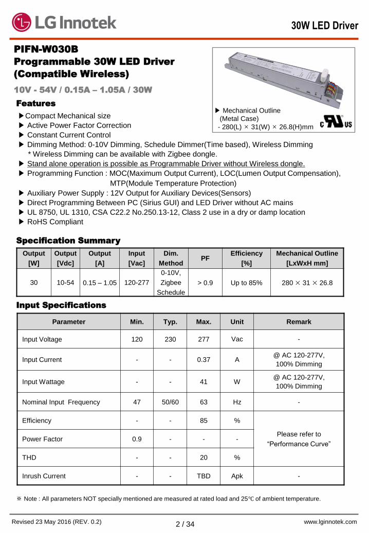
PIFN-W030B
Programmable 30W LED Driver
(Compatible Wireless)
Features
Compact Mechanical size
Active Power Factor Correction
Constant Current Control
Dimming Method: 0-10V Dimming, Schedule Dimmer(Time based), Wireless Dimming
* Wireless Dimming can be available with Zigbee dongle.
Stand alone operation is possible as Programmable Driver without Wireless dongle.
Programming Function : MOC(Maximum Output Current), LOC(Lumen Output Compensation),
MTP(Module Temperature Protection)
Auxiliary Power Supply : 12V Output for Auxiliary Devices(Sensors)
Direct Programming Between PC (Sirius GUI) and LED Driver without AC mains
UL 8750, UL 1310, CSA C22.2 No.250.13-12, Class 2 use in a dry or damp location
RoHS Compliant
Output
[W]
Output
[Vdc]
Output
[A]
Input
[Vac]
Dim.
Method PF
Efficiency
[%]
Mechanical Outline
[LxWxH mm]
30 10-54 0.15 – 1.05 120-277
0-10V,
Zigbee
Schedule
> 0.9 Up to 85% 280 × 31 × 26.8
Input Specifications
Parameter Min. Typ. Max. Unit Remark
Input Voltage 120 230 277 Vac -
Input Current - - 0.37 A @ AC 120-277V,
100% Dimming
Input Wattage - - 41 W @ AC 120-277V,
100% Dimming
Nominal Input Frequency 47 50/60 63 Hz -
Efficiency - - 85 %
Please refer to
“Performance Curve” Power Factor 0.9 - - -
THD - - 20 %
Inrush Current - - TBD Apk -
※ Note : All parameters NOT specially mentioned are measured at rated load and 25 of ambient temperature.
10V - 54V / 0.15A – 1.05A / 30W
Specification Summary
Mechanical Outline
(Metal Case)
- 280(L) × 31(W) × 26.8(H)mm
30W LED Driver
Page 3
LED Driver
www.lginnotek.com Revised 23 May 2016 (REV. 0.2) 3 / 34
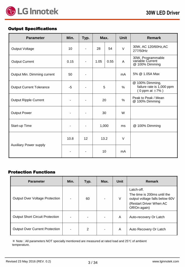
Output Specifications
Protection Functions
Parameter Min. Typ. Max. Unit Remark
Output Over Voltage Protection - 60 - V
Latch-off.
The time is 200ms until the
output voltage falls below 60V
(Restart Driver When AC
Off/On again)
Output Short Circuit Protection - - - A Auto-recovery Or Latch
Output Over Current Protection - 2 - A Auto Recovery Or Latch
※ Note : All parameters NOT specially mentioned are measured at rated load and 25 of ambient
temperature.
Parameter Min. Typ. Max. Unit Remark
Output Voltage 10 - 28 54 V 30W, AC 120/60Hz,AC
277/50Hz
Output Current 0.15 - 1.05 0.55 A 30W, Programmable variable Current @ 100% Dimming
Output Min. Dimming current 50 - mA 5% @ 1.05A Max
Output Current Tolerance -5 - 5 %
@ 100% Dimming, failure rate is 1,000 ppm ( 0 ppm at ±7% )
Output Ripple Current - - 20 % Peak to Peak / Mean @ 100% Dimming
Output Power - - 30 W
Start-up Time - - 1,000 ms @ 100% Dimming
Auxiliary Power supply
10.8 12 13.2 V
- - 10 mA
30W LED Driver
Page 4
LED Driver
www.lginnotek.com Revised 23 May 2016 (REV. 0.2) 4 / 34
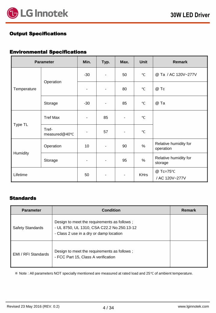
Output Specifications
Environmental Specifications
Parameter Min. Typ. Max. Unit Remark
Temperature
Operation
-30 - 50 @ Ta / AC 120V~277V
- - 80 @ Tc
Storage -30 - 85 @ Ta
Type TL
Tref Max - 85 -
Tref-
measured@40 - 57 -
Humidity
Operation 10 - 90 % Relative humidity for
operation
Storage - - 95 % Relative humidity for
storage
Lifetime 50 - - KHrs @ Tc=75
/ AC 120V~277V
※ Note : All parameters NOT specially mentioned are measured at rated load and 25 of ambient temperature.
Parameter Condition Remark
Safety Standards
Design to meet the requirements as follows ;
- UL 8750, UL 1310, CSA C22.2 No.250.13-12
- Class 2 use in a dry or damp location
EMI / RFI Standards Design to meet the requirements as follows ;
- FCC Part 15, Class A verification
Standards
30W LED Driver
Page 5
LED Driver
www.lginnotek.com Revised 23 May 2016 (REV. 0.2) 5 / 34
Output Voltage [V]
Ou
tput
Curr
ent[
A]
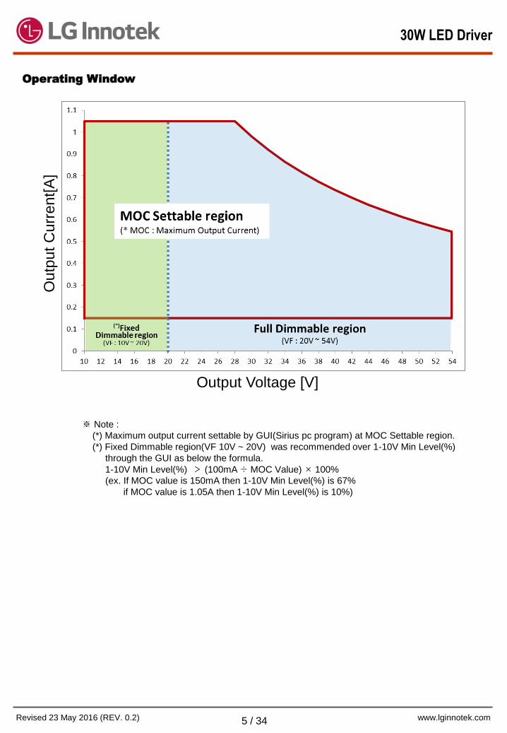
Operating Window
※ Note :
(*) Maximum output current settable by GUI(Sirius pc program) at MOC Settable region.
(*) Fixed Dimmable region(VF 10V ~ 20V) was recommended over 1-10V Min Level(%)
through the GUI as below the formula.
1-10V Min Level(%) > (100mA ÷ MOC Value) × 100%
(ex. If MOC value is 150mA then 1-10V Min Level(%) is 67%
if MOC value is 1.05A then 1-10V Min Level(%) is 10%)
30W LED Driver
Page 6
LED Driver
www.lginnotek.com Revised 23 May 2016 (REV. 0.2) 6 / 34
Performance curve
30W LED Driver
Page 7
LED Driver
www.lginnotek.com Revised 23 May 2016 (REV. 0.2) 7 / 34
Programmable Features
Parameter Min. Typ. Max. Unit Remark
LED Module Working Hours 0 - 127.5 KHr Min. Step : 1Hr
Time Tolerance -4 4 % Time Accuracy
2. LED Module Working Hours(MWH)
Parameter Min. Typ. Max. Unit Remark
Output Current 150 - 1050 mA Min. Step : 1mA
3. Maximum Output Current(MOC)
Parameter Min. Typ. Max. Unit Remark
1-10V Min Level 5 - 100 % Min. Step : 1%
4. 1-10V Dimming
Parameter Min. Typ. Max. Unit Remark
1-10V Dimming 5 - 100 %
Schedule Dimmer 5 - 100 % Min. step : 1%
Zigbee Dimming 5 - 100 % Min. step : 1%
1. Dimming Interface
※ Zigbee mode is supported only if LED driver is combined with Zigbee module)
30W LED Driver
Page 8
LED Driver
www.lginnotek.com Revised 23 May 2016 (REV. 0.2) 8 / 34
Programmable Features
Parameter Min. Typ. Max. Unit Remark
Dimming Schedule 1 - 5 Step Min. step : 1min
Dim Level 5 - 100 % Min. Step : 1%
(Possible to LED OFF at 0%)
Override Hold Time 0 - 60 min Min. Step : 1min
7. Schedule Dimmer(Time Based)
Parameter Min. Typ. Max. Unit Remark
Tstart 50 - 85 Min. Step : 1, Temperature
@ Dim Start
Tstop 55 - 95 Min. Step : 1, Temperature
@ Dim Stop
Tmax 60 - 105 Min. Step : 1, Temperature
@ Dim Off
Temperature Tolerance -3 - 3 Tolerance @ Tstart, Tstop,
Tmax
Dim Level 10 - 90 % Min. Step : 1%, Dim Level @
Tstop
6. Module Temperature Protection(MTP)
※ Note : External MTP is settable based on NCPXH103(ex. NCP18XH103)
or equivalent thermistor(10kΩ at 25).
※ To apply dimming mode as schedule dimmer completely, it is recommended to apply AC power once again.
Parameter Min. Typ. Max. Unit Remark
Working Hours (Max. 16 steps) 0 - 127.5 KHr Min. step : 500hrs
Dim. Level (Max. 16 steps) 10 - 130 % Min. step: 1%
Operating Time Accuracy -4 - 4 % Time Accuracy
5. Lumen Output Compensation
30W LED Driver
Page 9
LED Driver
www.lginnotek.com Revised 23 May 2016 (REV. 0.2) 9 / 34
Dimming Control
Dim+/- Current
Open or More than 8.5V Driver-max Current (100%)
1V – 0.5V(Dim To Off Level) Driver-min Current
0.5V(Dim To Off Level)~0V or Short Driver-Off Current (0%)
30W LED Driver
Page 10
LED Driver
www.lginnotek.com Revised 23 May 2016 (REV. 0.2) 10 / 34
PIFN-W055B
Programmable 55W LED Driver
(Compatible Wireless)
Features
Compact Mechanical size
Active Power Factor Correction
Constant Current Control
Dimming Method: 0-10V Dimming, Schedule Dimmer(Time based)
* Wireless Dimming can be available with Zigbee dongle.
Stand alone operation is possible as Programmable Driver without Wireless dongle.
Programming Function : MOC(Maximum Output Current), LOC(Lumen Output Compensation),
MTP(Module Temperature Protection)
Auxiliary Power Supply : 12V Output for Auxiliary Devices(Sensors)
Direct Programming Between PC (Sirius GUI) and LED Driver without AC mains
UL 8750, UL 1310, CSA C22.2 No.250.13-12, Class 2 use in a dry or damp location
RoHS Compliant
Output
[W]
Output
[Vdc]
Output
[A]
Input
[Vac]
Dim.
Method PF
Efficiency
[%]
Mechanical Outline
[LxWxH mm]
55 10-54 0.4 – 1.5 120-277
0-10V,
Zigbee
Schedule
> 0.9 Up to 87% 280 × 31 × 26.8
Input Specifications
Parameter Min. Typ. Max. Unit Remark
Input Voltage 120 230 277 Vac -
Input Current - - 0.6 A @ AC 120-277V,
100% Dimming
Input Wattage - - 67 W @ AC 120-277V,
100% Dimming
Nominal Input Frequency 47 50/60 63 Hz -
Efficiency - - 87 %
Please refer to
“Performance Curve” Power Factor 0.9 - - -
THD - - 20 %
Inrush Current 16 - 60 Apk @Measurement Value
※ Note : All parameters NOT specially mentioned are measured at rated load and 25 of ambient temperature.
10V - 54V / 0.4A – 1.5A / 55W
Specification Summary
Mechanical Outline
(Metal Case)
- 280(L) × 31(W) × 26.8(H)mm
55W LED Driver
Page 11
LED Driver
www.lginnotek.com Revised 23 May 2016 (REV. 0.2) 11 / 34
Output Specifications
Protection Functions
Parameter Min. Typ. Max. Unit Remark
Output Over Voltage Protection - 59 - V
Latch-off.
The time is 200ms until the
output voltage falls below 60V
(Restart Driver When AC
Off/On again)
Output Short Circuit Protection - - - A Auto-recovery Or Latch
Output Over Current Protection - 2 - A Auto Recovery Or Latch
※ Note : All parameters NOT specially mentioned are measured at rated load and 25 of ambient temperature.
Parameter Min. Typ. Max. Unit Remark
Output Voltage 10 - 36 54 V 55W, AC 120/60Hz,AC
277/50Hz
Output Current 0.4 - 1.5 1.02 A 55W, Programmable variable Current @ 100% Dimming
Output Min. Dimming current 75 - mA 5% @1.5A Max
Output Current Tolerance -5 - 5 %
@ 100% Dimming, failure rate is 1,000 ppm ( 0 ppm at ±7% )
Output Ripple Current -30 - 30 % Peak to Peak / Mean @ 100% Dimming
Output Power - - 55 W
Start-up Time - - 1,000 ms @ 100% Dimming
Auxiliary Power supply
10.8 12 13.2 V
- - 10 mA
55W LED Driver
Page 12
LED Driver
www.lginnotek.com Revised 23 May 2016 (REV. 0.2) 12 / 34
Output Specifications
Environmental Specifications
※ Note : All parameters NOT specially mentioned are measured at rated load and 25 of ambient temperature.
Parameter Condition Remark
Safety Standards
Design to meet the requirements as follows ;
- UL 8750, UL 1310, CSA C22.2 No.250.13-12
- Class 2 use in a dry or damp location
EMI / RFI Standards Design to meet the requirements as follows ;
- FCC Part 15, Class A verification
Standards
Parameter Min. Typ. Max. Unit Remark
Temperature
Operation
-30 - 50 @ Ta / AC 120V~277V
- - 80 @ Tc
Storage -30 - 85 @ Ta
Type TL
Tref Max 82
@Safety
Tref-
measured@40 70
Humidity
Operation 10 - 90 % Relative humidity for
operation
Storage - - 95 % Relative humidity for
storage
Lifetime 50 - - KHrs @ Tc=75
/ AC 120V~277V
55W LED Driver
Page 13
LED Driver
www.lginnotek.com Revised 23 May 2016 (REV. 0.2) 13 / 34
Output Voltage [V]
※ Note :
(*) Maximum output current settable by GUI(Sirius pc program) at MOC Settable region.
(*) Fixed Dimmable region(VF 10V ~ 20V) was recommended over 1-10V Min Level(%)
through the GUI as below the formula.
1-10V Min Level(%) > (150mA ÷ MOC Value) × 100%
(ex. If MOC value is 400mA then 1-10V Min Level(%) is 38%
if MOC value is 1.5A then 1-10V Min Level(%) is 10%)
Outp
ut
Cu
rrent[
A]
Operating Window
55W LED Driver
Page 14
LED Driver
www.lginnotek.com Revised 23 May 2016 (REV. 0.2) 14 / 34
Performance curve
55W LED Driver
Page 15
LED Driver
www.lginnotek.com Revised 23 May 2016 (REV. 0.2) 15 / 34
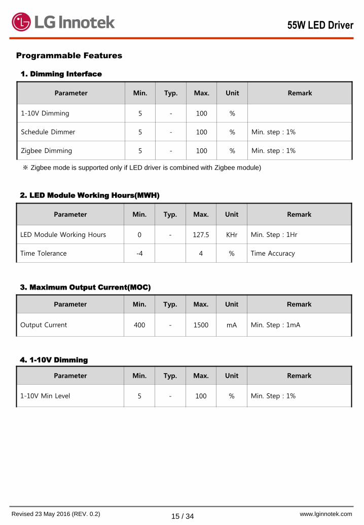
Programmable Features
Parameter Min. Typ. Max. Unit Remark
LED Module Working Hours 0 - 127.5 KHr Min. Step : 1Hr
Time Tolerance -4 4 % Time Accuracy
2. LED Module Working Hours(MWH)
Parameter Min. Typ. Max. Unit Remark
Output Current 400 - 1500 mA Min. Step : 1mA
3. Maximum Output Current(MOC)
Parameter Min. Typ. Max. Unit Remark
1-10V Min Level 5 - 100 % Min. Step : 1%
4. 1-10V Dimming
Parameter Min. Typ. Max. Unit Remark
1-10V Dimming 5 - 100 %
Schedule Dimmer 5 - 100 % Min. step : 1%
Zigbee Dimming 5 - 100 % Min. step : 1%
1. Dimming Interface
※ Zigbee mode is supported only if LED driver is combined with Zigbee module)
55W LED Driver
Page 16
LED Driver
www.lginnotek.com Revised 23 May 2016 (REV. 0.2) 16 / 34
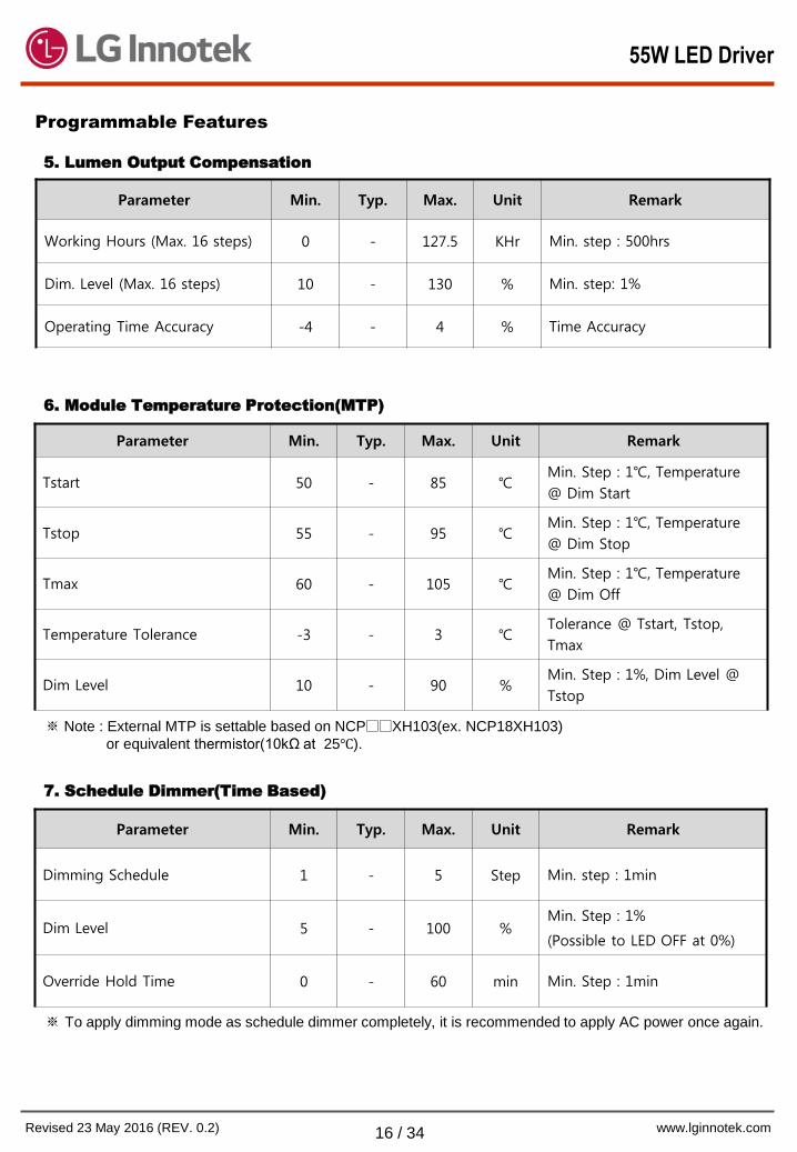
Programmable Features
Parameter Min. Typ. Max. Unit Remark
Dimming Schedule 1 - 5 Step Min. step : 1min
Dim Level 5 - 100 % Min. Step : 1%
(Possible to LED OFF at 0%)
Override Hold Time 0 - 60 min Min. Step : 1min
7. Schedule Dimmer(Time Based)
Parameter Min. Typ. Max. Unit Remark
Tstart 50 - 85 Min. Step : 1, Temperature
@ Dim Start
Tstop 55 - 95 Min. Step : 1, Temperature
@ Dim Stop
Tmax 60 - 105 Min. Step : 1, Temperature
@ Dim Off
Temperature Tolerance -3 - 3 Tolerance @ Tstart, Tstop,
Tmax
Dim Level 10 - 90 % Min. Step : 1%, Dim Level @
Tstop
6. Module Temperature Protection(MTP)
※ Note : External MTP is settable based on NCPXH103(ex. NCP18XH103)
or equivalent thermistor(10kΩ at 25).
Parameter Min. Typ. Max. Unit Remark
Working Hours (Max. 16 steps) 0 - 127.5 KHr Min. step : 500hrs
Dim. Level (Max. 16 steps) 10 - 130 % Min. step: 1%
Operating Time Accuracy -4 - 4 % Time Accuracy
5. Lumen Output Compensation
※ To apply dimming mode as schedule dimmer completely, it is recommended to apply AC power once again.
55W LED Driver
Page 17
LED Driver
www.lginnotek.com Revised 23 May 2016 (REV. 0.2) 17 / 34
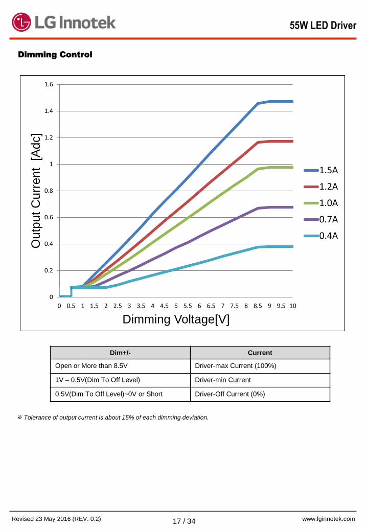
Dimming Control
※ Tolerance of output current is about 15% of each dimming deviation.
Dim+/- Current
Open or More than 8.5V Driver-max Current (100%)
1V – 0.5V(Dim To Off Level) Driver-min Current
0.5V(Dim To Off Level)~0V or Short Driver-Off Current (0%)
0
0.2
0.4
0.6
0.8
1
1.2
1.4
1.6
0 0.5 1 1.5 2 2.5 3 3.5 4 4.5 5 5.5 6 6.5 7 7.5 8 8.5 9 9.5 10
Outp
ut
Curr
ent
[A
dc]
Dimming Voltage[V]
1.5A
1.2A
1.0A
0.7A
0.4A
55W LED Driver
Page 18
LED Driver
www.lginnotek.com Revised 23 May 2016 (REV. 0.2) 18 / 34
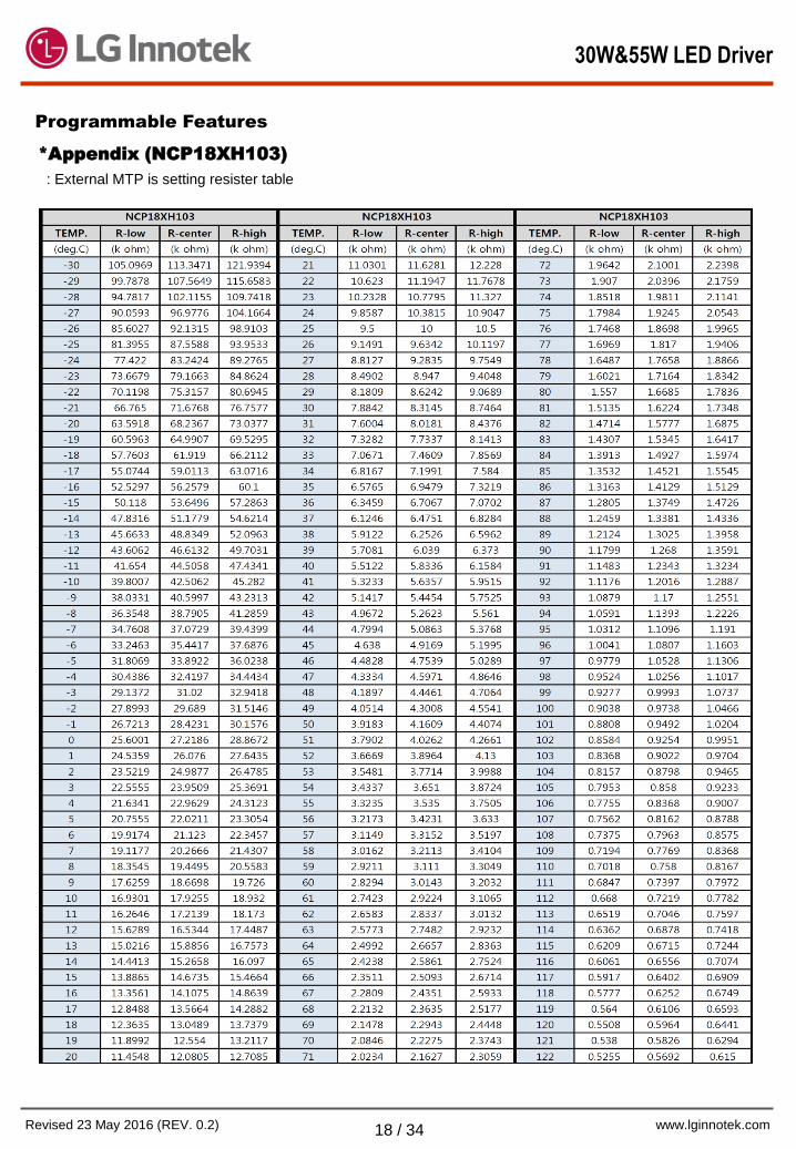
*Appendix (NCP18XH103)
: External MTP is setting resister table
Programmable Features
30W&55W LED Driver
Page 19
LED Driver
www.lginnotek.com Revised 23 May 2016 (REV. 0.2) 19 / 34
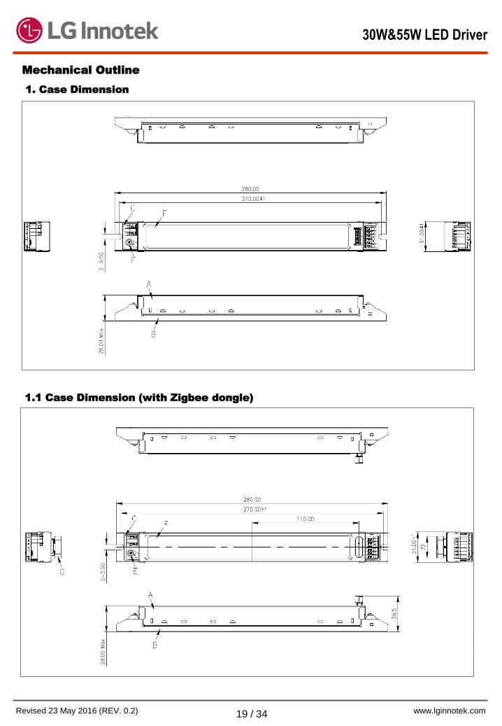
Mechanical Outline
1. Case Dimension
1.1 Case Dimension (with Zigbee dongle)
30W&55W LED Driver
Page 20
LED Driver
www.lginnotek.com Revised 23 May 2016 (REV. 0.2) 20 / 34
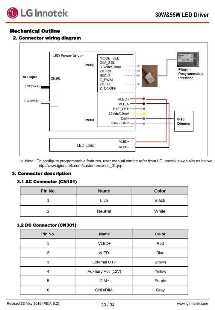
LIVE(Black)
LIVE(White)
AC Input
LED Power Driver
VLED+
VLED-
EXT_OTP
12Vdc/10mA
Dim+
Dim- / GND 0-10
Dimmer
VLED+
VLED- LED Load
2. Connector wiring diagram
CN101
CN301
3. Connector description
3.1 AC Connector (CN101)
Pin No. Name Color
1 Live Black
2 Neutral White
Mechanical Outline
Plug-in
Programmable
Interface
MODE_SEL
DIM_SEL
3.3Vdc/10mA
ZB_RX
SGND
Z_PWM
ZB_TX
Z_ONOFF
CN302
3.2 DC Connector (CN301)
Pin No. Name Color
1 VLED+ Red
2 VLED- Blue
3 External OTP Brown
4 Auxiliary Vcc (12V) Yellow
5 DIM+ Purple
6 GND/DIM- Gray
※ Note : To configure programmable features, user manual can be refer from LG Innotek’s web site as below
http://www.lginnotek.com/customer/sirius_01.jsp
30W&55W LED Driver
Page 21
LED Driver
www.lginnotek.com Revised 23 May 2016 (REV. 0.2) 21 / 34
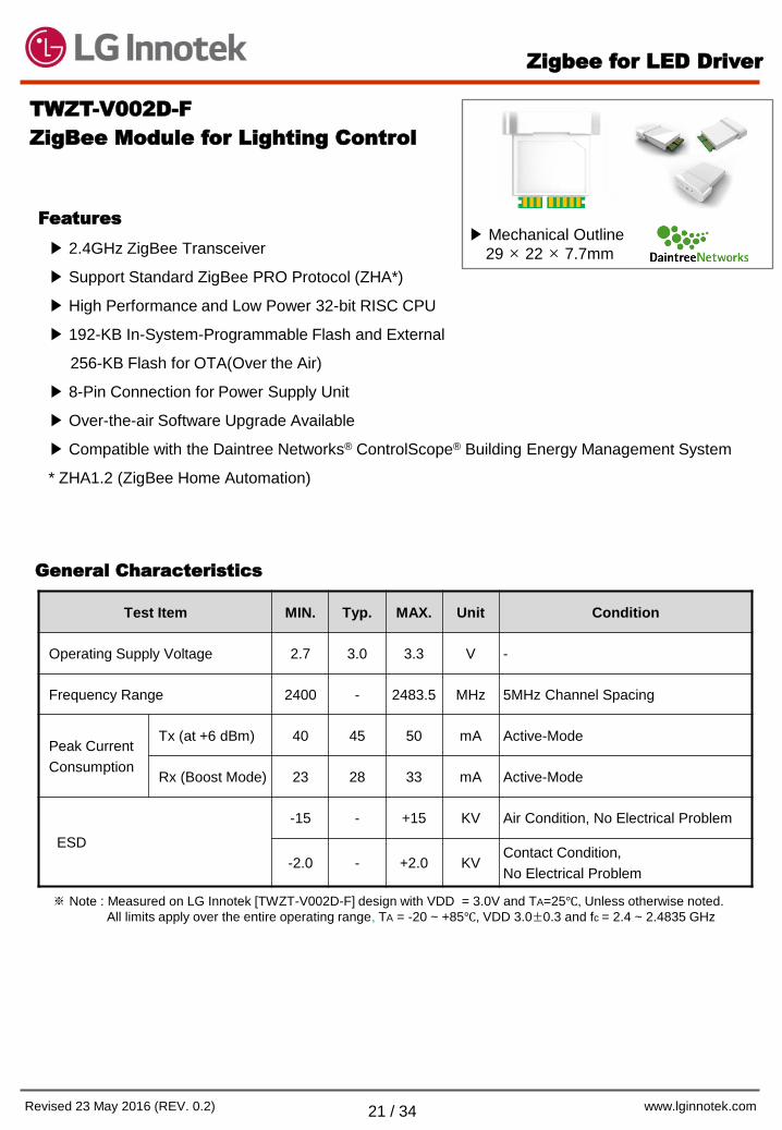
2.4GHz ZigBee Transceiver
Support Standard ZigBee PRO Protocol (ZHA*)
High Performance and Low Power 32-bit RISC CPU
192-KB In-System-Programmable Flash and External
256-KB Flash for OTA(Over the Air)
8-Pin Connection for Power Supply Unit
Over-the-air Software Upgrade Available
Compatible with the Daintree Networks® ControlScope® Building Energy Management System
* ZHA1.2 (ZigBee Home Automation)
Test Item MIN. Typ. MAX. Unit Condition
Operating Supply Voltage 2.7 3.0 3.3 V -
Frequency Range 2400 - 2483.5 MHz 5MHz Channel Spacing
Peak Current
Consumption
Tx (at +6 dBm) 40 45 50 mA Active-Mode
Rx (Boost Mode) 23 28 33 mA Active-Mode
ESD
-15 - +15 KV Air Condition, No Electrical Problem
-2.0 - +2.0 KV Contact Condition,
No Electrical Problem
TWZT-V002D-F
ZigBee Module for Lighting Control
Features
Mechanical Outline
29 × 22 × 7.7mm
General Characteristics
※ Note : Measured on LG Innotek [TWZT-V002D-F] design with VDD = 3.0V and TA=25, Unless otherwise noted.
All limits apply over the entire operating range, TA = -20 ~ +85, VDD 3.0±0.3 and fc = 2.4 ~ 2.4835 GHz
Zigbee for LED Driver
Page 22
LED Driver
www.lginnotek.com Revised 23 May 2016 (REV. 0.2) 22 / 34
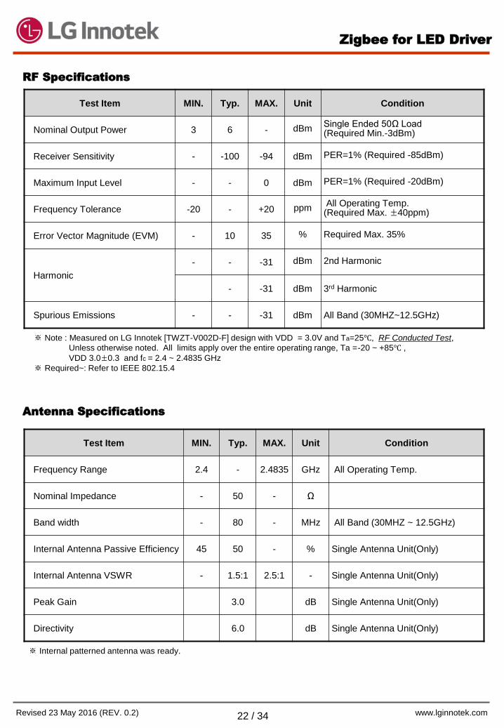
Test Item MIN. Typ. MAX. Unit Condition
Frequency Range 2.4 - 2.4835 GHz All Operating Temp.
Nominal Impedance - 50 - Ω
Band width - 80 - MHz All Band (30MHZ ~ 12.5GHz)
Internal Antenna Passive Efficiency 45 50 - % Single Antenna Unit(Only)
Internal Antenna VSWR - 1.5:1 2.5:1 - Single Antenna Unit(Only)
Peak Gain 3.0 dB Single Antenna Unit(Only)
Directivity 6.0 dB Single Antenna Unit(Only)
Antenna Specifications
※ Note : Measured on LG Innotek [TWZT-V002D-F] design with VDD = 3.0V and Ta=25, RF Conducted Test,
Unless otherwise noted. All limits apply over the entire operating range, Ta =-20 ~ +85 ,
VDD 3.0±0.3 and fc = 2.4 ~ 2.4835 GHz
※ Required~: Refer to IEEE 802.15.4
Test Item MIN. Typ. MAX. Unit Condition
Nominal Output Power 3 6 - dBm Single Ended 50Ω Load (Required Min.-3dBm)
Receiver Sensitivity - -100 -94 dBm PER=1% (Required -85dBm)
Maximum Input Level - - 0 dBm PER=1% (Required -20dBm)
Frequency Tolerance -20 - +20 ppm All Operating Temp. (Required Max. ±40ppm)
Error Vector Magnitude (EVM) - 10 35 % Required Max. 35%
Harmonic
- - -31 dBm 2nd Harmonic
- -31 dBm 3rd Harmonic
Spurious Emissions - - -31 dBm All Band (30MHZ~12.5GHz)
RF Specifications
Zigbee
※ Internal patterned antenna was ready.
Zigbee for LED Driver
Page 23
LED Driver
www.lginnotek.com Revised 23 May 2016 (REV. 0.2) 23 / 34
Mechanical Outline
1. Dimension
2. Pin Description
Pin No. I/O Pin Name Description
1 I MODE_SEL Normal Mode (High) / Test Mode (Low)
2 I/O DIM_SEL 10% Dim(High) / 5% Dim(Low)
3 - VDD Power Supply Typ. 3.0V (2.7V ~ 3.3V)
4 I UART_RX UART_RX
5 - GND Ground
6 O Dim Dimming Control
7 O UART_TX UART_TX
8 O On/off On/off Control
7.7
7.0
22.0
22.0
3.7
18.1
17.4
LED INDICATOR
Zigbee Zigbee for LED Driver
Page 24
LED Driver
www.lginnotek.com Revised 23 May 2016 (REV. 0.2) 24 / 34
PIHN-W005A
Wireless Interface Module
1-10V Dimming / On/Off
Mechanical Outline
- Plastic Case
210(L) × 30(W)
× 25(H)mm
※ Note : All parameters NOT specially mentioned are measured at rated load and 25 of ambient temperature.
Features
Specification Summary
Parameter Min. Typ. Max. Unit Remark
Input Voltage (Nominal) 120 - 277 Vac -
Input Voltage (Performance) 108 - 305 Vac -
Input Power - - 3 W -
AC Output Voltage 108 - 305 Vac Input Voltage (Nominal)
±10%
Nominal Input Frequency - 50/60 - Hz -
Load Rating - - 1.5 A @ 120~277VAC
Wireless Frequency Range 2.4 - 2.48 GHz ZigBee (ZHA1.1)
Transmitting Power - +7 - dBm Booster Mode
Dimming Output 1 - 10 V ZigBee PWM=10% to 100%
Dimming Sink Current - - 7 mA -
Applied Internal Load Switch to control AC main On/Off
Integrated AC-DC supply for stand-alone operation
Supports 1-10V Dimming
2.4GHz ZigBee® Transceiver
Supports Standard ZigBee PRO Protocol (ZHA)*
Embedded antenna for easy installation and low cost
Flexible platform to accommodate diverse protocols
UL 916, UL 60730-1, FCC Part 15 Certification Approved
RoHS Compliant
Compatible with the Daintree Networks® ControlScope® Building Energy Management System
Daintree Networks® and ControlScope® are registered trademarks of Daintree Networks.
ZigBee® is a registered trademark of the ZigBee Alliance.
Wireless Interface Module
Page 25
LED Driver
www.lginnotek.com Revised 23 May 2016 (REV. 0.2) 25 / 34
※ Note : All parameters NOT specially mentioned are measured at rated load and 25 of ambient temperature.
Environmental Specifications
Parameter Min. Typ. Max. Unit Remark
Temperature Operation -20 - 70 @ Ta
Storage -35 - 85 @ Ta
Humidity Operation 10 - 90 % -
Storage - - 95 % -
Lifetime 50 - - KHrs @ Ta=70
Parameter Condition Remark
Safety Standards Design to meet the requirements as follows ;
- UL 916, UL 60730-1
EMI / RFI
Standards
Design to meet the requirements as follows ;
- FCC Part 15, Class B verification
Standards
Wireless Interface Module
Page 26
LED Driver
www.lginnotek.com Revised 23 May 2016 (REV. 0.2) 26 / 34
Performance Curve
※ PWM Duty : ZigBee Control Duty
Dim. Voltage : 1-10 Output Voltage of Wireless Interface Module
Load Coverage (VAC - IAC Curve)
※ Notice
The WIM can not be protected when loads exceeding the load coverage are
connected to the WIM.
Then the WIM will be abnormal status like as heating or no operation.
Wireless Interface Module
Page 27
LED Driver
www.lginnotek.com Revised 23 May 2016 (REV. 0.2) 27 / 34
Mechanical Outline
1. Case Dimension
CTQ
M.P
CTQ
M.P
3D View
Wireless Interface Module
Page 28
LED Driver
www.lginnotek.com Revised 23 May 2016 (REV. 0.2) 28 / 34
Model PIHN-W005A Installation Instruction
The WIM model PIHN-W005A is an AC powered device that provides wireless adaptation and
control of On/Off switching and 1-10V analog dimming for LED drivers and electronic ballasts.
Specifications
Parameter Specification Remark
Input Voltage 120-277VAC, 50/60Hz -
Load Rating 1.5A max @120-277VAC -
Load Types Electronic Ballast, General Use LED
Driver -
Dimming Output 1-10VDC, 7mA max -
Radio Properties 2.4GHz, +7dBm Range dependent on the
RF environment
Operating Environment Indoor, dry location
-4 to +158 (-20 to +70) -
Compliance UL, FCC Part 15 -
Mounting Inside fixture, or enclosure -
Dimensions 1.18” W x 0.98” H x 8.27” L
(30mm W x 25mm H x 210mm L) -
ZigBee standard compliance ZHA -
Applied Internal Load Switch to control AC main On/Off
Integrated AC-DC supply for stand-alone operation
Supports 1-10V Dimming
2.4GHz ZigBee® Transceiver
Supports Standard ZigBee PRO Protocol (ZHA)*
Embedded antenna for easy installation and low cost
Flexible platform to accommodate diverse protocols
UL 916, UL 60730-1, FCC Part 15 Certification Approved
RoHS Compliant
Compatible with the Daintree Networks® ControlScope®
Building Energy Management System
Daintree Networks® and ControlScope® are registered trademarks of Daintree Networks.
ZigBee® is a registered trademark of the ZigBee Alliance.
Reset Button &
LED Indicator
Installation Instruction for
Wireless Interface Module
Page 29
LED Driver
www.lginnotek.com Revised 23 May 2016 (REV. 0.2) 29 / 34
Installation Process
1. Do not connect power to WIM before installation.
All power relating to the lighting fixtures and WIM has to be turned off by turning off circuit
breakers. Please confirm that power is off before installation.
2. Mount the WIM in the empty space of the fixture.
3. For dimming fixtures, connect DC low voltage wiring from the WIM to the LED Driver(s).
4. Connect AC line wiring from AC supply to the WIM.
5. Connect AC neutral from the AC supply to the WIM and to the LED Driver(s).
6. Connect AC load wire from the WIM to the LED Driver(s).
7. Check load circuits then turn on the circuit breakers to power up the WIM. The light fixtures
connected to the WIM turn On when power is initially applied.
8. Locate the Reset button on the WIM. It is on the dongle, inside the pinhole.
Insert the end of a paper clip in the pinhole, press and hold the button for 3 seconds.
Release the button when the blue LED inside the pinhole starts blinking.
The WIM is now reset to factory defaults, not joined to a ZigBee Network, the LED is Off.
LED Indicator
Mode LED Operation Description
Normal
Joined On
Powered and joined to a ZigBee
Network.
Normal when not
joined/after reset Off
Not powered, or powered but not joined
to a ZigBee Network
On/Off Test
(Test Mode)
Blink
On (0.3 sec), Off (1.5 sec)
(repeats)
The AC Line Voltage Load output
switches On, and Off.
Dimming Test
(Test Mode)
Double Blinks
On (0.25 sec), Off (0.25
sec)
twice, then Off (1.5 sec)
(repeats)
The Low Voltage Dimming output
operates to sweep the light between
minimum and maximum intensity.
Identify Device
(Normal)
Slow Blink
On (1 sec), Off (1 sec)
(repeats)
Identify mode while joined to a ZigBee
network.
The LED indicator can be seen through the pinhole on top of the dongle. When lit, it is blue.
Installation Instruction for
Wireless Interface Module
Page 30
LED Driver
www.lginnotek.com Revised 23 May 2016 (REV. 0.2) 30 / 34
Wiring
CLASS 2 WIRING: All field wiring shall be suitable for Class 1, Electric Light and Power, or
Class 2, 3 wirings are routed separately and secured to maintain separation between 1)
Class 2 wiring and all other class wiring, and 2) limited energy circuit conductors from
unlimited energy circuit conductors.
Disconnect all power before installation.
All installation and maintenance of line voltage equipment must be performed by a qualified electrician.
The WIM must be installed in accordance with all local, state, and national electrical codes and requirements.
Wiring connectors are not supplied. UL recognized wiring connectors must be used in the installation.
Each terminal can accept one conductor only. Connect only one 20~16AWG wire to any terminal.
CAUTION : Risk of electrical shock
Connection Diagram
Installation Instruction for
Wireless Interface Module
Page 31
LED Driver
www.lginnotek.com Revised 23 May 2016 (REV. 0.2) 31 / 34
Mount
The WIM is designed to be mounted inside a light fixture.
A barcode label with the WIM’s full IEEE address on it is included with the WIM.
This is the Fixture label. Affix this label to the outside of the fixture.
Choose a standard location so that when someone looks for fixtures containing a WIM
they will know where to look for the IEEE address bar code label.
Important Notices
Complete Installation Tests
Successful commissioning is dependent on testing each wireless-interfaced lighting
fixture and control device at the time of installation. Finding installation issues or device
problems earlier saves significant time during the commissioning process.
Record IEEE Addresses
If you have not already done so, be sure that each adapter’s IEEE address (last 4 or 5
digits) is recorded on the facility floor plan. You can use the 4 or 5 digit Plan label
supplied with the WIM or you can write the last 4 or 5 digits on the floor plan.
This information will be used during the commissioning process.
After the lighting installation is complete, a marked-up copy of the facility floor plan
showing the identity and location of each WIM (including associated fixtures) should be
available. This will simplify and expedite the commissioning process.
Installation Instruction for
Wireless Interface Module
Page 32
LED Driver
www.lginnotek.com Revised 23 May 2016 (REV. 0.2) 32 / 34
Installation Tests
All lighting devices, including WIM must be tested for proper operation.
After mounting, wiring low voltage, wiring line voltage, powering up and resetting the unit,
perform the recommended Installation Tests. The Installation Test mode automatically
times out after 5 minutes of no activity.
While the WIM is in Installation Test mode it directly controls lights wired to the same WIM.
After you exit Installation Test mode, the lights turn On. See the section “Joining the ZigBee
Lighting Control Network” for more information about how the WIM operates after
commissioning.
NOTE: The test mode can be initiated whether the WIM is currently joined or not joined to the
ZigBee Network. If it is already joined to the correct network and passes the necessary tests
(steps 1-3 below) do not perform step 4, since a reset causes the WIM to leave the ZigBee
Network.
Test Mode Process :
1. Momentarily press and release the reset button 1 time to activate the On/Off Test.
The blue LED starts blinking repeatedly [On (0.3 sec), Off (1.5 sec)] then lights begin
to cycle On, and Off.
2. Momentarily press and release the reset button 1 time again to activate the Dimming Test.
The blue LED starts double-blinking repeatedly [On (0.25 sec), Off (0.25 sec) twice,
then Off (1.5 sec)] then the lights operate to sweep between minimum and maximum
brightness.
3. Momentarily press the reset button 1 time again to terminate the Test Mode.
The blue LED is off, indicating the test mode is ended.
4. Press and hold the reset button on the WIM dongle for 3 seconds to reset the unit
Installation Instruction for
Wireless Interface Module
Page 33
LED Driver
www.lginnotek.com Revised 23 May 2016 (REV. 0.2) 33 / 34
Joining a ZigBee Network
After successfully completing the Installation Test, the WIM is ready to communicate with the
ZigBee coordinator, such as the Daintree Wireless Area Controller (WAC), a part of the
Daintree ControlScope wireless building controls system. Upon commissioning, the WIM’s
LED turns on solid and remains on as long as the WIM is included in the ZigBee Network.
After joining the network, depending on the zone and device configuration in the control
system, wireless signals from the ZigBee coordinator to the WIM determine the operation of
the light(s).
For more information about joining the ZigBee network, see the instructions provided by the
control system vendor.
Copyright. 2016. All Rights Reserved.
Installation Instruction for
Wireless Interface Module
Page 34
LED Driver
www.lginnotek.com Revised 23 May 2016 (REV. 0.2) 34 / 34
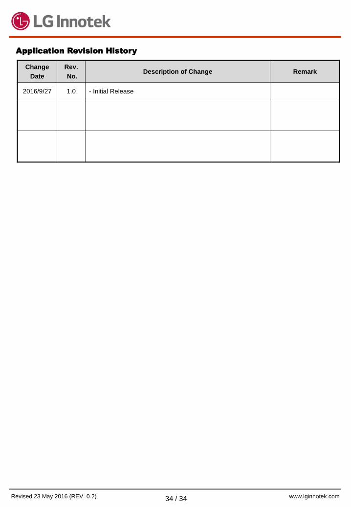
Application Revision History
Change
Date
Rev.
No. Description of Change Remark
2016/9/27 1.0 - Initial Release