LH2 Absorber R&D Shigeru Ishimoto (KEK) (1) 1st Test Results of KEK Absorber at MTA (2) Plan of 2nd Test of KEK Absorber at MTA (3) Mucool/MICE Absorber R&D MUTAC Meeting LBNL April 25-26, 2005
Transcript
LH2 Absorber R&D
Shigeru Ishimoto (KEK)
(1) 1st Test Results of KEK Absorber at MTA(2) Plan of 2nd Test of KEK Absorber at MTA (3) Mucool/MICE Absorber R&D
MUTAC MeetingLBNL
April 25-26, 2005
Forced Flow Type ~ 350 W
Mucool (FNAL)
Convection Type
Cooled by Cold He Flow ~ 50 W
Mucool (KEK, FNAL)
Cooled by “Cryocooler” ~ 10 W
MICE (KEK, RAL, Oxford)
Seal Method
Indium Mucool/MICE (FNAL, KEK)
Helicoflex MICE (KEK) --- back up
Welding MICE (Oxford) --- back up
LH2 Absorber R&D
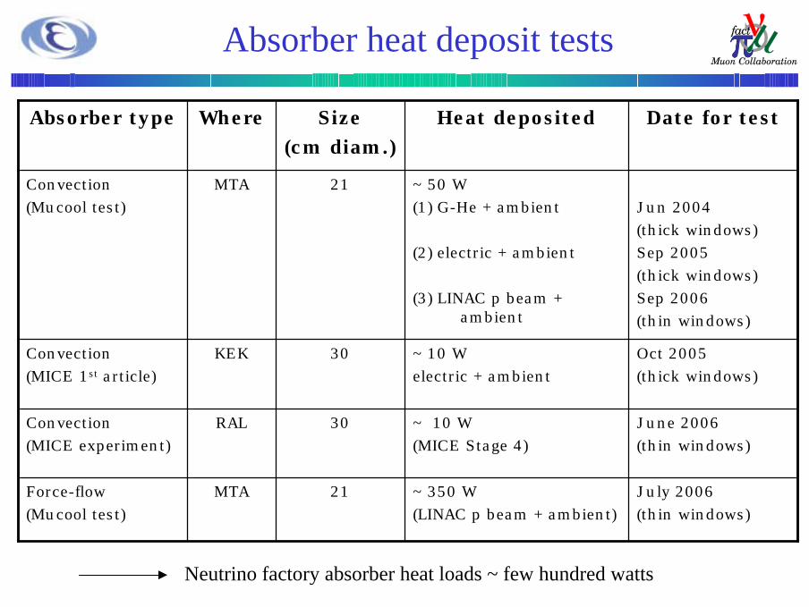
Neutrino factory absorber heat loads ~ few hundred watts
MTA
RAL
KEK
MTA
Where
June 2006 (thin windows)
~ 10 W(MICE Stage 4)
30Convection(MICE experiment)
July 2006(thin windows)
~ 350 W(LINAC p beam + ambient)
21Force-flow(Mucool test)
Oct 2005(thick windows)
~ 10 Welectric + ambient
30Convection(MICE 1st article)
Jun 2004(thick windows)Sep 2005(thick windows)Sep 2006(thin windows)
~ 50 W(1) G-He + ambient
(2) electric + ambient
(3) LINAC p beam + ambient
21Convection(Mucool test)
Date for testHeat depositedSize (cm diam.)
Absorber type
Absorber heat deposit tests
1st Test of KEK Absorber at MTA
G-He HeaterPtCo #1 - #8
V=6.2 L
D=200, L=200
PtCo He-IN
PtCoW-He-OUT(center)
PtCo W-He-OUT (bottom)
W-He-IN (bottom)
W-H2-IN/OUT
C-He-OUT
1st Test of KEK Absorber at MTA
1st Test of KEK Absorber at MTA
Set-up of absorber test cryostat
Top flange of absorber test cryostat
Electric cabinet purged by G-N2
1st Test of KEK Absorber at MTA
Valve Box
Heater
Transfer tubes
Thermometer
1st Test of KEK Absorber at MTA
Equivalent Hydrogen
Normal Hydrogen (Ortho-75%, Para-25%)
<Limits of L-H2 Temperature and Pressure>*Tmin > 13.8 K; no solid-H2 to avoid blocking*Ta < 22.2 K, P < 1.7 bar; from the operation pressure, Pmax=2.5 bar*Ta > 20.4 K, P > 1.05 bar; over pressure than atmosphere
L-H2 Control
8.4 K
Thermal OscillationT_abs = 22~30 K
T_abs
T_HeIN
T_HeOUT T_R.S
1 hr
Test Results of KEK Absorber at MTA
Test Results of KEK Absorber at MTA
Q = 0 W Data
Test Results of KEK Absorber at MTA
Test Results of KEK Absorber at MTA
KEK LH2 absorber test - Evolution of LH2 temperature gradient versus applied power(with +/- 5% error)
0.0
0.2
0.4
0.6
0.8
1.0
1.2
1.4
1.6
1.8
2.0
2.2
2.4
2.6
2.8
0.0 5.0 10.0 15.0 20.0 25.0
Power applied to the LH2 absorber (W)
Del
ta T
(K)
19.518.416.318.016.418.815.415.1
線形 (16.3)線形 (15.4)
dT=2.45K at 22.1W if dT=8.4K then 77W ?( Tmax=22.2K, Tmin=13.8K )
Expected cooling power from 1st test
Test Results of KEK Absorber at MTA
and Plan for the 2nd Test
Test results of the 1st cooling test(1) Succeed the 1st absorber cooling test with full LH2.
No H2 leak to vacuum was found. (2) Succeed to stabilize the cold helium gas flow(3) Measured the LH2 temperature distribution in absorber.(4) Measured the cooling power with G-He heater until ~22W.
Plan for the 2nd cooling testAim; Test the maximum cooling power by tuned condition
(1) Short cut the LHe-transfer line to reduce the heat-leak and stabilize the flow and temperature.
(2) Change the G-He heater to an electric heater (3) 4 wired Cernox thermometers(4) L-H2 level sensor
Plan of the 2nd Absorber Test at MTA
Lake Shore HTR-25-100
Lake Shore CX-1050-SD
DC ~mA
V4
V3
DC Current for L-H2/LHe should be optimized (KEK R&D).
LHeLH2
Plan of the 2nd Absorber Test at MTA
Plan of the 2nd Absorber Test at MTA
L-H2 LevelSensor
8Cernox
Lake Shore 218
Keithley2700
2- DC-PS
PC
G-N2 purge
Heater
100W- DC-PS
(3) Mucool/MICE Absorber R&D
CryocoolerRDK-415D
LH2
LH2
MICE absorber system with Cryocooler
He refrigerator
Exit to cool the transfer tube
G-H2 cylinders/H2 tank/ Metal hydride
G-H2 safety exit and reservoir tank
He, N2 gas exit/return
H2 leak monitor
L-He Dewar
L-N2 Dewar
G-He cylinders
Absorber vacuum system
Safety exit for H2
L-H2 Level Sensor
MICE Absorber
Thermometers
2-Heaters
L-H2 IN
L-H2 OUT
Lake Shore HTR-25-100
Lake Shore CX-1050-SD
Room Temp. Magnet Bore
MICECryocooler RDK-415D
MICE 1st Absorber
Mucool/MICE Absorber Test Cryostat at KEK
Mucool/MICE Absorber Test at KEK
Cryocooler
Cryostat for thermometer/LH2 level sensor calibration
Mucool/MICE Absorber Test Cryostat
KEK East Counter Hall
Cryocooler
Hydrogen System Baseline layout (RAL)
Pressuregauge
Non-returnvalve
-P P VP Vacuum pumpBursting diskPressure
relief valveValvePressure
CoolantOut In
Metal Hydride storage unit
(20m3 capacity)
Purge valve
0.5 bar
0.9 bar
H2 Detector
P
P
VP1
VP2
Purge valve
Chiller/Heater Unit
1 bar
PP
0.5 bar
0.9 bar Helium supply
Hydrogen supply
High level vent
Buffer vessel
Vent outsideflame arrester
Extract hoodH2Detector
PP
Nitrogen supply
PP
PP
1 m3
Hydrogen zone 2
Vent manifold Vent manifold
P1
PV1
PV7
PV8
PV2
PV3
PV4
HV1
Fill valve
Tbed
HV2
HV3
P3
PP2
PV6
High level vent
Non returnvalve
0.1 bar
-P P VP Vacuum pumpBursting diskPressure
relief valveValvePressureregulator
CoolantOut In
Absorber window
Metal Hydride storage unit
(20m3 capacity)
Purge valve
0.5 bar
0.9 bar
H2 DetectorH2 Detector
P
P
VP1
VP2
Purge valve
Chiller/Heater Unit
1 bar
PP
0.5 bar
0.9 bar Helium supply
Hydrogen supply
High level vent
Buffer vessel
Vent outsideflame arrester
Extract hoodH2DetectorH2Detector
PP
Nitrogen supply
PP
PP
1 m3
Hydrogen zone 2
Vent manifold Vent manifold
P1
PV1
PV7
PV8
PV2
PV3
PV4
HV1
Fill valve
Tbed
HV2
HV3
P3
PP2
PV6
High level vent
Non returnvalve
0.1 bar
Safety window
R&D Test Cryostat (RAL)
T H
T H
•Instrumentation mimics what we will need on the absorber for the control system and interlocks
•Heater will regulate temperature of cryocooler –need redundancy and interlock with compressor
•Dia. reservoir=height=290mm
Summary
(1) 1st Test Results of KEK Absorber at MTA*First absorber test with full LH2*No H2 leak by Indium seal*Learned a lot
(2) Plan of 2nd Test of KEK Absorber at MTA*Discussion and preparation are going*L-He transfer tube, electric heater, thermometer, DAQ
will be modified.*We will try higher power as much as possible.
(3) Mucool/MICE Absorber R&D*MICE Absorber with Cryocooler design was almost fix*MICE Absorber R&D is going at KEK and RAL