LHC Projec CERN Div./Group or Suppli t Document No. LHC-BI-ES-XXXX.XX rev 1.0 Draft er/Contractor Document No. SL/BI EDMS Document No. - Date: 2001-11-0830 the Large Hadron Collider project CERN CH-1211 Geneva 23 Switzerland ENGINEERING SPECIFICATIONS BOBR THE BEAM SYNCHRONOUS TIMING RECEIVER INTERFACE FOR THE BEAM OBSERVATION SYSTEM. Abstract Beam Synchronous Timing (BST) is required for beam instrumentation in the LHC accelerator chain. The Timing, Trigger and Control (TTC) system, designed for LHC detectors, provides a way of distributing the different 40MHz bunch clocks and Orbit turn clocks from the Prevessin Control Room (PCR) to the LHC experiment areas and to beam instrumentation around the ring and in the transfer lines through different networks. In addition we profit from the TTC's ability to transmit data by inserting a BST message which can be broadcasted to all instrumentation crates throughout the TTC distribution networks. The Beam synchronous timing Receiver interface for Beam Observation system (BOBR) acts as an interface between the TTC distribution network and its receiving end users. The BOBR is designed to recover the 2 distributed clocks, decode and store all BST messages and make them available to the front-end electronics controllers. The BOBR is a VME format card, designed to interface a VME crate with up to 2 different TTC networks, and provid all timing signals required to synchronize the different beam instrumentation systems. This document is intended to provide a functional and physical description of the BOBR for the end user. Prepared by: Jean-Jaques SAVIOZ [SL/CERN] [email protected]Checked by:
Beam Synchronous Timing (BST) is required for beam instrumentation in the LHC accelerator chain.
The Timing, Trigger and Control (TTC) system, designed for LHC detectors, provides a way of distributing the different 40MHz bunch clocks and Orbit turn clocks from the Prevessin Control Room (PCR) to the LHC experiment areas and to beam instrumentation around the ring and in the transfer lines through different networks. In addition we profit from the TTC's ability to transmit data by inserting a BST message which can be broadcasted to all instrumentation crates throughout the TTC distribution networks.
The Beam synchronous timing Receiver interface for Beam Observation system (BOBR) acts as an interface between the TTC distribution network and its receiving end users. The BOBR is designed to recover the 2 distributed clocks, decode and store all BST messages and make them available to the front-end electronics controllers.
The BOBR is a VME format card, designed to interface a VME crate with up to 2 different TTC networks, and provid all timing signals required to synchronize the different beam instrumentation systems.
This document is intended to provide a functional and physical description of the BOBR for the end user.
1. INTRODUCTION Beam Synchronous Timing (BST) is required for beam instrumentation in the LHC accelerator chain.[1]
The Timing, Trigger and Control (TTC) system[2], designed for LHC detectors, provides a way of distributing the 3 different 40MHz bunch clocks and Orbit turn clocks from the Prevessin Control Room (PCR) to the LHC experiment areas and to beam instrumentation around the ring and in the transfer lines through 3 different networks. In addition we profit from the TTC's ability to transmit data by inserting a BST message which can be broadcasted to all instrumentation crates throughout the TTC distribution networks.
The Beam synchronous timing Receiver interface for Beam Observation system (BOBR) acts as an interface between the TTC distribution network and its receiving end users. The BOBR is designed to recover the 2 distributed clocks, decode and store all BST messages and make them available to the front-end electronics controllers.
The BOBR is a VME64x[4] format card, designed to interface a VME crate with up to 2 different TTC networks, and provid all timing signals required to synchronize the different beam instrumentation systems.
This document is intended to provide a functional and physical description of the BOBR for the end user
2. TTC SYSTEM OVERVIEW
The Timing, Trigger and Control (TTC) system for LHC detectors has been specified and a complete description of the system and its functionality can be found in reference [2]. However, a brief overview of the TTC system features that are relevant for the understanding and utilisation of the BOBR is given here. The TTC system provides the distribution of all signals necessary to synchronise the detectors: clock, trigger, and arbitrary control data, which are all distributed on a single optical fibre. The distribution is synchronous to the LHC bunch structure. Figure 2 illustrates the basic architecture of the TTC system. At the top of the TTC tree structure, two communication channels are Time Division Multiplexed (TDM), BiPhase Mark (BPM) encoded and transmitted over a passive optical fibre distribution network using a single laser source. One of the TDM channels (channel A) is exclusively dedicated to broadcast a global trigger. In our case, this feature is used to send the orbit turn clock by setting this bit high every time the beam completes a revolution of the machine. Channel B is used to broadcast data to all or specific system destinations. Data in channel B can be of two types: broadcast commands or individually addressed commands/data. Broadcast commands will be used to distribute the BST messages to all TTC destinations in the system. The TTC system is also used to distribute the LHC 40.08 MHz bunch-crossing reference clock signal. This signal is not explicitly transmitted over the network and has to be recovered from the incoming frame at each TTC destination. The CERN Microelectronics Group has developed a TTC receiver ASIC (TTCrx) [5] which delivers the TTC signals to the front-end controllers. The TTCrx can deliver the full range of decoded and deskewed signals, including all received synchronous commands. The commands/data are implemented in the system to transmit user-defined data and commands over the network. These commands have two distinct modes of operation. In the first mode, they are aimed at the TTCrx themselves and their user-defined content can be used to control the receiver chip’s operation. In the second mode, the data is intended for the external electronics. In this case, both the data and sub-address contents of the received commands are externally available.
2.1 TTC frame format Both the broadcast and the individually addressed commands are transmitted over the TTC network
using a frame format that has been specified in reference [2] and which is schematically represented in Figure 3. The frame structure contains several fields to control the transmission, and includes a field in which several redundant bits are inserted for error detection and correction. The coding scheme used is a standard Hamming code with the capability of double error detection and single bit error correction. The error correction coding covers the 8-bit data word in the case of a short frame and the 32-bit data in the case of a long frame. A broadcast of a long frame can be performed by setting the TTCrx address equal to zero. The address space selection bit (E) instructs the addressed TTC receiver either to execute an internal operation or to make the received command/data externally available. Using this scheme it is possible to address up to 256 internal and external sub-addresses. Each frame is identified by a header bit (FMT) that indicates its type. Start (logical “0”) and stop (logical “1”) bits are always included at the beginning and end of the frame transmission to facilitate correct synchronisation.
- 40.08MHz clock - Global trigger - Bunch counter reset - Bunch crossing number - Event counter reset - Event number - Broadcast commands - Subaddress - Addressed commands
TTCrx
Figure 2: TTC distribution network
General TTC frame: 1 0
IDLE START FMT COMMANDS/DATA CHCK STOP
Short format Broadcast Commands/Data:
Long format Broadcast or Individually-Addressed Commands/Data:
0 0 8b CMD/DATA 5b CHCK 1
0 1 14b TTCrx ADDR E 8b SUBADDR 8b DATA 7b CHCK 1
Figure 3 : TTC Data Transmission frame
LHC Project Document No.
LHC-BI-ES-XXXX.XX rev 1.0 Draft
Page 7 of 23
3. BST SYSTEM OVERVIEW
The beam synchronous timing system for LHC beam instrumentation serves to synchronise acquisitions in areas that are very distant geographically, and is also used to convey signals, parameters and commands simultaneously to all instruments around the machine. All necessary real-time information is regrouped and transmitted in a so-called BST message. The complete BST system consists of: a BST Master, used to broadcast the synchronisation signals and the BST messages; the TTC system, used to encode and transmit the signals; a receiver interface, the BOBR, installed in each beam instrumentation crates recovers the BST messages and provides all timing signals required to synchronize the acquisition systems. A real-time process called the BST message assembler collects all the data and commands to be transmitted via the TTC system on a given turn. These data and commands are then assembled into a message of a predefined number of bytes. At each orbit turn clock period, the BST Master transmits the message for the current turn over channel B of the TTC system. In total, three operational BST systems and TTC networks are required, one for each of the LHC rings and another for the SPS ring and its transfer lines. Separate systems are needed since the revolution frequencies (and hence the bunch clock and turn clock) of all three are or can be different.
BST
MESSAGE
ASSEMBLER
TTC
Encoder&
Optical Transmit.
Bunch & Turn Clocks
TTC Optical Network
BOBR
BST MESSAGE RECEIVER Data
Bytes
TTCrx
Clocks
MESS 1
Data Bytes MESS 0
MESS 2
Data Bytes MESS 1
MESS 3
MESS 2 MESS 1MESS 0
t
MESS 0 MESS 1 MESS 2
Period = 88.9 µs (LHC) ; 23.1 µs (SPS)
Figure 4 : Basic architecture and transmission sequence of BST Messages
Phase adjustmen
ORBIT TURN CLOCK MESSAGE ASSEMBLER PROCESS TTC SERIAL TRANSMISSION TRANSMISSION DELAY CLOCKS & DATA MESSAGE RECOVERY LOCAL DELAYADJUSTMENT
TO B.I. End user
Universal time
Machine Events
Beam
Parameters
Real-time commands
Hardware triggers
LHC Project Document No.
LHC-BI-ES-XXXX.XX rev 1.0 Draft
Page 8 of 23
3.1 BST Message CONTENTS
The size of the BST message is limited by several physical parameters such as the serial output bandwidth and the duration of message assembly process. A message of 32 Long format Commands/Data can cover all beam instrumentation needs. The 8-bit sub-address allows 256 identified bytes of data to be sent. Table 1 defines the contents of each byte and its update frequency. This table is subject to change according to LHC operation or end users requirements.
Bytes Description Data format Updated every
0 Machine Mode Enumerated type: No beam, filling, ramping, physic,… On change1 Beam Type Enumerated type: Ion, Proton,… On change2 Beam Energy 2 bytes in GEV On change3 Beam Energy4 Mean Current per Bunch 2 Bytes * 10E11 ppp5 Mean Current per Bunch6 Number of injected Bunches 2 Bytes integer On change7 Number of injected Bunches8 Next Batch to Inject 0 for no beam or 1 .. 12 On change9 GPS Absolute Time 64 bits UTC format On change
10 GPS Absolute Time11 GPS Absolute Time12 GPS Absolute Time13 GPS Absolute Time14 GPS Absolute Time15 GPS Absolute Time16 GPS Absolute Time17 Last Machine Timing Event 2 Bytes : Machine Timing Event number On reception18 Last Machine Timing Event19 BI Predefined received Events 2 bytes : corresponding to 16 predefined events table On reception20 BI Predefined received Events21 Main Trigger Byte 8 X 1 bit dedicated Trigger: warning injection, start post-mortem, 1 Turn22 BI devices dedicated Bytes 10 Bytes device dedicated commands or triggers : 1 Turn23 BI devices dedicated Bytes Closed orbit capture, Single Turn trajectory measurement,….24 BI devices dedicated Bytes25 BI devices dedicated Bytes26 BI devices dedicated Bytes27 BI devices dedicated Bytes28 BI devices dedicated Bytes29 BI devices dedicated Bytes30 BI devices dedicated Bytes31 BI devices dedicated Bytes
Bytes 0 to 20 (the data in blue) come from the slow timing interface [7] where a time granularity of 1ms is adequate. Bytes 21 to 31(the data in green), where a time granularity of 1 turn is required, come either from an external trigger (e.g. an injection warning) or a demand from an operator application process (e.g. a closed orbit acquisition). There is also a possibility of inserting a time stamp to allow the clear identification of measurements.
4. BOBR OVERVIEW
The BOBR is another key component of the BST system. It has the task of interfacing the TTC system with the beam instrumentation, and is found at the end of the TTC distribution network.
A VME64x [4] format has been chosen for the BOBR, allowing it to be plugged into VME crate. All beam instrumentation applications will be based on a standard VME crate, and the BOBR will therefore reside on a dedicated VME slot, giving a direct connection of hardware signals to the VME P0 user I/O connector. The BOBR is built using the TTC receiver mezzanine (TTCrm) [5] and the basic features of the card depend on the TTC receiver Asic chip (TTCrx) [5].
LHC Project Document No.
LHC-BI-ES-XXXX.XX rev 1.0 Draft
Page 9 of 23
In addition to delivering the timing signals, the BOBR is used to handle the delivery of BST messages to the local CPU. The received messages are stored in a dual ported memory, which is accessible, together with all control registers, from the CPU via a specific VME interface.
A local pattern generator can provide 8 output signals with a granularity of 25 NS. Synchronized with the received timing signals in order to be used as bunch selector. All the BST Receiver control logic is put in an FPGA with the possibility of being reprogrammed. In order to reduce the number of VME crates, the BOBR is a dual BST Receiver, able to synchronise two sets of acquisition boards connected to one or two TTC networks.
An I2C Bus [10] interface and a JTAG [11] interface are include in the BOBR features. As it is not foreseen to install beam instrumentation controllers in irradiated areas, the BOBR
is not made with radiation-hard materials.
5. FUNCTIONAL DESCRIPTION
5.1 ARCHITECHTURE
Figure 5 shows the architecture of the BOBR. And Figure 6 shows the details of the BSTR part.
TTCrm: The incoming optical frame is converted into a differential signal by a photodiode with
integrated pre-amplifier. The TTCrx recovers the 40MHz LHC reference clock with minimum jitter, and can deskew it in steps of 104ps. The recovery circuit extracts the data stream and de-multiplexes the two channels. Channel A is identified as a Level 1 Trigger and an Event Counter is incremented each time it occurs. The data in channel B is fed into a serial to parallel converter, which decodes and sends out the two supported data formats (broadcast or individually addressed message). A hamming error detection/correction circuit can detect double bit errors, and correct single bit errors. An I2C interface is used to allow read/write accesses to all internal registers, the status of which can be read directly from the VME bus interface. An optional PROM can be use to load pre-defined register values after a reset.
VME Bus Interface: The VME64x standard is described in reference [4]. The board is configured as a direct 32 bit local bus to access the 2 BSTR FPGAs, and an 8 bit local bus is used to access two chips controlled by a dedicated EPLD:
1) The PCF8584 [9] I2C bus controller, which serves as an interface between the parallel local bus and the serial I2C bus for bi-directional connection with the internal registers of the TTCrx chips. The control of the I2C bus specific sequences, protocol and timing can be found in reference [10].
2) The SN74LVT8980[12] Embedded Test-Bus Controllers IEEE STD 1149.1 (JTAG) TAP Masters With 8-Bit Host Interface, which serves as an interface between the parallel local bus and the crate Multidrop Test and Maintenance Bus (MTMB).
The JATG interface includes a SCANPSC110F [11] SCAN Bridge, connected to the MTM Bus to perform in-situ FPGA programming and board testing over 3 local JTAG chains.
LHC Project Document No.
LHC-BI-ES-XXXX.XX rev 1.0 Draft
Page 11 of 23
For test and debugging purposes, 4 front panel indicator LEDs gives an overview of the Interfaces status, and control signals detailed in section 5.3 are routed to a test connector where a logic state analyser such as the HP16500 series can be attached.
The 2 BSTR FPGAs, where all logic functions are implemented. On reboot, the FPGA configuration is downloaded from a Flash RAM, which is itself in-situ programmable using a Boundary-Scan (JTAG port) [11]. All signals from the TTCRx, local bus, output connections, front panel LEDs and diagnostics are routed to the FPGA I/O ports.. The 2 BSTR FPGAs are identicaly designed with the following functionality:
• All received data bytes from the TTCrx are written in the corresponding sub-address of a dual-ported RAM. In addition, and on request, the next received message can be stored in an auxiliary dual-ported RAM accessible by the local controller and over written only on the next request.
• The 24-bit turn clock event counter delivered by the TTCrx is recorded at the beginning of each turn clock period in order to be read by the local controller together with the RAM contents.
• The TTCrx chip has only a 0 to 375ns coarse delay range. This is insufficient to compensate for the time of flight of particles to different locations around the accelerators. Hence a local turn clock delay has been added to allow a 25 ns step delay of up to 88.9µs for the LHC and up to 23.1µs for the SPS, corresponding to one revolution period respectively in each machine.
• Two Data Bytes can be routed to the hardware output signals. Either among the received data byte selected by its sub-address , called "hardware" bytes. The two selected bytes are sent to the hardware output together with the two main clocks (bunch and turn clocks), synchronous with the rising edge of the Local Delayed Turn Clock. Four control registers are used to define the mode and sub-addresses of the data bytes to be sent.
• A local pattern generator can provide 8 output signals or a bunch selector byte sequence pre-defined in a bunch selector RAM. This sequence has a granularity of 25ns (bunch selection) and can be enable or disable either by the local controller or by a received Data Byte selected by its sub-address.
• 8-bit mask registers are used to control interrupt generation to the local controller. Two of these masks are used to identify the two possible sub-addresses at which the data which will generate the interrupt is to be found. Each of these sub-addresses then has its own specific data mask to generate the interrupt. An interrupt will be generated if at least one of the bits of the mask is present in the data byte of a received command corresponding to the appropriate sub-address. When an interrupt is generated, the overwriting of dual port memory is stopped after storing the current message, and is only restarted after the message has been read.
• Three 16-bit counters are used to record single-bit, double-bit and transmission errors detected by the TTCrx. In case of double-bit or transmission detection, the corresponding command is rejected.
• In the absence of the optical signal, an internal Message Generator can locally simulate a sequence of up to 32 preloaded commands with the associated timing signals. The sequence can be generated either once (Single-shot mode) or on every simulated local turn clock (Repetitive mode).
• A global control / status register, detailed in section 5.5, allows the remote control of the BSTR. • The front panel, detailed in section 5.6, regroups three main signals used for debugging and 8
indicator LEDs, to give an overview of the BSTR status. • For test and debugging purposes, a clock and 16 control signals are routed to a test connector
where a logic state analyser such as the HP16500 series can be attached.
The Hardware Output Signal Control consists of a multiplexer implemented in an EPLD witch allows to select among the signals from the 2 BSTR FPGAs to be passed on the connector P0 divided into 2 identical sets. The selection is defined in the global control register detailed in section 8.1.
The standard 5 Volts and 3.3 Volts powers are supplied from the VME64x P1 connector.
LHC Project Document No.
LHC-BI-ES-XXXX.XX rev 1.0 Draft
Page 12 of 23
5.2 OVERALL FEATURES • VME64x[4] standard board with Mechanical support for electromagnetic
compatibility (EMC) control and electrostatic discharge (ESD) control.
• Provides Beam Synchronous Timing for 2 sets of system of both the LHC or SPS accelerators. • Interface with 1 or 2 TTC networks by using 1 or 2 TTC receiver mezzanine cards (TTCrm)[5]. • Supplies the 40.08 MHz Bunch Clock, which remains synchronous with the bunch structure. • Supplies the Local Turn Clock, corresponding to the orbit frequency. Locked either at 1/924 of
the bunch frequency for SPS or 1/3564 of the bunch frequency for LHC. • Local delays provide Local Clocks with the appropriate phase relative to the beam structure,
taking into account the difference between particle time-of-flight and signal propagation. • The overall jitter of the received clocks anywhere around the rings is less than 1ns rms. • A BST message consists of 32 BST commands within the 88.9 µs of an LHC period or up to 8
BST commands within the 23.1 µs of an SPS period. • A BST command contains 2 bytes: a sub address or identifier, and its associated data byte. • All the received commands are stored in a dual-ported RAM accessible by the local controller. • Supplies 16 output hardware signals corresponding to the received data byte
selected by its sub-address. • Supplies 8 output hardware signals corresponding to data stored into a local RAM and
defined as a bunch selector byte sequence. The content of the bunch selector RAM corresponds to 3564 slots of 25 ns.
• BOBR uses 256 bytes of VME I/O space for global control registers, I2C and JTAG interfaces. And 16 Kbytes of VME Memory space for each BSTR for all control registers and RAMs.
• A VME interrupt request can be generated on reception of a specific message or on error. • A local clock signal generator and up to 32 byte BST command message generator allows the
BOBR module to run in stand-alone mode for test purposes. • Optical Input Connectors are ST type receptacle, with optical dynamic range from –25 dBm to
–5 dBm. • Main timing signals outputs and indicator leds are available on the front panel for diagnostics. • All output signals are available on the 95-pin VME P0 I/O connector. • The FPGA's configuration is designed using VHDL code [11], giving the maximum of flexibility
for satisfying future requirements.
LHC Project Document No.
LHC-BI-ES-XXXX.XX rev 1.0 Draft
Page 13 of 23
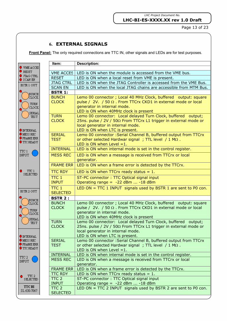
6. EXTERNAL SIGNALS
Front Panel: The only required connections are TTC IN, other signals and LEDs are for test purposes.
Item: Description:
VME ACCES LED is ON when the module is accessed from the VME bus. RESET LED is ON when a local reset from VME is present. JTAG CTRL LED is ON when the JTAG Controller is accessed from the VME Bus. SCAN EN LED is ON when the local JTAG chains are accessible from MTM Bus. BSTR 1: BUNCH CLOCK
Lemo 00 connector ; Local 40 MHz Clock, buffered output: square pulse / 2V. / 50 Ω . From TTCrx CKD1 in external mode or local generator in internal mode. LED is ON when 40MHz clock is present
TURN CLOCK
Lemo 00 connector: Local delayed Turn Clock, buffered output; 25ns. pulse / 2V / 50Ω From TTCrx L1 trigger in external mode or local generator in internal mode. LED is ON when LTC is present.
SERIAL TEST
Lemo 00 connector :Serial Channel B, buffered output from TTCrx or other selected Hardwar signal ; TTL level / 1 MΩ . LED is ON when Level =1.
INTERNAL LED is ON when internal mode is set in the control register.
MESS REC LED is ON when a message is received from TTCrx or local generator.
FRAME ERR LED is ON when a frame error is detected by the TTCrx.
TTC RDY LED is ON when TTCrx ready status = 1.
TTC 1 INPUT
ST-PC connector : TTC Optical signal input Operating range = -22 dBm ... -18 dBm
TTC 1 SELECTED
LED ON = TTC 1 INPUT signals used by BSTR 1 are sent to P0 con.
BSTR 2 : BUNCH CLOCK
Lemo 00 connector ; Local 40 MHz Clock, buffered output: square pulse / 2V. / 50 Ω . From TTCrx CKD1 in external mode or local generator in internal mode. LED is ON when 40MHz clock is present
TURN CLOCK
Lemo 00 connector: Local delayed Turn Clock, buffered output; 25ns. pulse / 2V / 50Ω From TTCrx L1 trigger in external mode or local generator in internal mode. LED is ON when LTC is present.
SERIAL TEST
Lemo 00 connector :Serial Channel B, buffered output from TTCrx or other selected Hardwar signal ; TTL level / 1 MΩ . LED is ON when Level =1.
INTERNAL LED is ON when internal mode is set in the control register. MESS REC LED is ON when a message is received from TTCrx or local
generator. FRAME ERR LED is ON when a frame error is detected by the TTCrx. TTC RDY LED is ON when TTCrx ready status = 1. TTC 2 INPUT
ST-PC connector : TTC Optical signal input Operating range = -22 dBm ... -18 dBm
TTC 2 SELECTED
LED ON = TTC 2 INPUT signals used by BSTR 2 are sent to P0 con.
LHC Project Document No.
LHC-BI-ES-XXXX.XX rev 1.0 Draft
Page 14 of 23 Hardware connector: All output Timing Signals are rooted to the VME P0 connector: Rows a & b for set 1, Rows d & e for set 2. Rows z & f are connected to GND. All other pins are not connected.
Pos Row a Row b Row c Row d Row e 1 HW Low Byte 1 bit 0 HW High Byte 1 bit 0 HW Low Byte 2 bit 0 HW High Byte 2 bit 0 2 HW Low Byte 1 bit 1 HW High Byte 1 bit 1 HW Low Byte 2 bit 1 HW High Byte 2 bit 1 3 HW Low Byte 1 bit 2 HW High Byte 1 bit 2 HW Low Byte 2 bit 2 HW High Byte 2 bit 2 4 HW Low Byte 1 bit 3 HW High Byte 1 bit 3 HW Low Byte 2 bit 3 HW High Byte 2 bit 3 5 HW Low Byte 1 bit 4 HW High Byte 1 bit 4 HW Low Byte 2 bit 4 HW High Byte 2 bit 4 6 HW Low Byte 1 bit 5 HW High Byte 1 bit 5 HW Low Byte 2 bit 5 HW High Byte 2 bit 5 7 HW Low Byte 1 bit 6 HW High Byte 1 bit 6 HW Low Byte 2 bit 6 HW High Byte 2 bit 6 8 HW Low Byte 1 bit 7 HW High Byte 1 bit 7 HW Low Byte 2 bit 7 HW High Byte 2 bit 7 9 10 11 12 Bunch Select 1 Bit 0 LVDS Turn clock Delay 1 + Bunch Select 2 Bit 0 LVDS Turn clock Delay 2 + 13 Bunch Select 1 Bit 1 LVDS Turn clock Delay 1 - Bunch Select 2 Bit 1 LVDS Turn clock Delay 2 - 14 Bunch Select 1 Bit 2 TTL Turn clock Delay 1 + Bunch Select 2 Bit 2 TTL Turn clock Delay 2 + 15 Bunch Select 1 Bit 3 TTL Turn clock Delay 1 - Bunch Select 2 Bit 3 TTL Turn clock Delay 2 - 16 Bunch Select 1 Bit 4 LVDS 40 MHz Clock 1 + Bunch Select 2 Bit 4 LVDS 40 MHz Clock 2 + 17 Bunch Select 1 Bit 5 LVDS 40 MHz Clock 1 - Bunch Select 2 Bit 5 LVDS 40 MHz Clock 2 - 18 Bunch Select 1 Bit 6 TTL 40 MHz Clock 1 + Bunch Select 2 Bit 6 TTL 40 MHz Clock 2 + 19 Bunch Select 1 Bit 7 TTL 40 MHz Clock 1 - Bunch Select 2 Bit 7 TTL 40 MHz Clock 2 -
Table 7: Pin allocations on P0 (Front view) Test headers : Three headers can be used for test and debugging purposes. Will fit the HP1600 Logic
State Analyser, for which a number of acquisition setups already exist. The 16 signals and the clock are routed from the FPGA chips output port and can be selected from amongst all internal signals according to the user request.
Header # 1 from VME Interface: Pin POD Signal Description 3 CLK 40MHz systemc clock correspondiing to the on board clock generator. 4 D15 Internal Bus : Data Output bit # 0 5 D14 Local Bus : Data bit # 0 6 D13 VME Bus : Data bit # 0 7 D12 Local Bus : Adress bit # 1 8 D11 VME Bus : Adress bit # 1 9 D10 VME Interface Chip Select 10 D9 VME Interface Internal register select 11 D8 I2C Interface register select 12 D7 JTAG Interface register select 13 D6 Local Bus read 14 D5 Local Bus Write 15 D4 Control register write enable 16 D3 Status register read enable 17 D2 I2C Interface DTACK 18 D1 JTAG Interface DTACK 19 D0 Local Bus DTACK sent to VME bus 20 GND
LHC Project Document No.
LHC-BI-ES-XXXX.XX rev 1.0 Draft
Page 15 of 23
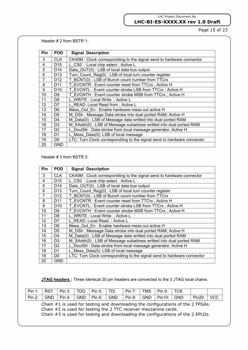
Header # 2 from BSTR 1: Pin POD Signal Description 3 CLK CK40M : Clock correspondiing to the signal send to hardware connector 4 D15 L_CS0 : Local chip select : Active L 5 D14 Data_OUT(0) : LSB of local data bus output 6 D13 Turn_Count_Reg(0) : LSB of local turn counter register 7 D12 T_BCNT(0) : LSB of Bunch count number from TTCrx 8 D11 T_EVCNTR : Event counter reset from TTCrx ; Active H 9 D10 T_EVCNTL : Event counter strobe LSB from TTCrx ; Active H 10 D9 T_EVCNTH : Event counter strobe MSB from TTCrx ; Active H 11 D8 L_WRITE : Local Write ; Active L 12 D7 L_READ: Local Read from ; Active L 13 D6 Mess_Out_En : Enable hardware mess out active H 14 D5 M_DStr : Message Data strobe into dual ported RAM; Active H 15 D4 M_Data(0) : LSB of Message data writted into dual ported RAM 16 D3 M_SAddr(0) : LSB of Message subadress writted into dual ported RAM 17 D2 L_DoutStr : Data strobe from local message generator; Active H 18 D1 L_Mess_Data(0): LSB of local message 19 D0 LTC: Turn Clock correspondiing to the signal send to hardware connector 20 GND Header # 3 from BSTR 2: Pin POD Signal Description 3 CLK CK40M : Clock correspondiing to the signal send to hardware connector 4 D15 L_CS0 : Local chip select : Active L 5 D14 Data_OUT(0) : LSB of local data bus output 6 D13 Turn_Count_Reg(0) : LSB of local turn counter register 7 D12 T_BCNT(0) : LSB of Bunch count number from TTCrx 8 D11 T_EVCNTR : Event counter reset from TTCrx ; Active H 9 D10 T_EVCNTL : Event counter strobe LSB from TTCrx ; Active H 10 D9 T_EVCNTH : Event counter strobe MSB from TTCrx ; Active H 11 D8 L_WRITE : Local Write ; Active L 12 D7 L_READ: Local Read ; Active L 13 D6 Mess_Out_En : Enable hardware mess out active H 14 D5 M_DStr : Message Data strobe into dual ported RAM; Active H 15 D4 M_Data(0) : LSB of Message data writted into dual ported RAM 16 D3 M_SAddr(0) : LSB of Message subadress writted into dual ported RAM 17 D2 L_DoutStr : Data strobe from local message generator; Active H 18 D1 L_Mess_Data(0): LSB of local message 19 D0 LTC: Turn Clock correspondiing to the signal send to hardware connector 20 GND JTAG headers : Three identical 20 pin headers are connected to the 3 JTAG local chains.
Chain #1 is used for testing and downloading the configurations of the 2 FPGAs. Chain #2 is used for testing the 2 TTC receiver mezzanine cards. Chain #3 is used for testing and downloading the configurations of the 2 EPLDs.
LHC Project Document No.
LHC-BI-ES-XXXX.XX rev 1.0 Draft
Page 16 of 23
7. BOARD CONFIGURATION
Strap settings: • On theTTCrm boards : TCrx configuration mode: PROM = Configuration downloaded from serial PROM on power-on or TTC reset. NO PROM = Default configuration or downloaded from I2C bus or TTC commands. NM0 and NM1 should be set to GND for normal operation • ST1:. Enable / Disable SCAN bridge (Used only for debugging)
ON = Enable SCAN bridge to access the 3 JTAG chains from VME [4] MTM bus. OFF = Disable SCAN bridge to perform a direct access to local JTAG port.
• ST2, ST3, ST4, ST5, ST6, ST7 : SCAN bridge address for MTM bus access. ON ON OFF OFF ON ON = 12 : corresponding to the VME slot 12 ( Default)
• ST8, ST9, ST10, ST11, ST12, ST13, ST14 : VME Interrupt pin connection : 1 .. 7. OFF ON OFF OFF OFF OFF OFF = Level 2 ( Default)
• ST15, ST16, ST17: BSTR1 FPGA configuration mode M1, M0, M2 (see XILINX specifications.) • ST18, ST19, ST20: BSTR2 FPGA configuration mode M1, M0, M2 (see XILINX specifications.) ON OFF OFF = Configuration downloaded from JTAG port chain 1. (For test only)
ON ON ON = Configuration downloaded from XC18V01 flash PROM. (Default) The configurations are first downloaded into the PROM using the JTAG port, then transferred to the FPGAs on next power-on, or by setting the reprogram bit of global control register.
• ST8 : 3.3V power supply source according to the VME64x specification [12]. P3V3 = from VME P1 connector: if provided by VME64x power crate. (Default) P3V3A = from on-board TPS767D325 regulator (to be plug in standard VME crate)
8. MEMORY MAP
All VME accesses are A16/D8 or A23/D32 bits, using block transfer capability.
The BOBR uses 3 blocks of address space defined as follow: • Block 0 = 256 bytes of VME I/O space (A16/D8) : Base Adress = B0 00 hex.
Mapped into an XC95144 EPLD. For global control registers, I2C and JTAG interfaces.
• Block 1 = 16 Kbytes of VME Memory space (A24/D32) : Base Adress = B0 00 00 hex. Mapped into an XC2S100 FPGA. For all BSTR 1 control registers and RAMs.
• Block 2 : 16 Kbytes of VME Memory space (A24/D32) : Base Adress = B1 00 00 hex.
Mapped into an XC2S100 FPGA.For all BSTR 2 control registers and RAMs.
On power ON, the VME interface EPLD and the 2 BSTR FPGAs are initialised with the predefined configuration. A vectorised VME interrupt request can be send using Local Interrupt from the 2 BSTR FPGAs . The level is predefined at 2, but can be easily modified by editing the VHDL code.
LHC Project Document No.
LHC-BI-ES-XXXX.XX rev 1.0 Draft
Page 17 of 23
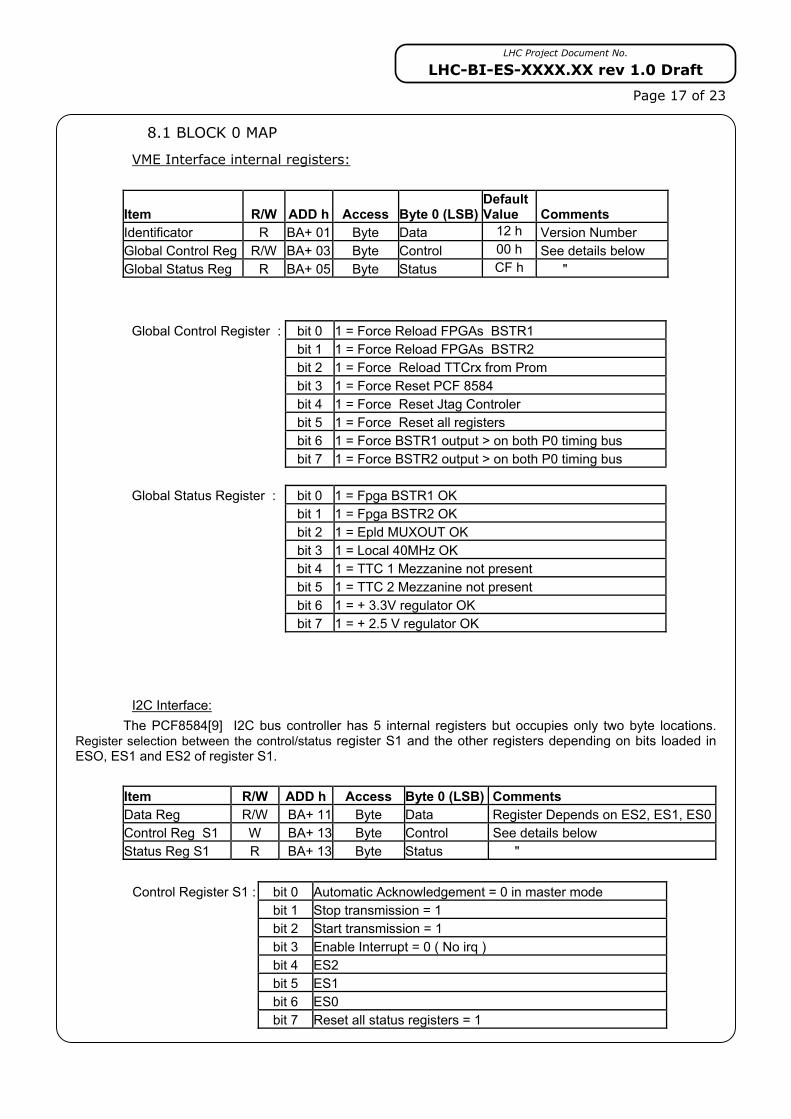
8.1 BLOCK 0 MAP
VME Interface internal registers:
Item R/W ADD h Access Byte 0 (LSB)Default Value Comments
Identificator R BA+ 01 Byte Data 12 h Version Number Global Control Reg R/W BA+ 03 Byte Control 00 h See details below Global Status Reg R BA+ 05 Byte Status CF h "
Global Control Register : bit 0 1 = Force Reload FPGAs BSTR1 bit 1 1 = Force Reload FPGAs BSTR2 bit 2 1 = Force Reload TTCrx from Prom bit 3 1 = Force Reset PCF 8584 bit 4 1 = Force Reset Jtag Controler bit 5 1 = Force Reset all registers bit 6 1 = Force BSTR1 output > on both P0 timing bus bit 7 1 = Force BSTR2 output > on both P0 timing bus Global Status Register : bit 0 1 = Fpga BSTR1 OK bit 1 1 = Fpga BSTR2 OK bit 2 1 = Epld MUXOUT OK bit 3 1 = Local 40MHz OK bit 4 1 = TTC 1 Mezzanine not present bit 5 1 = TTC 2 Mezzanine not present bit 6 1 = + 3.3V regulator OK
bit 7 1 = + 2.5 V regulator OK
I2C Interface:
The PCF8584[9] I2C bus controller has 5 internal registers but occupies only two byte locations. Register selection between the control/status register S1 and the other registers depending on bits loaded in ESO, ES1 and ES2 of register S1.
Item R/W ADD h Access Byte 0 (LSB) Comments Data Reg R/W BA+ 11 Byte Data Register Depends on ES2, ES1, ES0Control Reg S1 W BA+ 13 Byte Control See details below Status Reg S1 R BA+ 13 Byte Status " Control Register S1 : bit 0 Automatic Acknowledgement = 0 in master mode bit 1 Stop transmission = 1 bit 2 Start transmission = 1 bit 3 Enable Interrupt = 0 ( No irq ) bit 4 ES2 bit 5 ES1 bit 6 ES0 bit 7 Reset all status registers = 1
LHC Project Document No.
LHC-BI-ES-XXXX.XX rev 1.0 Draft
Page 18 of 23
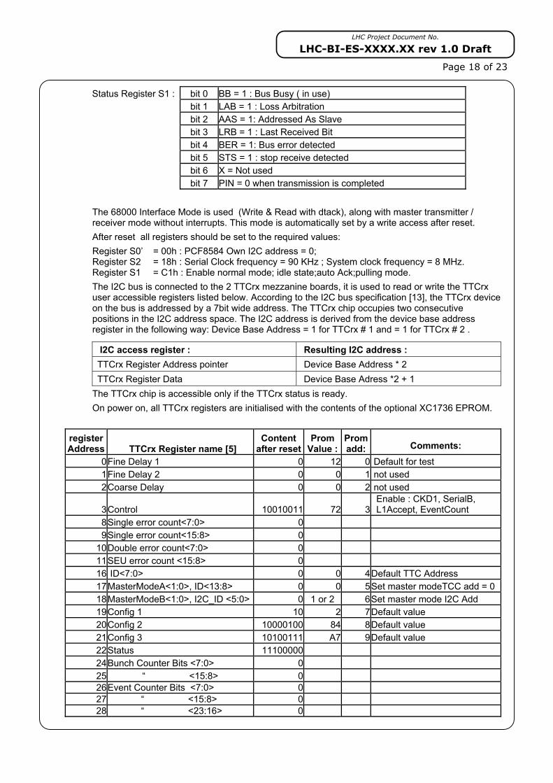
Status Register S1 : bit 0 BB = 1 : Bus Busy ( in use) bit 1 LAB = 1 : Loss Arbitration bit 2 AAS = 1: Addressed As Slave bit 3 LRB = 1 : Last Received Bit bit 4 BER = 1: Bus error detected bit 5 STS = 1 : stop receive detected bit 6 X = Not used
bit 7 PIN = 0 when transmission is completed
The 68000 Interface Mode is used (Write & Read with dtack), along with master transmitter / receiver mode without interrupts. This mode is automatically set by a write access after reset. After reset all registers should be set to the required values: Register S0’ = 00h : PCF8584 Own I2C address = 0; Register S2 = 18h : Serial Clock frequency = 90 KHz ; System clock frequency = 8 MHz. Register S1 = C1h : Enable normal mode; idle state;auto Ack;pulling mode. The I2C bus is connected to the 2 TTCrx mezzanine boards, it is used to read or write the TTCrx user accessible registers listed below. According to the I2C bus specification [13], the TTCrx device on the bus is addressed by a 7bit wide address. The TTCrx chip occupies two consecutive positions in the I2C address space. The I2C address is derived from the device base address register in the following way: Device Base Address = 1 for TTCrx # 1 and = 1 for TTCrx # 2 .
I2C access register : Resulting I2C address : TTCrx Register Address pointer Device Base Address * 2 TTCrx Register Data Device Base Adress *2 + 1
The TTCrx chip is accessible only if the TTCrx status is ready. On power on, all TTCrx registers are initialised with the contents of the optional XC1736 EPROM.
register Address TTCrx Register name [5]
Content after reset
Prom Value :
Promadd:
Comments:
0 Fine Delay 1 0 12 0 Default for test 1 Fine Delay 2 0 0 1 not used 2 Coarse Delay 0 0 2 not used
JTAG Interface : The SN74LVT8990A [12] controller manages the MTM Bus lines to be used for system testing by the crate controller to access each board connected to the VME64x backplane. The controller occupies 8 byte locations .
Item R/W ADD h Access On init Comments Config A R/W BA+ 21 Byte 00 h Configuration A register decode Config B R/W BA+ 23 Byte 80 h Configuration A register decode Status R BA+ 25 Byte 00 h Continuously updated Status Command R/W BA+ 27 Byte 00 h Control sate command register TDO buffer R/W BA+ 29 Byte 00 h Output FIFO register TDI buffer R BA+ 2b Byte 00 h Input FIFO register Counter R/W BA+ 2d Byte 00 h Test cycle counter Discret Control R/W BA+ 2f Byte 00 h Discret Control mode register
See Product Specifications for more details. The SCAN PSC110F [13] SCAN Bridge is connected to MTM Bus with Address = 0B , to acces the 3 JTAG local chains in order to allows in-situ board testing and FPGAs reprogramming.
8.2 BLOCK 1 MAP
BSTR 1:
Item R W Add h Access Byte 3 Byte 2 Byte 1 Byte 0 Comments Identificator R BA+ 00 LWord 01 12 Config Version VME IRQ vector W/R 08 LWord 00 Sent with IACK Control W 10 LWord Control See details below Control & Status R 10 LWord Status Control " Coarse Delay R/W 14 LWord bit 11 …. 0 25 ns step delay Hardware Bytes Select R/W 18 LWord Byte 1 Byte 0 0…255 ; 0…255 Hardware Bytes Output R 1C LWord Byte 1 Byte 0 read back outputs Bunch Sel. Out Enable R/W 20 LWord Bit 0..7 '1' = Enable output B. S. Enable Sub-Add R/W 24 LWord Sub Add Sub Add Enable Mask IRQ Bytes Addr Select R/W 30 LWord Byte 1 Byte 0 0…255 ; 0…255 IRQ Bytes Addr Mask R/W 34 LWord Byte 1 Byte 0 00…FF ; 00...FF Single TTC Error count R/W 40 LWord 16 bit counter Reset on write Double TTC Error count R/W 44 LWord 16 bit counter Reset on write Ready TTC Error count R/W 48 LWord 16 bit counter Reset on write Turn Clock Count R/W 50 LWord 24 bit counter Reset on write Local Message : R/W 80 LWord Sub Add Data Cmd 0 = 32 Commands R/W 84 LWord Sub Add Data Cmd 1 R/W 88 LWord Sub Add Data Cmd 2 .. …. …. …. … … R/W FC LWord Sub Add Data Cmd 31 MainDP Ram Mess Input R/W 800 LWord Cmd 0 CmdData @ SubAdd 0 = 256 Commands R/W 804 LWord Cmd 1 “ 1 … … … …. “ R/W BFC LWord Cmd 255 “ 255Aux DP Ram Message R/W C00 LWord Cmd 0 CmdData @ SubAdd 0= 256 Commands R/W C04 LWord Cmd1 “ 1 … … … … “ R/W FFC Cmd 255 “ 255
LHC Project Document No.
LHC-BI-ES-XXXX.XX rev 1.0 Draft
Page 20 of 23
Bunch Selection RAM R/W 1000 Lword Slot 3 Slot 2 Slot 1 Slot 0 3564 slots for LHC3564 slots X 8 outputs .. .. 924 slots for SPS
= 891 Lwords R/W 1DEC LwordSlot 3564
Slot 3563
Slot 3562 Slot 3561 Bit n = Output n
Control Register: bit 0 Internal mode = 1 ; External mode = 0 ( Default); bit 1 Sub mode : Single shot = 1; Repetitive = 0 ( Default) bit 2 DP Ram Write Control : Enable = 1; bit 3 Hardware Bytes Output Control : Enable = 1 bit 4 IRQ from Masks control : Enable = 1 bit 5 IRQ from Masks control : Clear Request = 1 bit 6 SPS = 1; LHC = 0 ( For diff. Bunch count ) bit 7 1 = request dump next message into Aux DPRAM Status Register: bit 0 TTC Input Ready = 1 ; 0 = No Input signal bit 1 1 = Local 40MHz present bit 2 1 = Local Turn Clock present bit 3 1 = TTC Serial B input signal present bit 4 1 = TTC Frame error bit 5 1 = Message record bit 6 1 = IRQ set from Masks bit 7 1= dump message into Aux DPRAM done
8.3 BLOCK 2 MAP
BSTR 2: Same as BSTR 1
9. CONTROL SOFTWARE
In order to use the BOBR board in the LHC BI Front Ends, a dedicated driver, the corresponding library as well as a local and remote test programs will be developed by the SL-BI software section.
The resulting interface will allow the user to:
– configure its BOBR (mainly select the bytes redirected to P0 and CPU interrupts).
– read asynchronously the generic information available like the beam intensity, energy, the GPS time or the internal error registers…
– subscribe to interruptions generated by the BOBR card.
This software will be made available for every operational platforms (CPU and Real Time OS) used by SL-BI. Today, this is limited to PowerPC CPUs running LynxOS3.1.
A first version of this software limited to the functionalities available in the SPS BST Master will be available around the 2002 start-up. It will be documented in a dedicated technical specification and available during Q2 2002 in the SL-BI software section EDMS repository for LHC software
[1] LHC Timing Requirements Gary BEETHAM SL/CO et al. http://lhc-proj-timwg.web.cern.ch/lhc-proj-timwg [2] Timing, Trigger and Control (TTC) Systems for LHC Detectors
Bruce TAYLOR EP/CMD http://ttc.web.cern.ch/TTC/intro.html
[3] LHC Machine Timing Distribution for the Experiments B.G. Taylor EP/CMD http://ttc.web.cern.ch/TTC/intro.html [4] VME64 Extensions "VME64x" (ANSI VITA 1.1997)
http://atlas.web.cern.ch/Atlas/GROUPS/FRONTEND/VMEbus/standards/Av1dot1.pdf [5] TTCrx Reference Manual: A Timing,Trigger and Control Receiver ASIC for LHC Detectors J.Christiansen EP/MIC et al. [6] Very high speed integrated circuit Hardware Description Language. IEEE 1164 standard. [7] THE LHC Machine TIMING SYSTEM FUNCTIONAL SPECIFICATION Gary BEETHAM SL/CO et al. [8] http://www.national.com/pf/SC/SCANPSC110F.html [9] PCF8584 I2C-bus controller; Product specification ; http://www.semiconductors.philips.com [10] The I2C BUS SPECIFICATION Version 2.0 December 1998 [11] JTAG / Boundary scan IEEE 1149.1 standard. [12] SN74LVT8980A EMBEDDED TEST-BUS CONTROLLERS http://www-s.ti.com/sc/psheets/scbs755a/scbs755a.pdf [13] SCANPSC110F SCAN Bridge Hierarchical and Multidrop Addressable
JTAG Port (IEEE1149.1 System Test Support) http://www.fairchildsemi.com/ds/SC/SCANPSC110F.pdf