29
LHC Splice Review, C. Scheuerlein, 18.10.2010 1 Local quality control of LHC electrical interconnections during the 2012 shutdown
| Date post: | 30-Dec-2015 |
| Category: |
Documents |
| Upload: | clementine-rosalyn-powers |
| View: | 216 times |
| Download: | 3 times |
LHC Splice Review, C. Scheuerlein, 18.10.2010
1
Local quality control of LHC electrical interconnections during the 2012 shutdown
Outline
o LHC splice quality control (QC) sequence during 2012 shutdown• QC of existing main interconnection splices• QC of disconnected main busbar cables before splice assembly• QC of newly connected main interconnection splices (without
shunts)• QC of shunt solder contacts; feasibility studies and development
of a new QC test• QC of entire splices with shunts• QC of line N connections• QC of line M connections• QC of splice insulation
o Other quality assurance (QA) activities
C. Scheuerlein, 18.10.2010 2
QC of existing (“old”) main interconnection splices
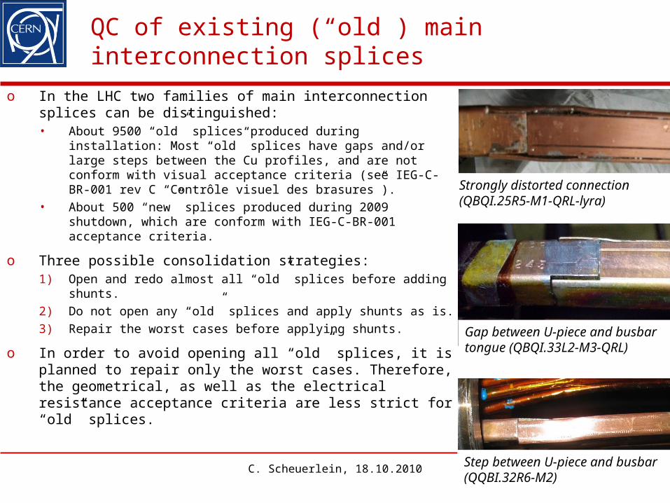
o In the LHC two families of main interconnection splices can be distinguished:• About 9500 “old” splices produced during installation:
Most “old” splices have gaps and/or large steps between the Cu profiles, and are not conform with visual acceptance criteria (see IEG-C-BR-001 rev C “Contrôle visuel des brasures”).
• About 500 “new” splices produced during 2009 shutdown, which are conform with IEG-C-BR-001 acceptance criteria.
o Three possible consolidation strategies:1) Open and redo almost all “old” splices before adding
shunts.2) Do not open any “old” splices and apply shunts as is.3) Repair the worst cases before applying shunts.
o In order to avoid opening all “old” splices, it is planned to repair only the worst cases. Therefore, the geometrical, as well as the electrical resistance acceptance criteria are less strict for “old” splices.
3C. Scheuerlein, 18.10.2010
Strongly distorted connection (QBQI.25R5-M1-QRL-lyra)
Step between U-piece and busbar (QQBI.32R6-M2)
Gap between U-piece and busbar tongue (QBQI.33L2-M3-QRL)
The R-8/R-16 test
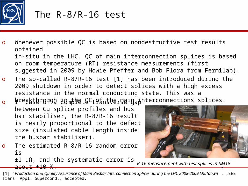
o Whenever possible QC is based on nondestructive test results obtained in-situ in the LHC. QC of main interconnection splices is based on room temperature (RT) resistance measurements (first suggested in 2009 by Howie Pfeffer and Bob Flora from Fermilab).
o The so-called R-8/R-16 test [1] has been introduced during the 2009 shutdown in order to detect splices with a high excess resistance in the normal conducting state. This was a breakthrough in the QC of the main interconnections splices.
C. Scheuerlein, 18.10.2010 4
R-16 measurement with test splices in SM18
o In case of a complete transverse gap between Cu splice profiles and bus bar stabiliser, the R-8/R-16 result is nearly proportional to the defect size (insulated cable length inside the busbar stabiliser).
o The estimated R-8/R-16 random error is ±1 µΩ, and the systematic error is about +10 %.
[1] “Production and Quality Assurance of Main Busbar Interconnection Splices during the LHC 2008-2009 Shutdown”, IEEE Trans. Appl. Supercond., accepted.
Distribution of additional R-8 values measured for “old” splices produced before 2009
C. Scheuerlein, 18.10.2010 5
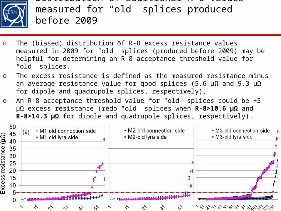
o The (biased) distribution of R-8 excess resistance values measured in 2009 for “old” splices (produced before 2009) may be helpful for determining an R-8 acceptance threshold value for “old” splices.
o The excess resistance is defined as the measured resistance minus an average resistance value for good splices (5.6 µΩ and 9.3 µΩ for dipole and quadrupole splices, respectively).
o An R-8 acceptance threshold value for “old” splices could be +5 µΩ excess resistance (redo “old” splices when R-8>10.6 µΩ and R-8>14.3 µΩ for dipole and quadrupole splices, respectively).
Alternative nondestructive tests: US transmission test
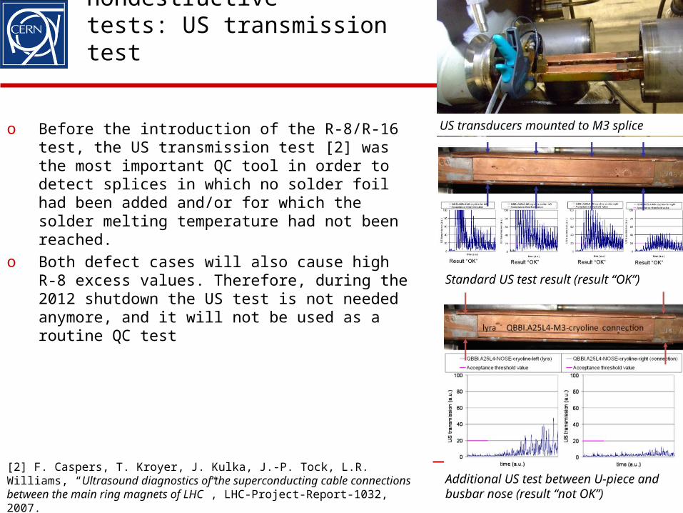
o Before the introduction of the R-8/R-16 test, the US transmission test [2] was the most important QC tool in order to detect splices in which no solder foil had been added and/or for which the solder melting temperature had not been reached.
o Both defect cases will also cause high R-8 excess values. Therefore, during the 2012 shutdown the US test is not needed anymore, and it will not be used as a routine QC test
C. Scheuerlein, 18.10.2010 6
US transducers mounted to M3 splice
[2] F. Caspers, T. Kroyer, J. Kulka, J.-P. Tock, L.R. Williams, “Ultrasound diagnostics of the superconducting cable connections between the main ring magnets of LHC”, LHC-Project-Report-1032, 2007.
Standard US test result (result “OK”)
Additional US test between U-piece and busbar nose (result “not OK”)
Alternative nondestructive tests: Gamma ray imaging
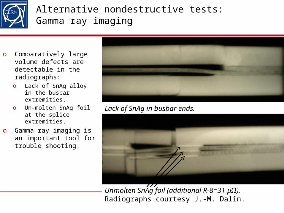
o Comparatively large volume defects are detectable in the radiographs:o Lack of SnAg alloy in
the busbar extremities.
o Un‑molten SnAg foil at the splice extremities.
o Gamma ray imaging is an important tool for trouble shooting.
7
Unmolten SnAg foil (additional R-8=31 µΩ). Radiographs courtesy J.-M. Dalin.
Lack of SnAg in busbar ends.
Gamma radiography as a QC tool?
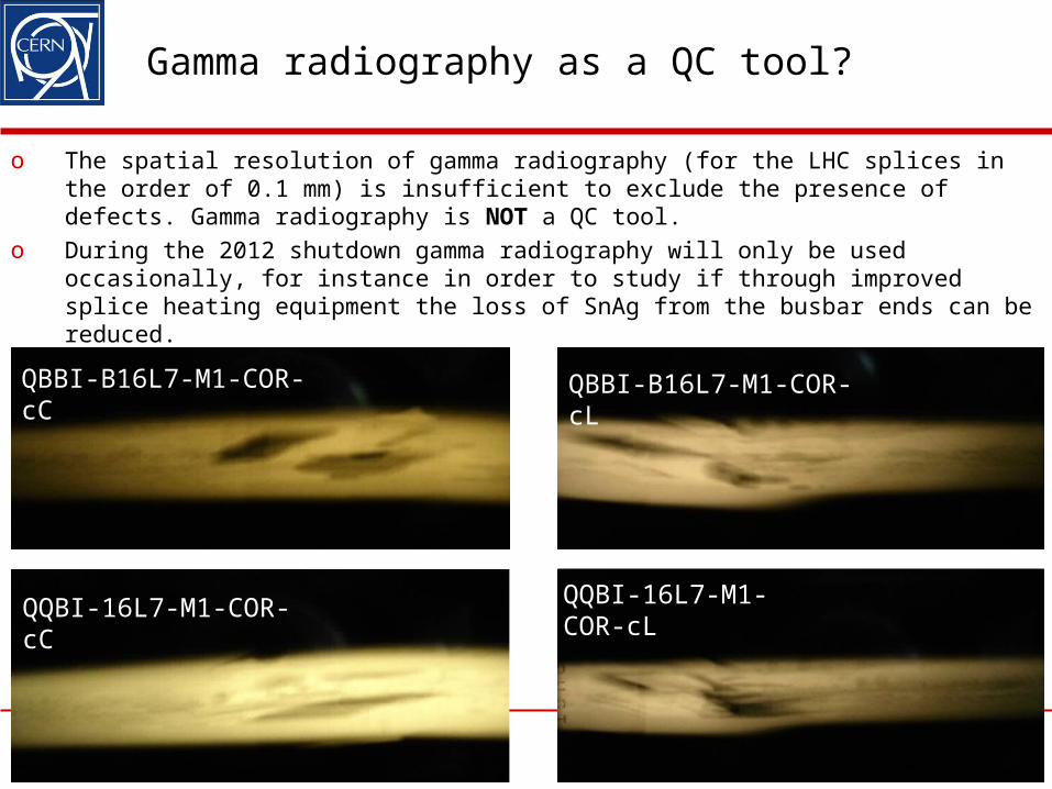
o The spatial resolution of gamma radiography (for the LHC splices in the order of 0.1 mm) is insufficient to exclude the presence of defects. Gamma radiography is NOT a QC tool.
o During the 2012 shutdown gamma radiography will only be used occasionally, for instance in order to study if through improved splice heating equipment the loss of SnAg from the busbar ends can be reduced.
8
QBBI-B16L7-M1-COR-cC QBBI-B16L7-M1-COR-cL
QQBI-16L7-M1-COR-cC QQBI-16L7-M1-COR-cL
QC of main busbar cables before splice assembly
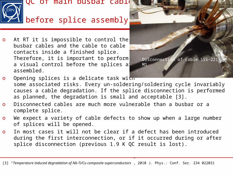
o At RT it is impossible to control the busbar cables and the cable to cable contacts inside a finished splice. Therefore, it is important to perform a a visual control before the splices are assembled.
o Opening splices is a delicate task with some associated risks. Every un-soldering/soldering cycle invariably causes a cable degradation. If the splice disconnection is performed as planned, the degradation is small and acceptable [3].
o Disconnected cables are much more vulnerable than a busbar or a complete splice.
o We expect a variety of cable defects to show up when a large number of splices will be opened.
o In most cases it will not be clear if a defect has been introduced during the first interconnection, or if it occurred during or after splice disconnection (previous 1.9 K QC result is lost).
C. Scheuerlein, 18.10.2010 9[3] “Temperature induced degradation of Nb-Ti/Cu composite superconductors”, 2010 J. Phys.: Conf. Ser. 234 022031
Disconnection of cable SSS-221-up-M1
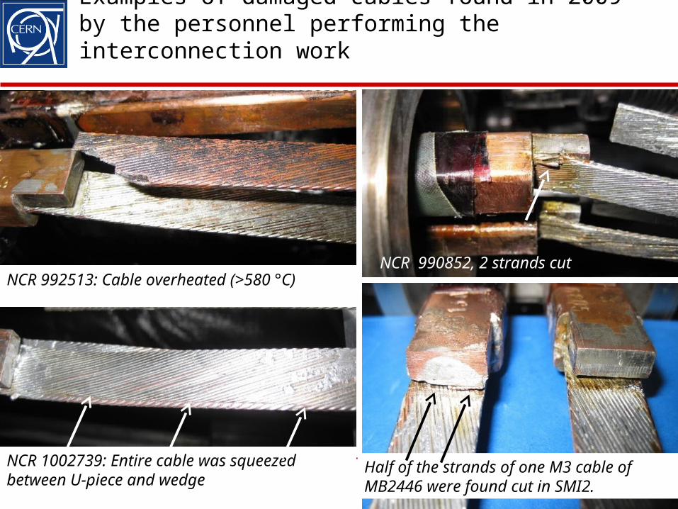
Examples of damaged cables found in 2009 by the personnel performing the interconnection work
10
NCR 1002739: Entire cable squeezed between U-piece and wedge
NCR 990852, 2 strands cutNCR 992513: Cable overheated (>580 °C)
Half of the strands of one M3 cable of MB2446 were found cut in SMI2.
NCR 1002739: Entire cable was squeezed between U-piece and wedge
QC of newly produced main interconnection splices (before application of shunts)
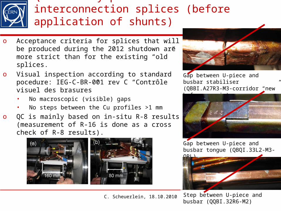
o Acceptance criteria for splices that will be produced during the 2012 shutdown are more strict than for the existing “old” splices.
o Visual inspection according to standard pocedure: IEG-C-BR-001 rev C “Contrôle visuel des brasures”• No macroscopic (visible) gaps• No steps between the Cu profiles >1 mm
o QC is mainly based on in-situ R-8 results (measurement of R-16 is done as a cross check of R-8 results).
C. Scheuerlein, 18.10.2010 11
QBBI.A27R3-M3-corridorGap between U-piece and busbar stabiliser (QBBI.A27R3-M3-corridor “new” before repair)
Gap between U-piece and busbar tongue (QBQI.33L2-M3-QRL)
Step between U-piece and busbar (QQBI.32R6-M2)
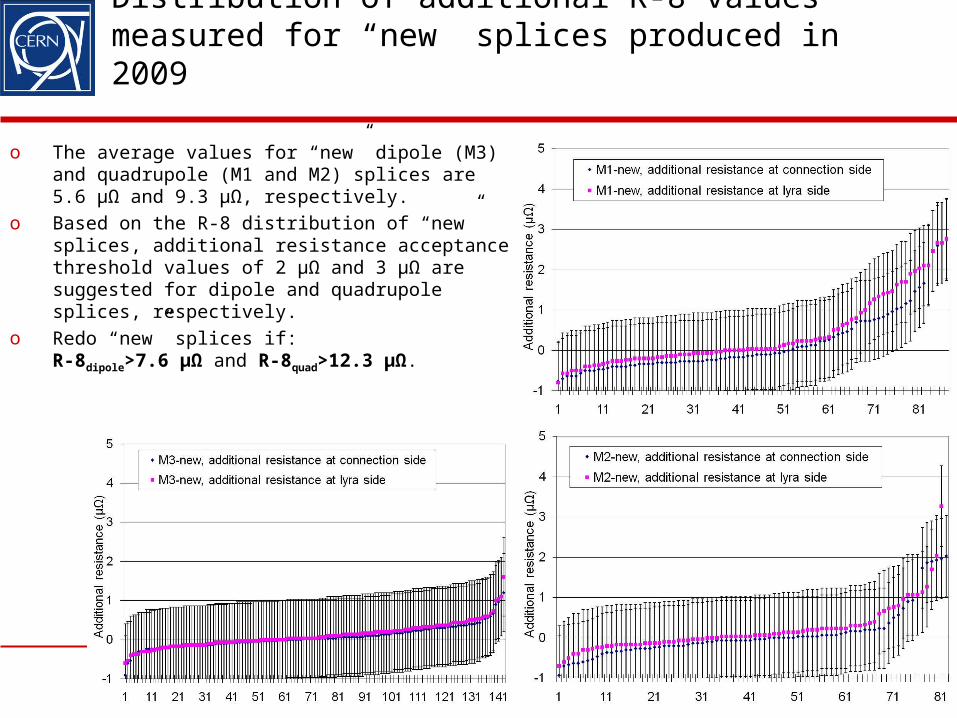
Distribution of additional R-8 values measured for “new” splices produced in 2009
C. Scheuerlein, 18.10.2010 12
o The average values for “new” dipole (M3) and quadrupole (M1 and M2) splices are 5.6 µΩ and 9.3 µΩ, respectively.
o Based on the R-8 distribution of “new” splices, additional resistance acceptance threshold values of 2 µΩ and 3 µΩ are suggested for dipole and quadrupole splices, respectively.
o Redo “new” splices if: R-8dipole>7.6 µΩ and R-8quad>12.3 µΩ.
QC of shunt solder contacts
o At least 40 000 shunt solder connections have to be produced and tested for the consolidation of the LHC main interconnection splices.
o The shunts should work as a fully redundant system. Therefore, it is necessary to control each solder contact separately (it is not sufficient to control only the complete splice with shunts).
o An efficient nondestructive test is needed for this purpose (test duration per shunt solder contact <1 minute).
o Three nondestructive testing methods have been studied:• Ultrasonic testing (at CERN [4], EMPA [5] and BAM [6]).• Active thermography (at BAM [7]).• Electrical resistance (at CERN [8]).
13
[4] J.-M. Dalin, CERN EN-MME, in collaboration with Olympus, GE and ECCND.[5] J. Neuenschwander, “Feasibility study NDT of solder joints”, Swiss Federal Laboratories for Materials Testing and Research (EMPA), Dübendorf, Test Report No 455081-10, (2010) [6] G. Brekow, D. Brackrock, “Ultrasonic testing of solder joints using a phased array technique with matrix arrays”, Federal Institute for Materials Research and Testing (BAM), Berlin, report reference number: 4326166 part 1, 99117 LHC-CONS, (2010).[7] C. Maierhofer, M Röllig, “Feasibility study for non-destructive testing of solder joints – Results of active thermography”, BAM, report reference number: 4326166 part 2, 99117 LHC-CONS, (2010).[8] S. Heck et al., “Room temperature resistance measurements for the quality control of shunt solder connections for the consolidation of the LHC main interconnection splices”, CERN TE-Note-2010-34, EDMS Nr: 1097684, (2010)
Ultrasonic testing main conclusions
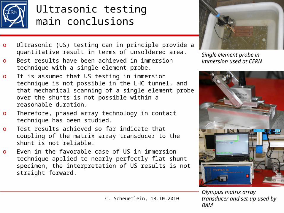
o Ultrasonic (US) testing can in principle provide a quantitative result in terms of unsoldered area.
o Best results have been achieved in immersion technique with a single element probe.
o It is assumed that US testing in immersion technique is not possible in the LHC tunnel, and that mechanical scanning of a single element probe over the shunts is not possible within a reasonable duration.
o Therefore, phased array technology in contact technique has been studied.
o Test results achieved so far indicate that coupling of the matrix array transducer to the shunt is not reliable.
o Even in the favorable case of US in immersion technique applied to nearly perfectly flat shunt specimen, the interpretation of US results is not straight forward.
C. Scheuerlein, 18.10.2010 14Olympus matrix array transducer and set-up used by BAM
Single element probe in immersion used at CERN
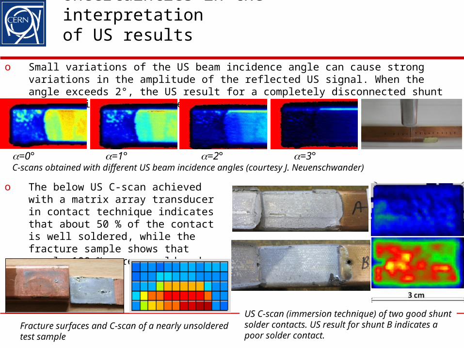
Uncertainties in the interpretation of US results
o Small variations of the US beam incidence angle can cause strong variations in the amplitude of the reflected US signal. When the angle exceeds 2°, the US result for a completely disconnected shunt appears like a good solder contact.
15
=0° =1° =2° =3°C-scans obtained with different US beam incidence angles (courtesy J. Neuenschwander)
o The below US C-scan achieved with a matrix array transducer in contact technique indicates that about 50 % of the contact is well soldered, while the fracture sample shows that nearly 100 % were unsoldered.
Fracture surfaces and C-scan of a nearly unsoldered test sample
US C-scan (immersion technique) of two good shunt solder contacts. US result for shunt B indicates a poor solder contact.
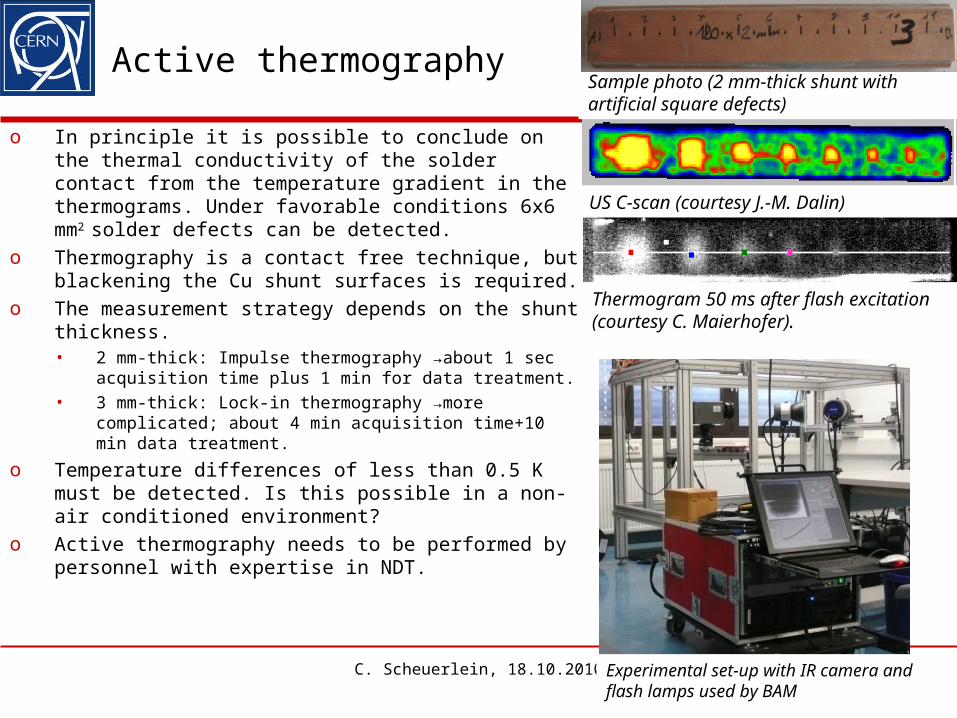
Active thermography
o In principle it is possible to conclude on the thermal conductivity of the solder contact from the temperature gradient in the thermograms. Under favorable conditions 6x6 mm2 solder defects can be detected.
o Thermography is a contact free technique, but blackening the Cu shunt surfaces is required.
o The measurement strategy depends on the shunt thickness. • 2 mm-thick: Impulse thermography →about 1 sec
acquisition time plus 1 min for data treatment.• 3 mm-thick: Lock-in thermography →more
complicated; about 4 min acquisition time+10 min data treatment.
o Temperature differences of less than 0.5 K must be detected. Is this possible in a non-air conditioned environment?
o Active thermography needs to be performed by personnel with expertise in NDT.
C. Scheuerlein, 18.10.2010 16
Sample photo (2 mm-thick shunt with artificial square defects)
US C-scan (courtesy J.-M. Dalin)
Thermogram 50 ms after flash excitation (courtesy C. Maierhofer).
Experimental set-up with IR camera and flash lamps used by BAM
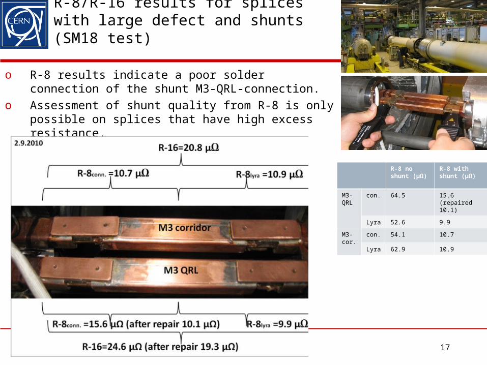
R-8/R-16 results for splices with large defect and shunts (SM18 test)
o R-8 results indicate a poor solder connection of the shunt M3-QRL-connection.
o Assessment of shunt quality from R-8 is only possible on splices that have high excess resistance.
C. Scheuerlein, 18.10.201017
R-8 no shunt (µΩ)
R-8 with shunt (µΩ)
M3-QRL
con. 64.5 15.6 (repaired 10.1)
Lyra 52.6 9.9
M3-cor.
con. 54.1 10.7
Lyra 62.9 10.9
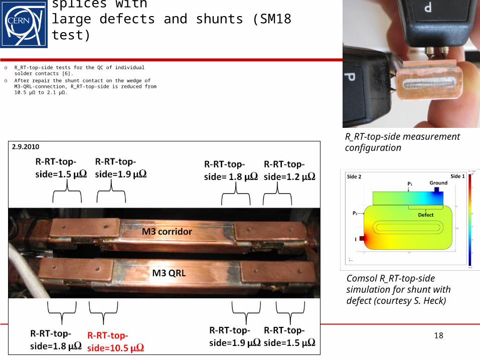
R_RT-top-side results for test splices with large defects and shunts (SM18 test)
o R_RT-top-side tests for the QC of individual solder contacts [6].
o After repair the shunt contact on the wedge of M3-QRL-connection, R_RT-top-side is reduced from 10.5 µΩ to 2.1 µΩ.
C. Scheuerlein, 18.10.2010 18
Comsol R_RT-top-side simulation for shunt with defect (courtesy S. Heck)
R_RT-top-side measurement configuration
Conclusion NDT of shunt solder contacts
o 100 % of the shunt solder contacts to be produced in the LHC tunnel will be controlled by a resistance test (in the so-called R_RT-top-side configuration).
o An acceptance threshold value needs to be determined when the final shunt layout is known. It could be about 2.5 µΩ (for comparison, R_RT-top-side of the defective shunt in SM18 was 10.5 µΩ).
o US studies at CERN, EMPA and BAM have shown that ultrasonic tests are a good tool to detect solder delaminations.
o Active thermography is another promising technique for testing shunt to solder contacts, in particular for 2 mm-thick shunts.
o It should be helpful to further develop and use ultrasonics and thermography methods as complementary analysis tools.
C. Scheuerlein, 18.10.2010 19
QC of complete splice with shunts
o After the R_RT-top-side test, a final R-8/R-16 test for all splices with shunts will be performed.
o R-8 acceptance threshold values need to be determined (could be about 10 µΩ and 6 µΩ for quadrupole and dipole splices, respectively, which is close to the values for perfect splices without shunts).
o The final R-8/R-16 test can be done directly after the R_RT-top-side tests of the shunt solder contacts.
C. Scheuerlein, 18.10.2010 20
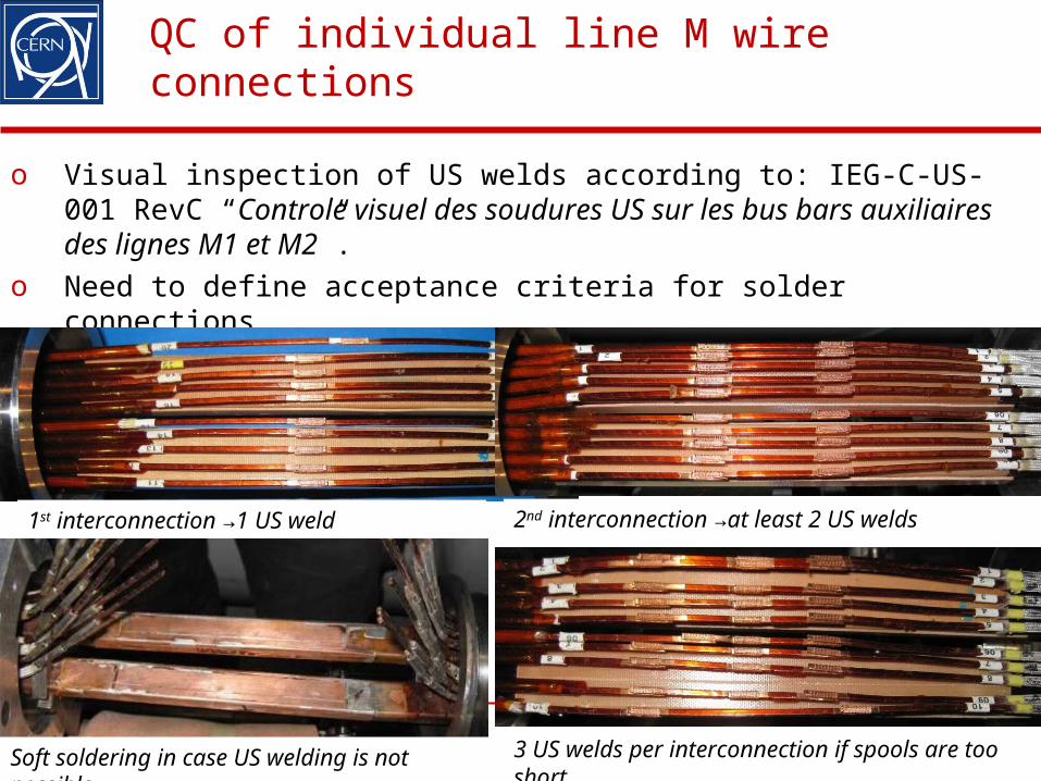
QC of individual line M wire connections
o Visual inspection of US welds according to: IEG-C-US-001 RevC “Controle visuel des soudures US sur les bus bars auxiliaires des lignes M1 et M2”.
o Need to define acceptance criteria for solder connections.
1st interconnection →1 US weld 2nd interconnection →at least 2 US welds
Soft soldering in case US welding is not possible 3 US welds per interconnection if spools are too short
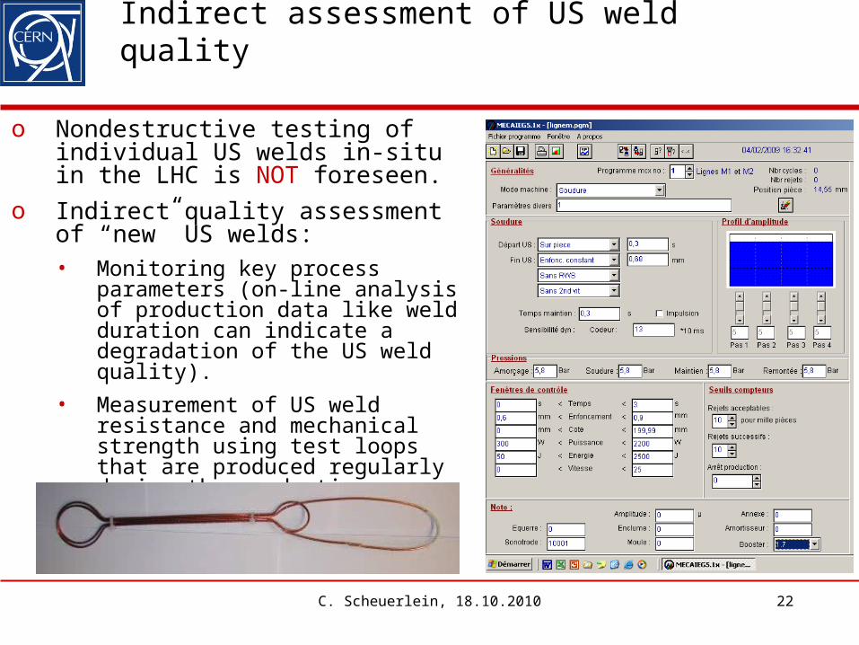
Indirect assessment of US weld quality
o Nondestructive testing of individual US welds in-situ in the LHC is NOT foreseen.
o Indirect quality assessment of “new” US welds:• Monitoring key process
parameters (on-line analysis of production data like weld duration can indicate a degradation of the US weld quality).
• Measurement of US weld resistance and mechanical strength using test loops that are produced regularly during the production.
C. Scheuerlein, 18.10.2010 22
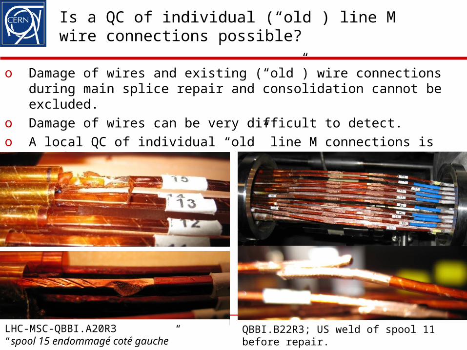
Is a QC of individual (“old”) line M wire connections possible?
o Damage of wires and existing (“old”) wire connections during main splice repair and consolidation cannot be excluded.
o Damage of wires can be very difficult to detect.o A local QC of individual “old” line M connections is NOT foreseen!
23LHC-MSC-QBBI.A20R3“spool 15 endommagé coté gauche”
QBBI.B22R3; US weld of spool 11 before repair.
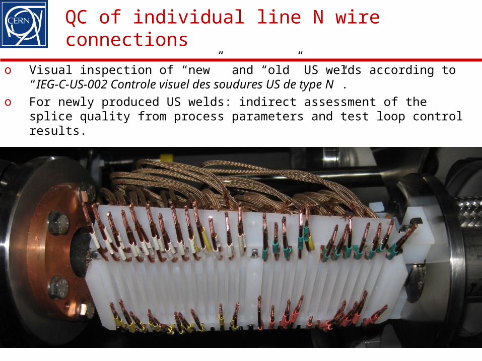
QC of individual line N wire connections
o Visual inspection of “new” and “old” US welds according to “IEG-C-US-002 Controle visuel des soudures US de type N”.
o For newly produced US welds: indirect assessment of the splice quality from process parameters and test loop control results.
C. Scheuerlein, 18.10.2010 24
Is a QC of individual (“old”) line N connections possible?.
25
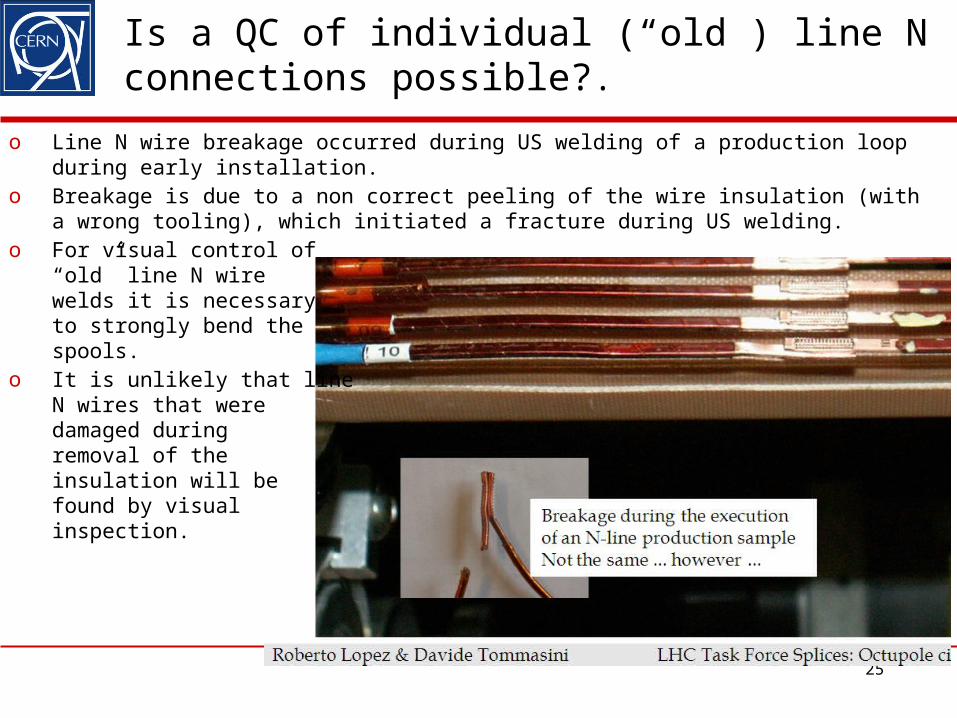
o Line N wire breakage occurred during US welding of a production loop during early installation.
o Breakage is due to a non correct peeling of the wire insulation (with a wrong tooling), which initiated a fracture during US welding.
o For visual control of “old” line N wire welds it is necessary to strongly bend the spools.
o It is unlikely that line N wires that were damaged during removal of the insulation will be found by visual inspection.
Local QC of spool insulation
C. Scheuerlein, 18.10.2010 26
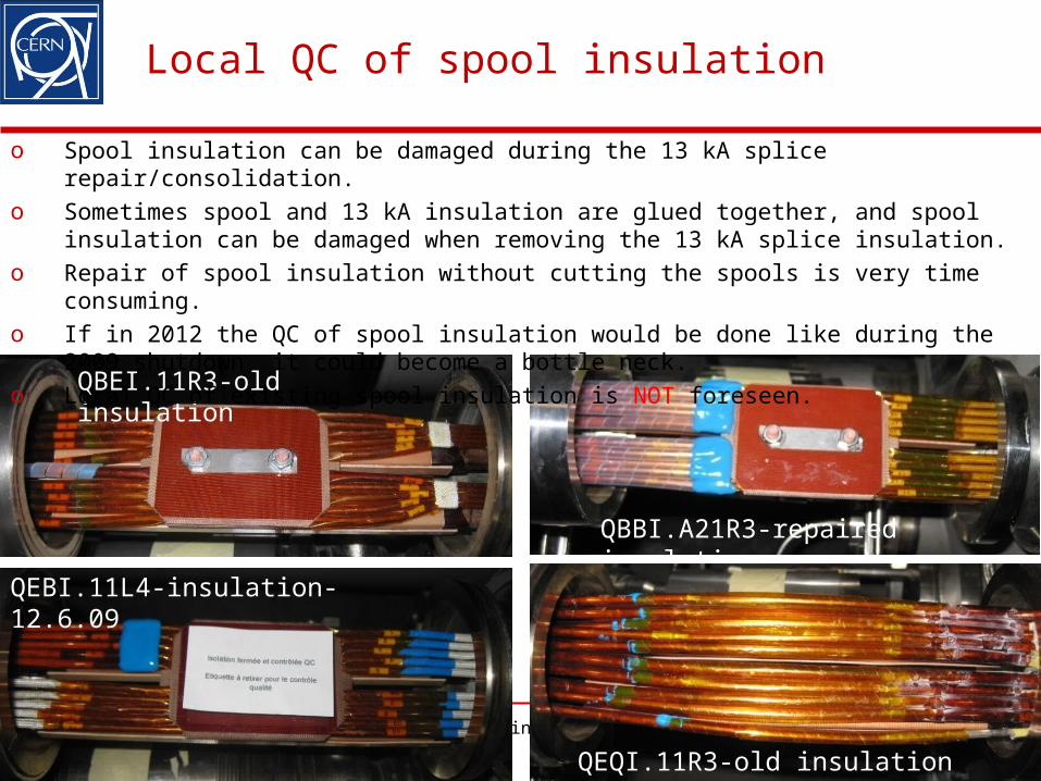
QBBI.A21R3-repaired insulation
QBEI.11R3-old
QEBI.11L4-insulation-12.6.09
QEQI.11R3-old insulation
QBEI.11R3-old insulation
o Spool insulation can be damaged during the 13 kA splice repair/consolidation. o Sometimes spool and 13 kA insulation are glued together, and spool insulation can
be damaged when removing the 13 kA splice insulation. o Repair of spool insulation without cutting the spools is very time consuming. o If in 2012 the QC of spool insulation would be done like during the 2009 shutdown,
it could become a bottle neck.o Local QC of existing spool insulation is NOT foreseen.
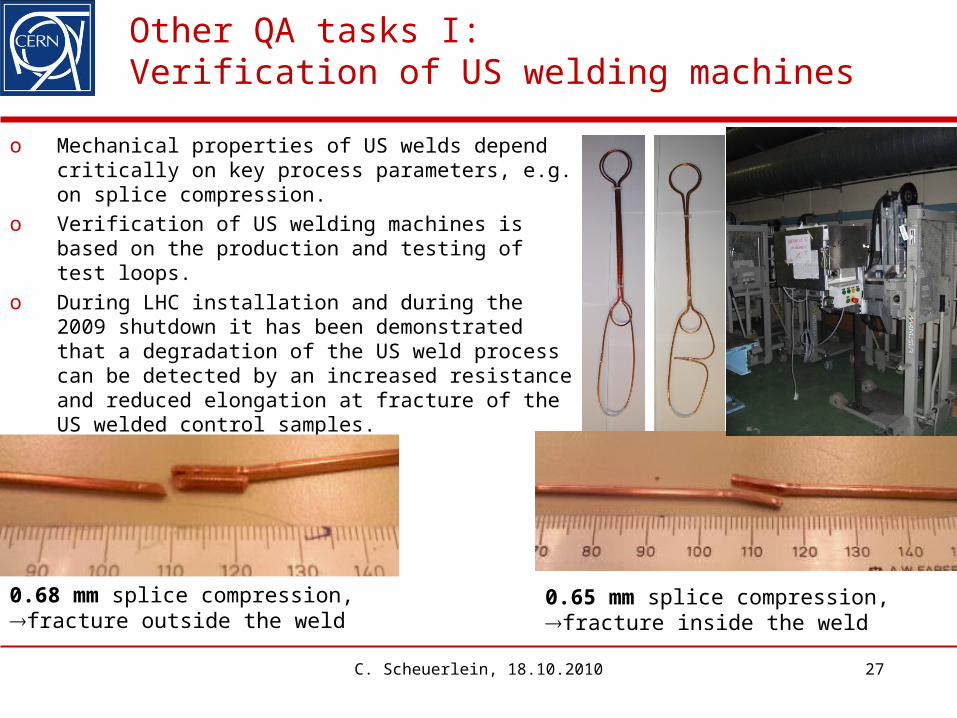
o Mechanical properties of US welds depend critically on key process parameters, e.g. on splice compression.
o Verification of US welding machines is based on the production and testing of test loops.
o During LHC installation and during the 2009 shutdown it has been demonstrated that a degradation of the US weld process can be detected by an increased resistance and reduced elongation at fracture of the US welded control samples.
C. Scheuerlein, 18.10.2010 27
0.65 mm splice compression,fracture inside the weld
Other QA tasks I: Verification of US welding machines
0.68 mm splice compression, fracture outside the weld
Other QA tasks II: Verification of main interconnection inductive soldering machines
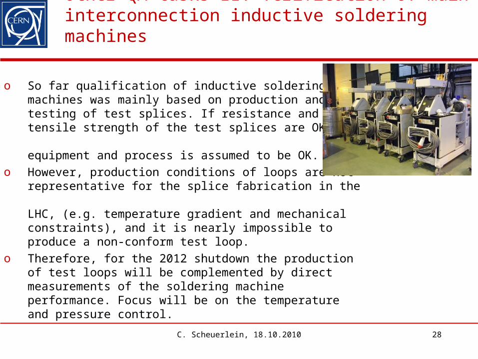
o So far qualification of inductive soldering machines was mainly based on production andtesting of test splices. If resistance and tensile strength of the test splices are OK, the equipment and process is assumed to be OK.
o However, production conditions of loops are not representative for the splice fabrication in the LHC, (e.g. temperature gradient and mechanical constraints), and it is nearly impossible to produce a non-conform test loop.
o Therefore, for the 2012 shutdown the production of test loops will be complemented by direct measurements of the soldering machine performance. Focus will be on the temperature and pressure control.
C. Scheuerlein, 18.10.2010 28
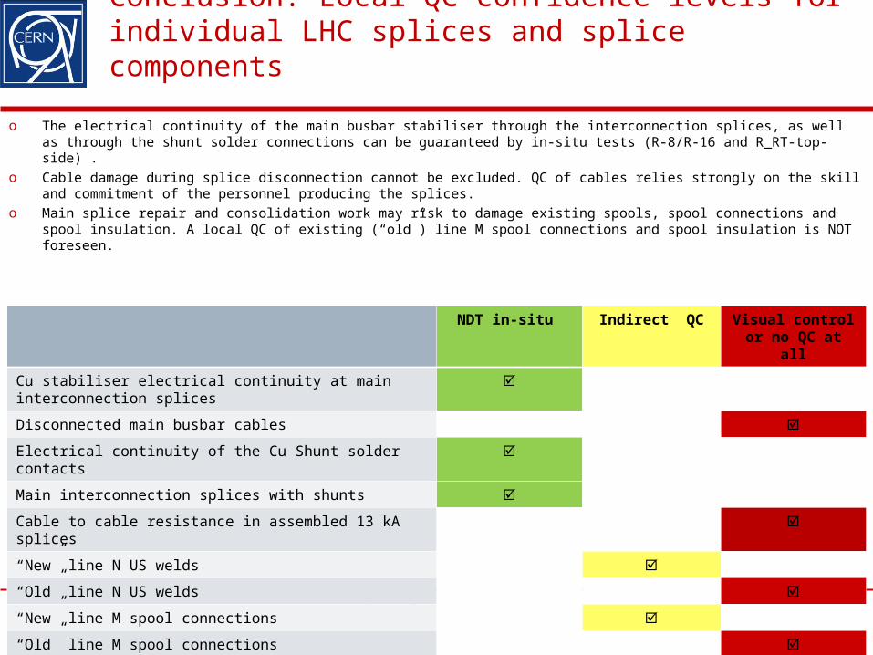
Conclusion: Local QC confidence levels for individual LHC splices and splice components
C. Scheuerlein, 18.10.2010 29
NDT in-situ Indirect QC Visual control or no QC at all
Cu stabiliser electrical continuity at main interconnection splices
Disconnected main busbar cables
Electrical continuity of the Cu Shunt solder contacts
Main interconnection splices with shunts
Cable to cable resistance in assembled 13 kA splices
“New” line N US welds
“Old” line N US welds
“New” line M spool connections
“Old” line M spool connections
Spool insulation
o The electrical continuity of the main busbar stabiliser through the interconnection splices, as well as through the shunt solder connections can be guaranteed by in-situ tests (R-8/R-16 and R_RT-top-side) .
o Cable damage during splice disconnection cannot be excluded. QC of cables relies strongly on the skill and commitment of the personnel producing the splices.
o Main splice repair and consolidation work may risk to damage existing spools, spool connections and spool insulation. A local QC of existing (“old”) line M spool connections and spool insulation is NOT foreseen.


